Aristo Craft Train Engineer Revolution
Eggliner Installation
revised 02-02-09
Installing the Aristo-Craft's new Revolution receiver in a plug-n-play socketed locomotive takes only a few minutes. Installing it in a locomotive that is not designed for plug-n-play is a bit more involved but not beyond the capabilities of most hobbyists. These notes will show you how to install the receiver in an Aristo-Craft Eggliner.
This installation is based on these assumptions:
the Eggliner will operate from track power - notes on battery operation are at the end.
the headlight and taillight will be operated by the receiver
the side lights will remain on at all times
a magnetically activated reed switch will be used to control the "link" switch
Opening the Eggliner
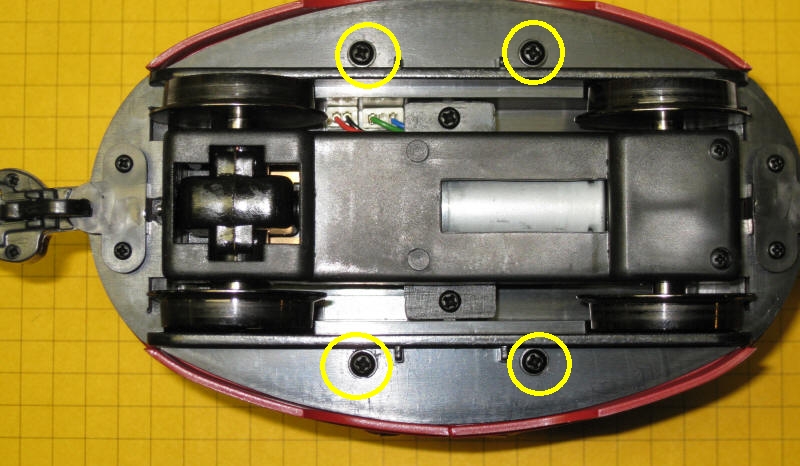
To remove the top of the Eggliner remove the four screws circled below.
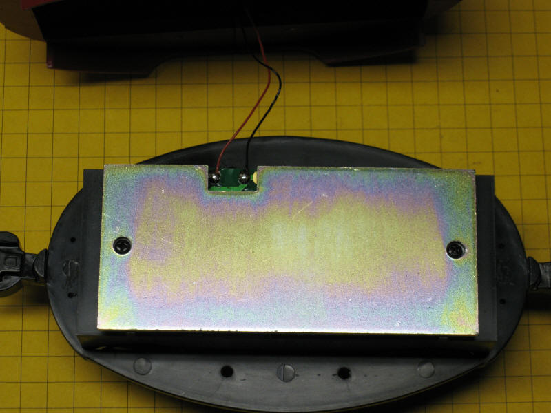
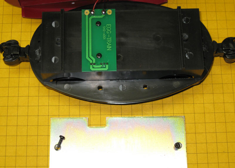
Separate the top and the bottom. There are two wires that connect the two sections. These supply power to the six lights in the Eggliner. The large metal plate on the base is a weight. Loosen the two screws on either end to remove it.
Modifying the circuit board
Once the weight is removed you can see the green circuit board.
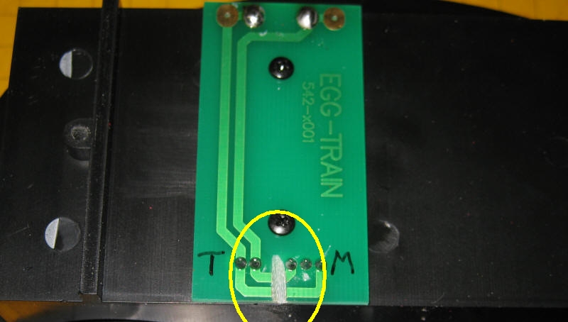
In this close-up of the circuit board the connections to the track (marked "T") and those to the motor (marked "M") are shown. We need to isolate these connections before we connect the Revolution adapter board.
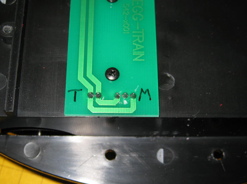
Use a utility knife or a Dremel to cut through both of the traces as shown here. Note that the two wires that go to the lights have been removed from the top two solder pads on the circuit board. Some changes will be made to the lighting wiring and wires will be reattached there later in the conversion.
Connecting to the Revolution receiver adapter board
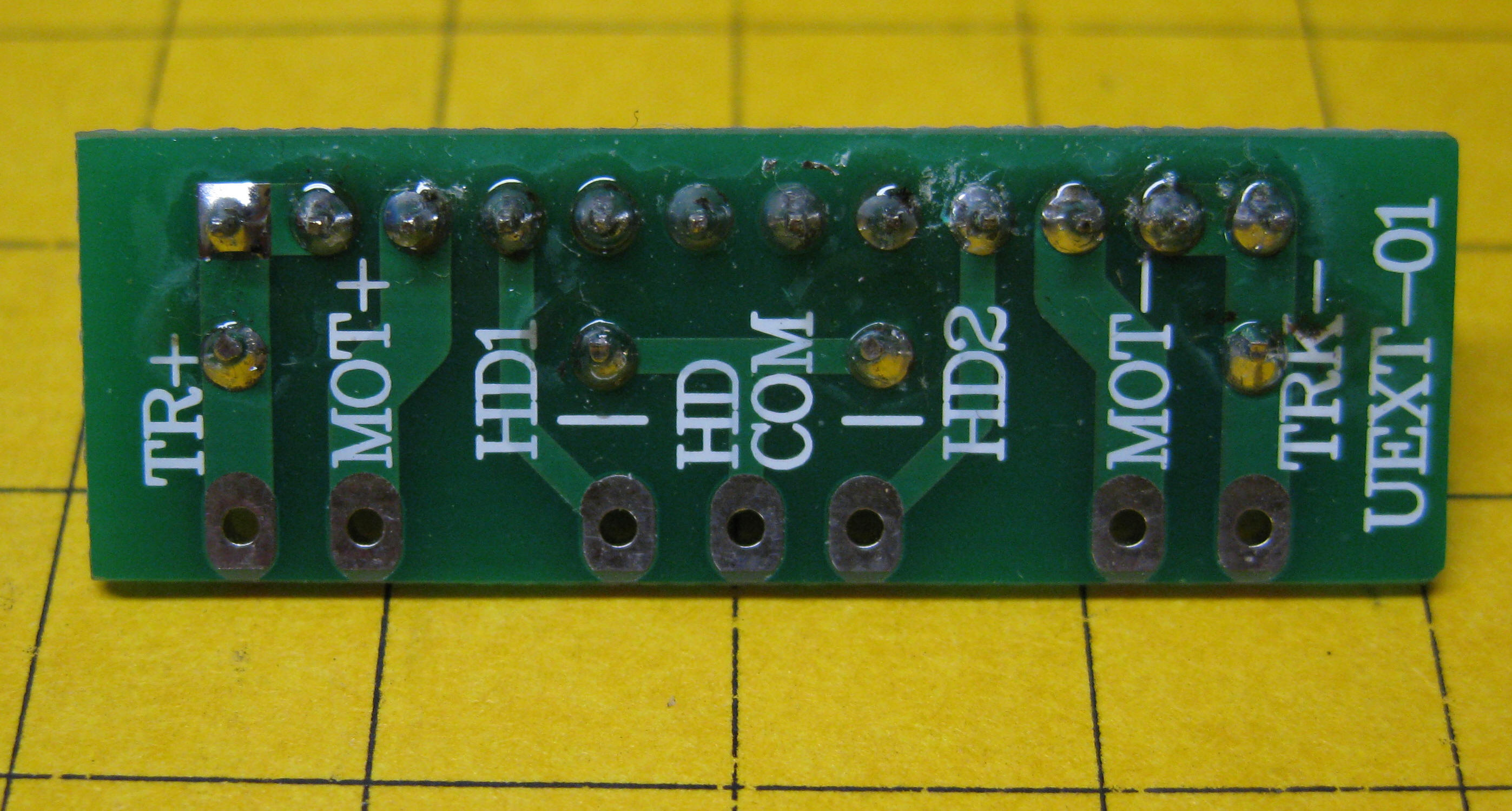
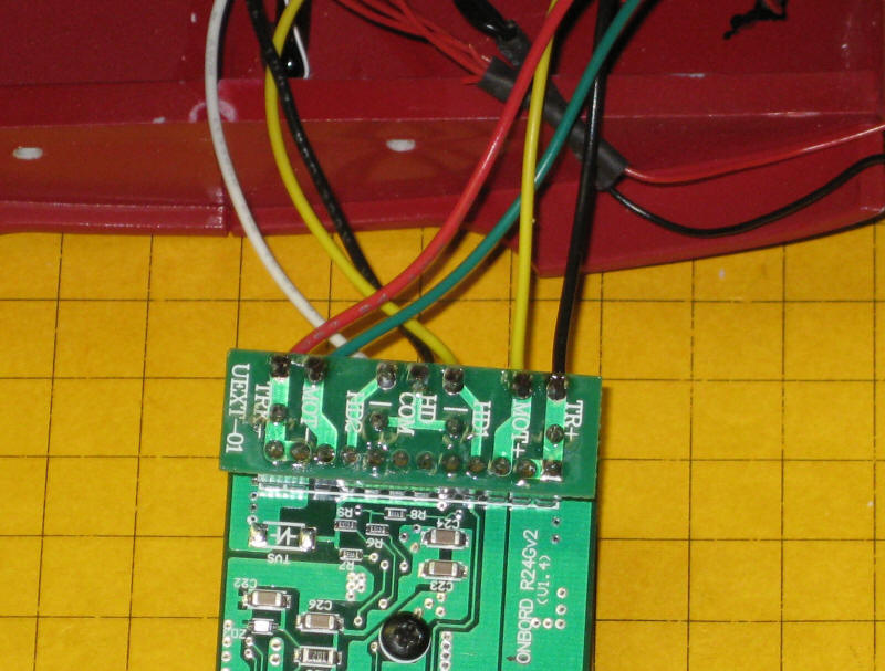
The labels on this view of the adapter board show that the track power goes to the two end connections (TR+ and TR-), the motor wires go to the next two connections (MOT+ and MOT-). The three center connections are for the head and tail lights.
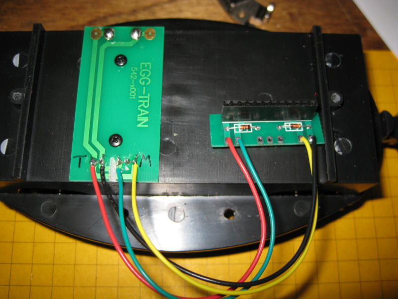
Four six inch long wires are used to connect the Eggliner circuit board to the Revolution receiver's adapter board. Note that the red and black wires connect the track connections and the green and yellow go to the motor contacts.
This view shows the bottom of the labeled side of the adapter board.
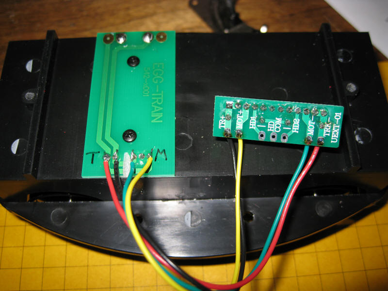
This completes the wiring for the motor and track power connections. If you don't care to change the lighting you can skip to the last section that shows how to mount the receiver. Just reconnect the red and black wires for the lighting to the two contacts at the top of the Eggliner circuit board and the lights will remain on at all times.
Lighting Modifications
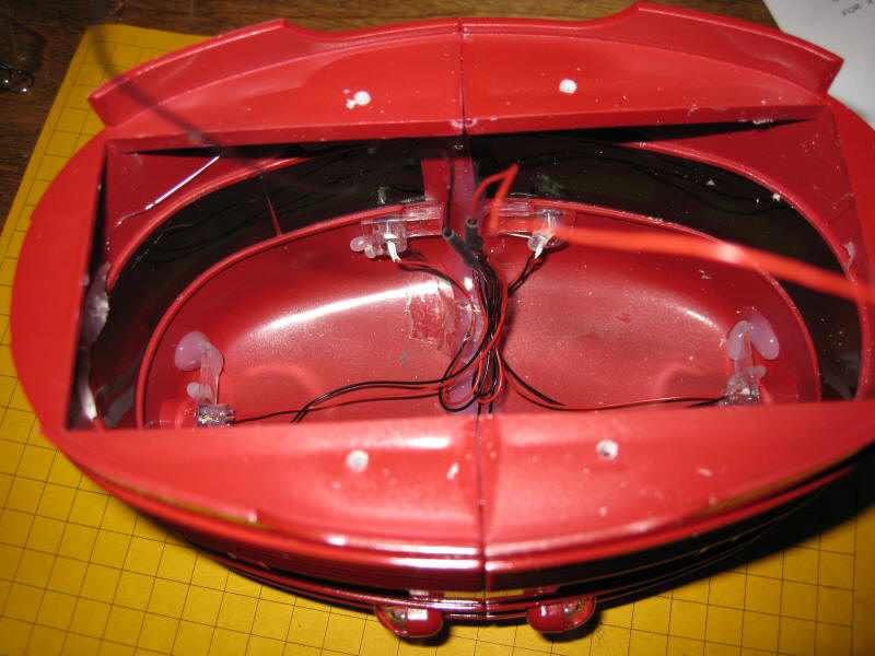
The Revolution receiver can operate front and rear lights so that the headlight comes on when the locomotive is going one way and the taillight comes on when it goes the other. The factory wiring has all six lights connected together in parallel. We need to isolate the wires for the front and rear lights while leaving the four side lights connected together.
A piece of white cardboard covers the bottom of the Eggliner body. It must be removed to gain access to the lights and to provide room for the Revolution receiver.
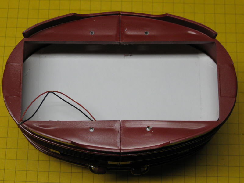
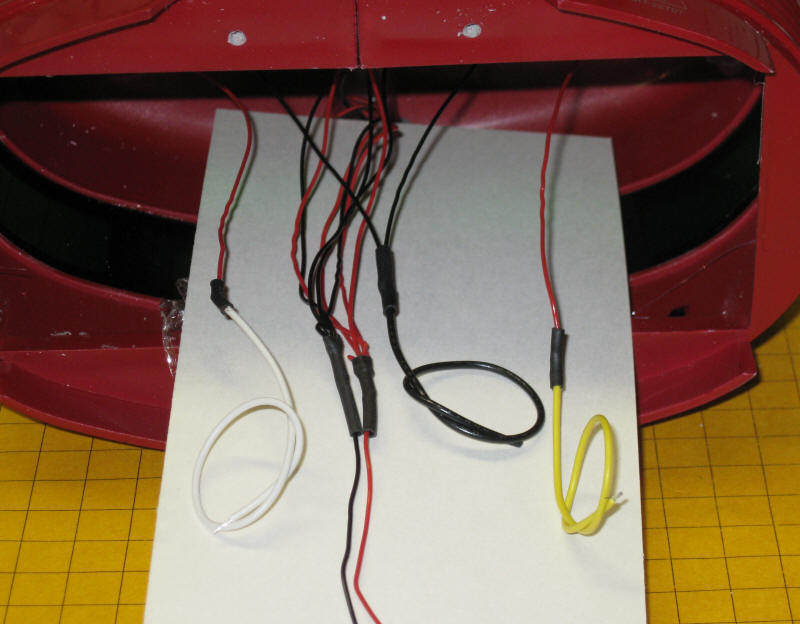
Here is the wiring as the unit is shipped. There is a red and a black wire from each of the six bulbs. They are joined together and connected to the single red and single black wire that were soldered to the circuit board.
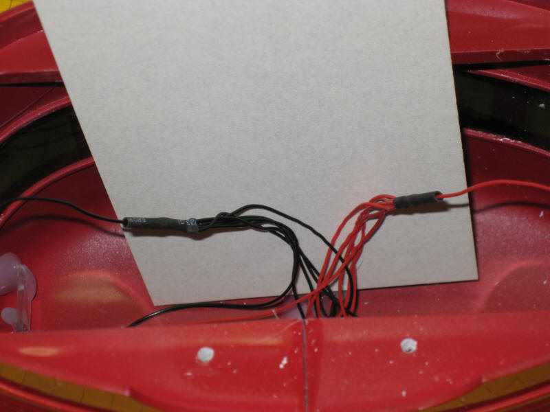
In this photo a white note card is behind the wires so that they can be seen more clearly.
Here are all of connections that need to be made. The four pairs of red and black wires in the center go to the four lights on the Eggliner's sides. They will connect directly to the track power so that they remain on at full brightness at all times.
The white wire connects to one of the taillight's wires and the yellow wire to one of the wires from the headlight. The other two wires from those bulbs are wired together and go to the thicker black wire.
Here the adapter board has been plugged into the 12 pin header on the receiver. You can see the white, black and yellow wires soldered to the three center lighting connections. They are labeled HD2 (taillight), HD COM (common) and HD1 (headlight).
Link Switch Installation
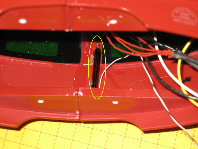
A linking switch is included with the Revolution receiver. This is a momentary SPST (Single Pole Single Throw) push button switch. It is normally installed by drilling a hold in the locomotive so that it can be reached from outside. I did not want to drill a hole in the Eggliner's body so I opted to replace it with a magnetic reed switch. That way I could place a small magnet on the outside of the Eggliner's body to activate linking.
I cut the push button switch off of the end of the linking cable and replaced it with a reed switch. The reed switch is glued to the inside of the Eggliner as shown here. The black and white wires plug into the linking socket on the receiver.
The completed wiring is shown here.
Final Installation
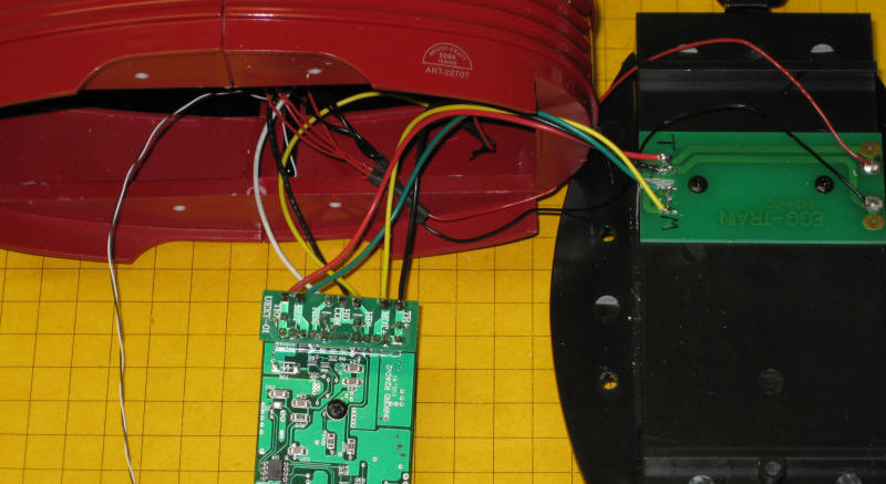
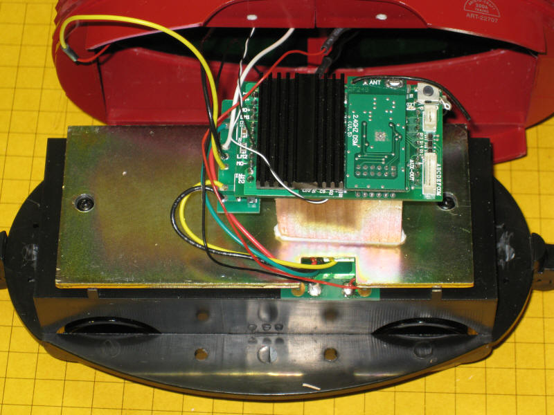
The wires between the adapter board and the Eggliner circuit need to be routed under the metal weight and through the notch in it so that the body can be put back on the base.
A 1.5" x 1.5" x 1" wood block is used to raise the receiver above the metal weight. It has been attached with double sided foam tape.
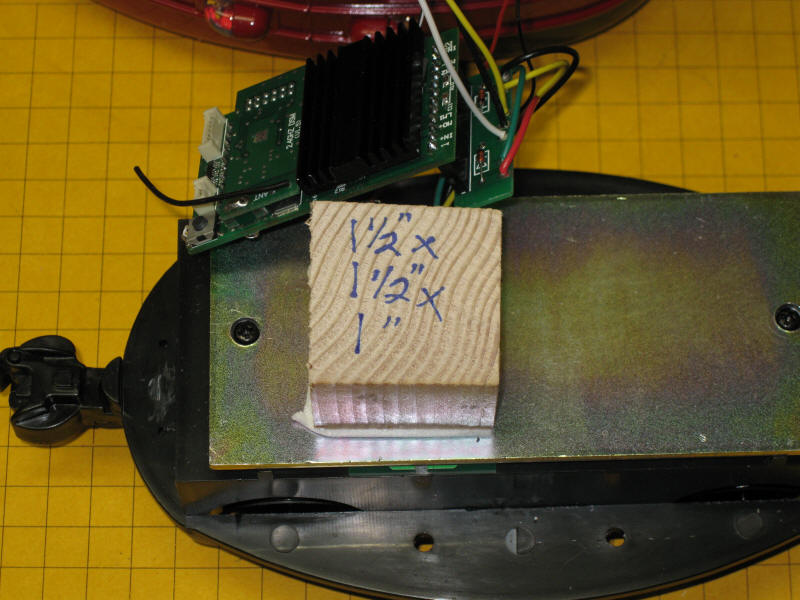
Here you can see the completed installation and the way that the red, black, yellow and green wires have been routed through the notch in the metal weight.
All that remains is to put the top back on and try it out on the rails!
Battery Operation
An Aristo-Craft lithium ion battery will fit inside of the Eggliner along with the Revolution receiver. If you want to operate on battery power change the procedures shown above as follows:
Note: as mentioned above the bulbs are incandescent and draw a good bit of power. For battery operation you may want to replace them with LEDs. This is a somewhat difficult modification as the existing bulbs and lamp fixtures don't come out very easily. It can be done but requires some care. You will also have to pay attention to polarity with LEDs. Make sure that the anodes (positive leads) from the headlight and taillight LEDs are wired together and go to the HD COM connection on the adapter board. The cathodes go to HD1 and HD2. Remember to put a 1K current limiting resistor in series with each LED.