Aristo Craft Revolution
Base Station
Using it to Drive Another Revolution
revised 07-14-11
Background:
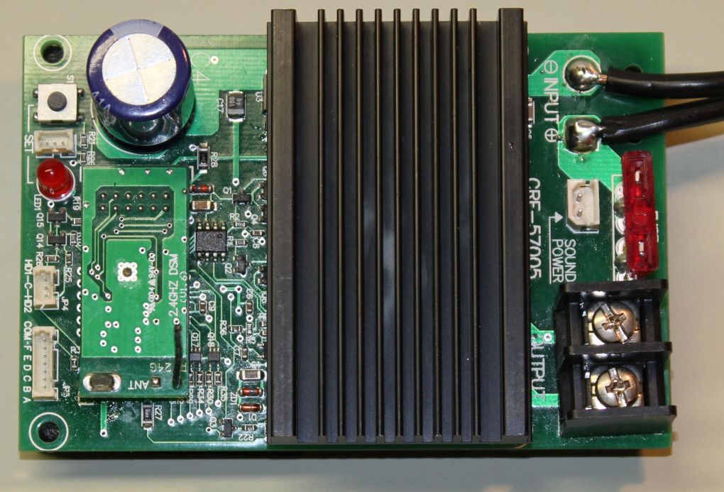
The Revolution Base Station (sometimes called the Track Side Revolution) is
designed to be used on-board trains that draw considerably more current than the
standard Revolution receiver can handle. It can be put inside of an ABA
consist and wired so that all three units run from it. It can also be
placed in a trailing battery car that powers one or more locomotives. In
track-side use it is connected directly to the track and used much the same as
the old revolution by powering a standard track powered locomotive that changes
speed as the track power changes.
The Question:
Can this unit be used to power track that a Revolution equipped train runs
on? The question arises due to the fact that the Revolution (all
varieties) sends out power using a method called PWM (also called PWC).
PWM sends out timed pulses of the full power that it is being fed in such a way
that a train's electric motor "sees" a varying voltage. For example, if
the PWM pulses of power are on for 1/1000 of a second then off for 1/1000 of a
second the motor acts as if it is getting 50% of the voltage. If the power
is on for 4/1000 and off for 1/1000 it performs as though it is getting 80%
power.
I believe that this question came up as some users would like to use the larger Revolution unit as a master control so that they could turn off all trains on a track by just turning the Base Station off. Although this could be accomplished in a number of less expensive ways I can understand the desire to have one transmitter that can control both the individual trains and the track power.
The Setup
I tested the question posed above by connecting the larger Revolution
receiver to a regulated 19 volt / 3 amp variable power supply that puts out pure
DC. I connected the output of the Revolution to my oscilloscope and was
pleased to see that the waveform was looked just like it does in the text books!
25% power setting - note that the line is above the center (zero volts) for about 1/4 of the time.
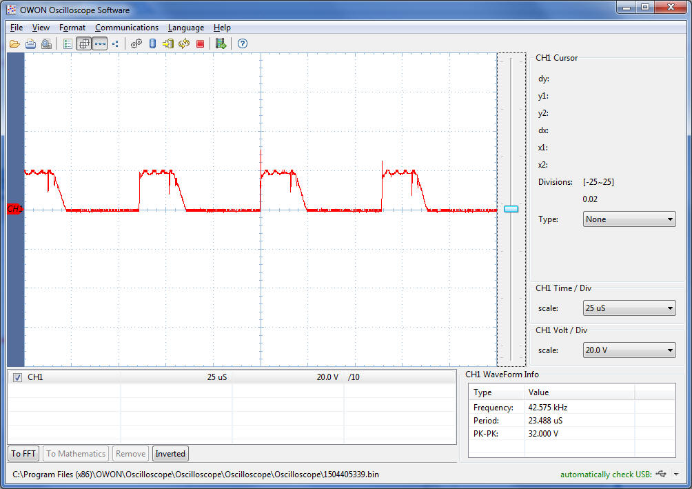
50% power setting - above about 1/2 of the time.

75% power setting - above about 3/4 of the time.

With the transmitter at 100% the scope shows a straight line. At this setting the power output is virtually the same as that of a linear power supply.
I successfully ran a locomotive that was wired directly to the output from the Base Station up and down in speed from 0 - 100 while I watched the scope. Since this is the way that the controller is designed to operate everything worked as expected.
I then put a Revolution equipped locomotive on rollers and hooked the track up to the output from the large Revolution that was also connected to the other locomotive. This setup simulates what would be used if you had the base unit track-side and one or more Revo equipped locos on the track pulling power from it. In reality you would not be likely to be using Locomotive 1 unless you had a non-revo equipped loco running on the track.
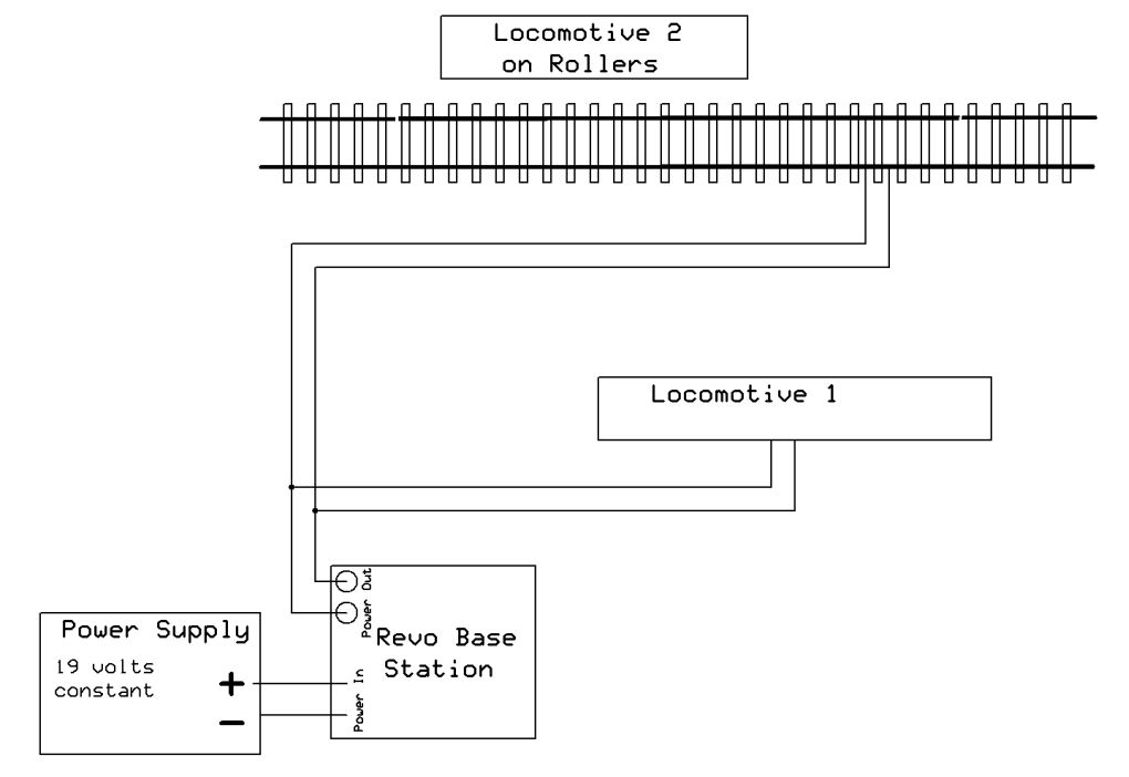
I was running Locomotive 1 at about 40% when I connected to the track under the other unit's rollers. Locomotive 1 immediately went to full speed. The second locomotive worked properly from the Revolution remote control but the first one was very unhappy. It did not begin to slow down until I got the speed down to about 15%. It was clear that something was getting back into the base station that was effecting its operation.
The next test involved the same setup but with a bridge rectifier between the output of the large Revolution and the train on the rollers. This simulates having the Revo's bridge rectifier board installed in the locomotive that is on the track. Again Locomotive 1 does not need to be there but it allowed me to test what was happening with the Base Station.
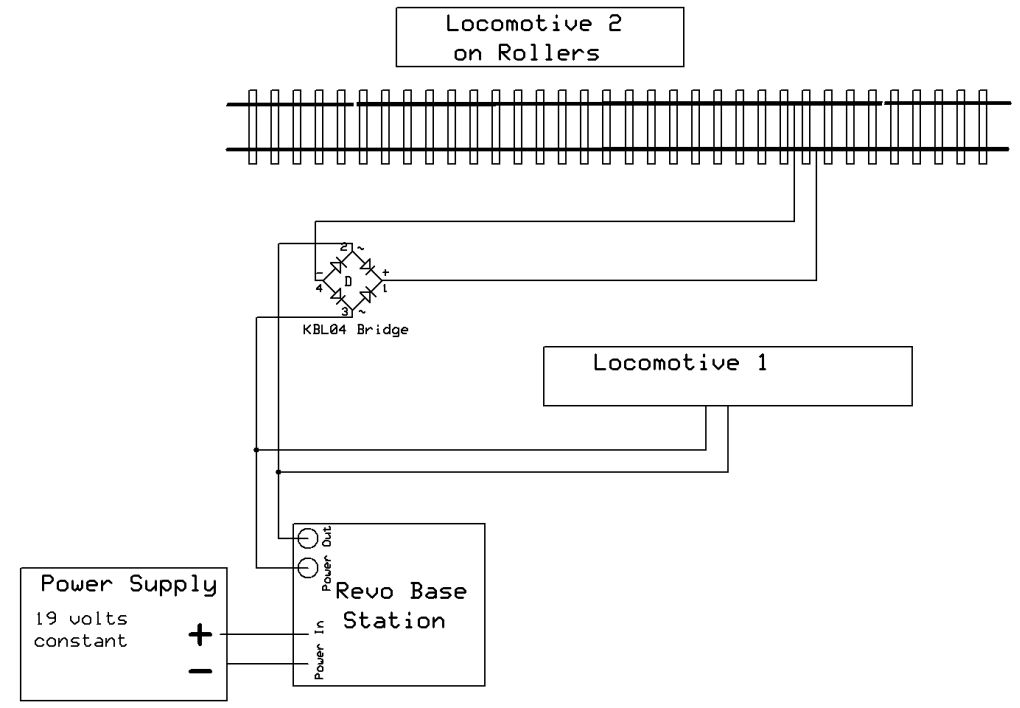
I was pleasantly surprised to find that both locomotives worked properly with the Revo transmitter. The base station supplied consistent power to both the directly connected loco and to the track powered loco. There was no effect from one to the other. When power dropped from the base station both locomotives slowed down but I could still change the speed of the second locomotive with the remote.
The next test was to disconnect Locomotive 1 and to add a second Revo equipped locomotive to the rollers - it also had a bridge rectifier. Both locos worked properly with the power from the Base Unit. When the Base Unit was powered down both locomotives stopped immediately.
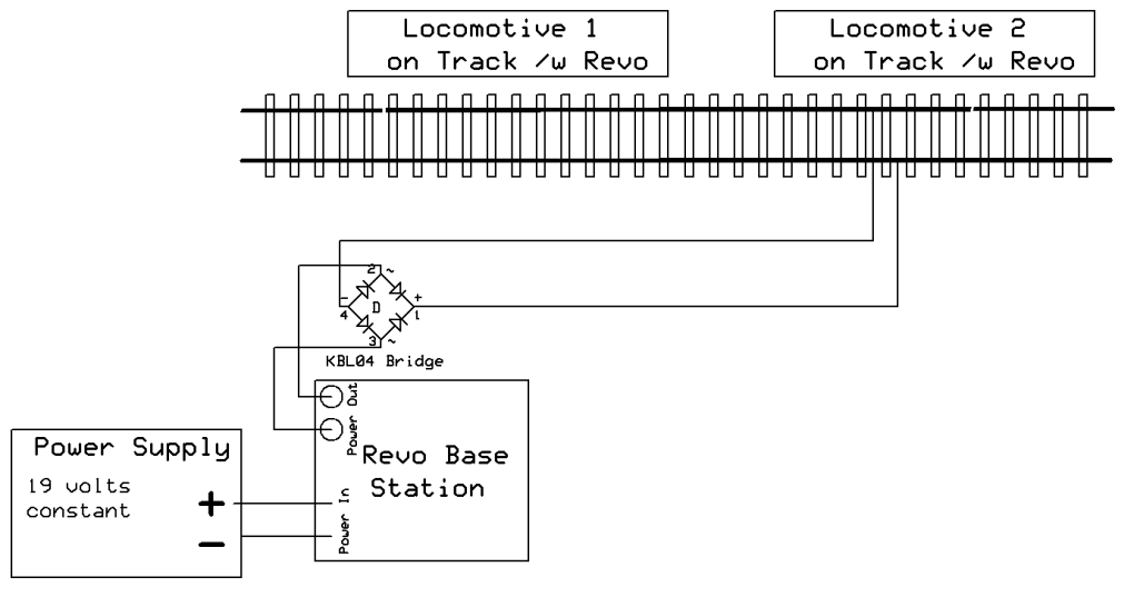
The final test was to put two trains on a loop of track, each with a non-bridge rectifier socket for the Revolution receiver, and a single bridge rectifier wired in between the Base Station and the track power wires as shown here. It worked very well and both locomotives and the Base Station responded properly to the transmitter.
Conclusion
This is not meant to be a complete examination of what should and should not
be done with the Revolution Base Station. It is just an experiment that I
set up to see what would happen if one Revolution's output (PWM) fed directly
into another's input.
It appears that no harm will come to the units if the bridge rectifier board (or a user-installed bridge rectifier) is placed between the output of the Base Station and the 2nd Revolution's input but you will need to conduct your own tests knowing that you could do damage to the receiver. Bridge rectifiers are a must, either as I installed them or in the form of the Revo bridge rectifier board.