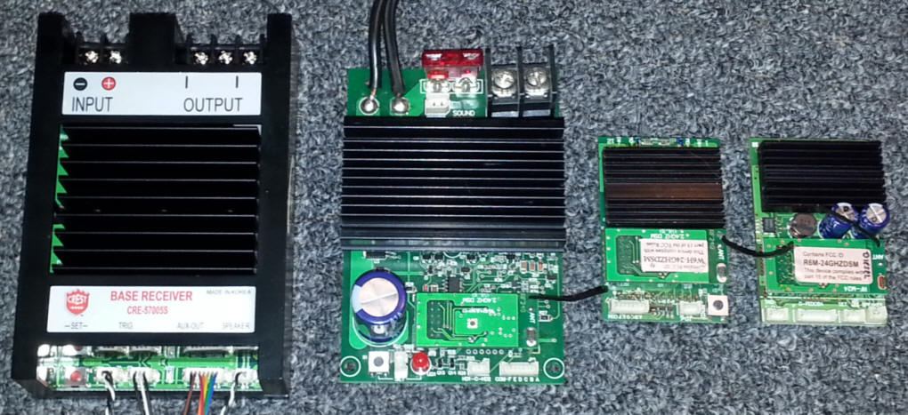
(the Revolution Receiver family portrait - left to right, new Base Receiver, original Base Receiver, original Revolution on-board receiver, latest on-board receiver with sound)
Crest Electronics
Revolution
Base Station / Super Receiver
item # CRE-57005S
revised 06-16-14
(the Revolution Receiver family portrait - left
to right, new Base Receiver, original Base Receiver, original Revolution
on-board receiver, latest on-board receiver with sound)
Introduction
When the first version of Aristo Craft's Revolution Base Unit came out two
years ago I did a review of it and found it to be a very capable unit.
That review is here:
http://www.trainelectronics.com/ART5700TrainEngineerRevolution/TrackSideRevolution/article.htm
A new revision of the Base Receiver is out and is the focus of this article. Operationally they are very similar. Please refer to the first article for details on programming and use as, unless noted otherwise, they are the same with this unit.
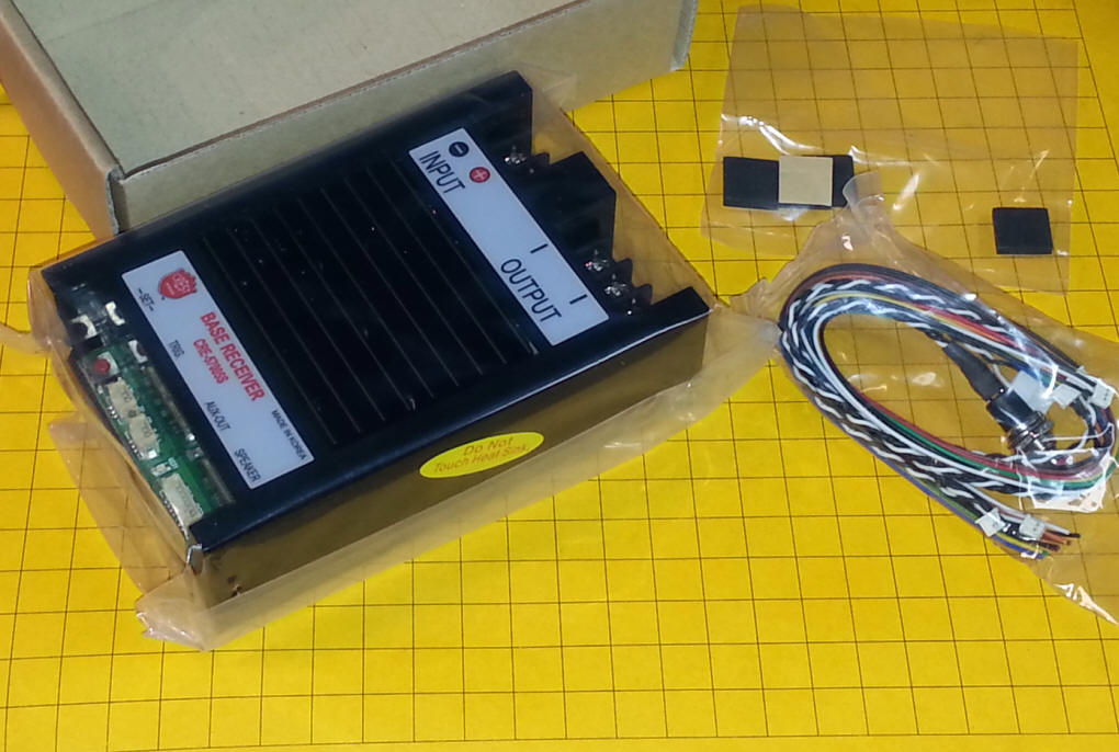
Here is the new receiver as it comes out of the box. The items to the right are self-adhesive "feet" and a set of connecting wires. An instruction manual is not included. It is in PDF format and can be accessed on-line by clicking this link . You can also go to the Crest Electronics support page (here: http://www.crest-electronics.net/support.html ) and select CRE57005S.
What's New? How About A Case and Sound!
For those of us who wanted to use the original unit as a track-side power
controller, perhaps to take the place of our original Train Engineer, the fact
that a proper case was not included created a problem. The new Base
Receiver comes housed in a well designed black plastic enclosure that protects
the circuitry while giving access to all of its power and peripheral
connections. Please keep in mind that this is NOT a waterproof case and the unit must be protected
from the elements.
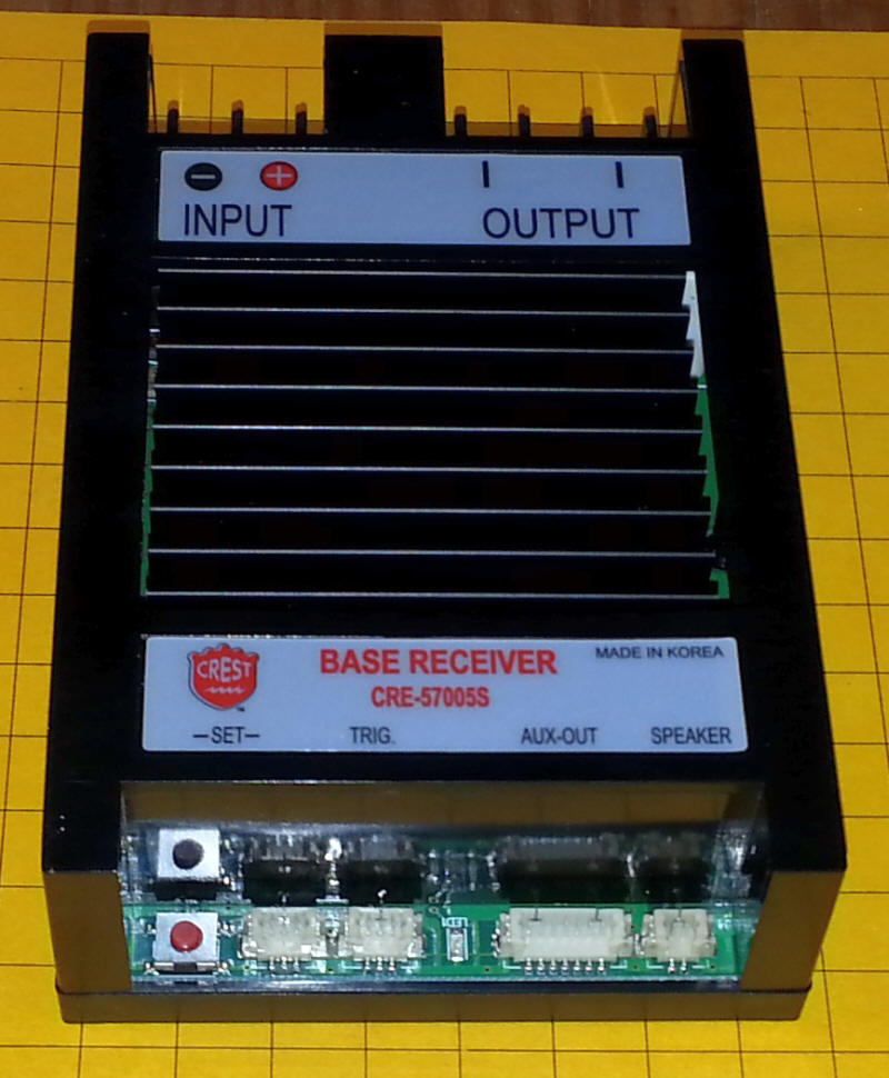
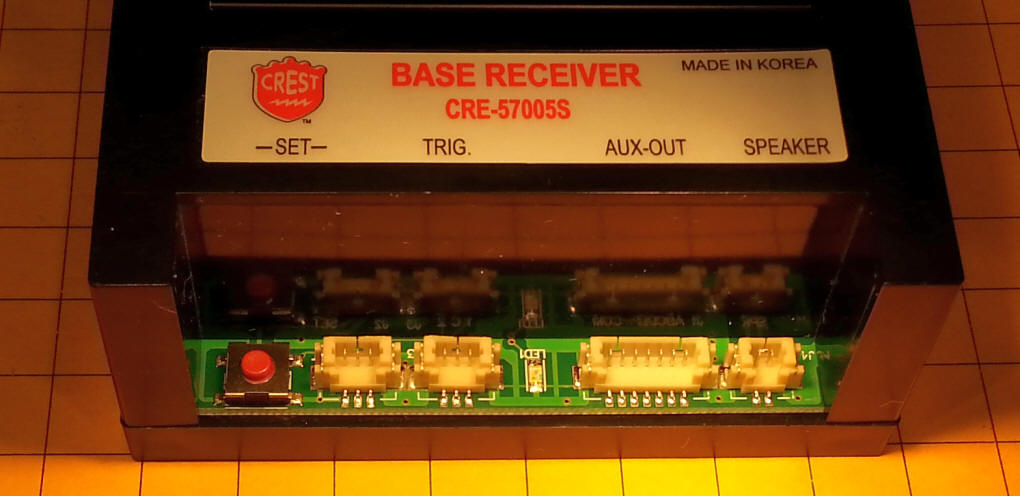
Note that the label above the auxiliary connections includes "TRIG" and "SPEAKER" as this new base unit also includes the same sound capability as the newer Revolution receivers. Notes on how to use the sound capabilities are described here:
http://www.trainelectronics.com/ART5700TrainEngineerRevolution/RevoWithSound/index.htm
The unit I received was set up for diesel sound and uses the same sound files as the standard Revolution receiver. A speaker is not included but any 8 ohm speaker, including those pre-installed in many locomotives, should work well.
Physical Dimensions & Connections
The new unit is just a bit larger than its predecessor. The case is 4
7/16" x 3 1/32" x 1 3/16". The original unit, without a case, was 4 1/8" x
2 3/4" and 1 1/2" high. A large, black heat sink is in the center
of the case.
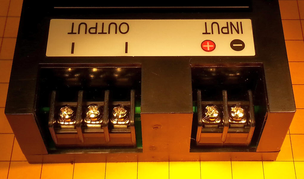
Your DC power supply connects to the two screw terminals marked INPUT. Please be careful to observe proper polarity. The screws are marked "+" and "-". As with the earlier unit connecting the power backwards will not harm the unit, it just will not work until the power is connected with the proper polarity. If the blue LED on the receiver lights for a few seconds you have connected it correctly.
The output connections go either to the track or, if mounted in an engine, to the motor. They are marked OUTPUT. You will note that there are three screws, but that the outer two are the only ones that are used. The center screw is not to be connected.
The auxiliary connections are at the other end of the unit. These connections include, from left to right, a red link button and a place to connect an external link button, trigger inputs for sounds, the seven wire auxiliary output connection and a two wire speaker connection. Please be careful when inserting and, especially, when removing plugs from these connectors. They are soldered to the circuit board and can easily be pulled off if too much force is exerted. Once you plug in the cables it is best to leave them connected. Details on how to use these connections are in the article referenced above. ( http://www.trainelectronics.com/ART5700TrainEngineerRevolution/RevoWithSound/index.htm )
Power Considerations
The unit is designed to operate with a power supply or battery delivering 12
to 26 volts.
A fuse is NOT included in this revision of the receiver. When corresponding with Crest Electronics about this I was assured that the internal circuitry is designed to instantly shut the unit down if a short is detected on the output terminals. I tested this capability by connecting an 18 volt, 3 amp power supply to the unit and putting a screwdriver across the terminals creating a dead short. There was a brief spark and the unit did, indeed, shut down. When the short was removed the power was restored as soon as I increased or decreased the power setting on the transmitter. I did not short the unit with a more robust power supply as I am not a big fan of even bigger sparks and didn't want to fuse anything together!
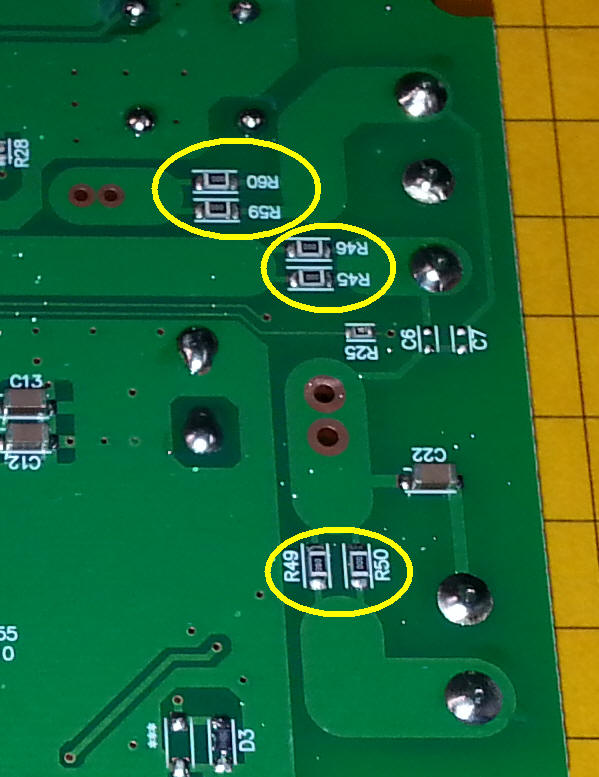
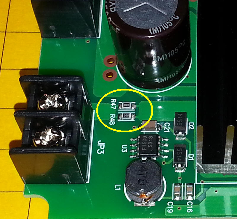
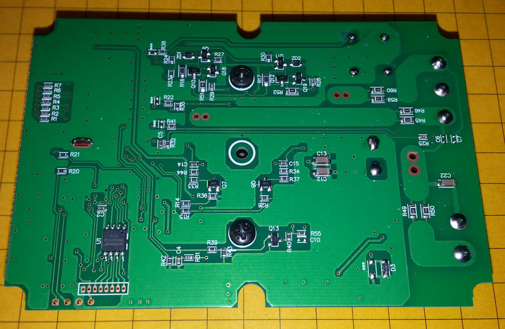
A close examination of the circuit board also reveals that there are eight 0 ohm resistors in line with the input power and output power, two on each connection. I am sure that these are designed to blow if a really high current surge is experienced. They are not the type of thing that most end-users could replace but anyone with experience with surface mount component mounting could replace them.
These resistors are shown here and are labeled as R45, R46, R47, R48, R49, R50, R59 and R60.
Even though the internal protection circuitry works well I would strongly suggest that an appropriate fuse be installed in series with the positive power lead from your power supply. It should be rated at just above the maximum current that you expect to use. Insert an amp meter in line with your power supply to test your setup and largest locomotive. (for how to do this see: http://www.trainelectronics.com/Meter_Workshop/index.htm - read the section titled "Measuring Current")
If, for example, the maximum current draw
is 3 amps use a 3.5 or 4 amp fuse. An appropriate fuse holder is available
from Radio Shack and other sources - for traditional glass fuses see:
http://www.radioshack.com/product/index.jsp?productId=2102786 .
For blade fuses see:
http://www.radioshack.com/product/index.jsp?productId=3150583
Cooling
If you are running a load on the receiver this is in excess of six or seven
amps a fan can be mounted over the heat sink to cool the unit. A 24 volt fan is
available from Crest, it is part number 55499.
Even if you are not pulling large loads be sure to keep the heat sink uncovered and in an open and well ventilated area to prevent overheating.
Conclusion
Crest appears to have addressed any concerns that users of the first Base
Station may have had. It is housed in a well designed case and includes
sound. In my tests the unit operated flawlessly just as the earlier units
have done.
If you have a need for a track side controller or need an on-board controller for a really large engine this is surely the way to go!
---------------------------------------------------------------------------------------------------------------------------------------------------------------
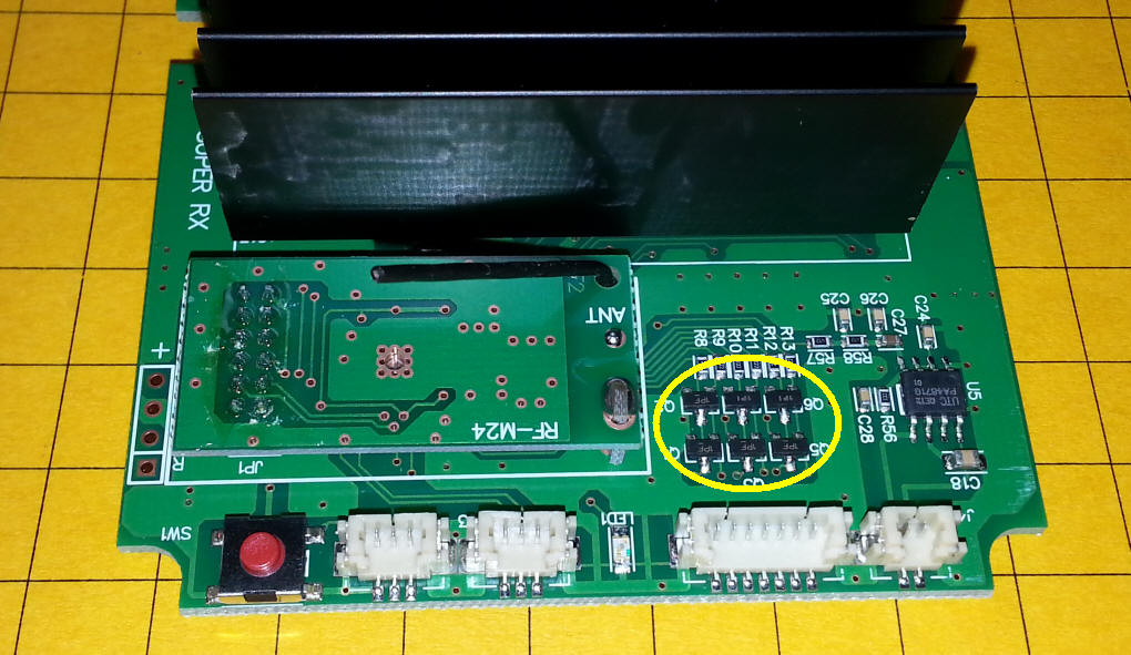
Functional Details
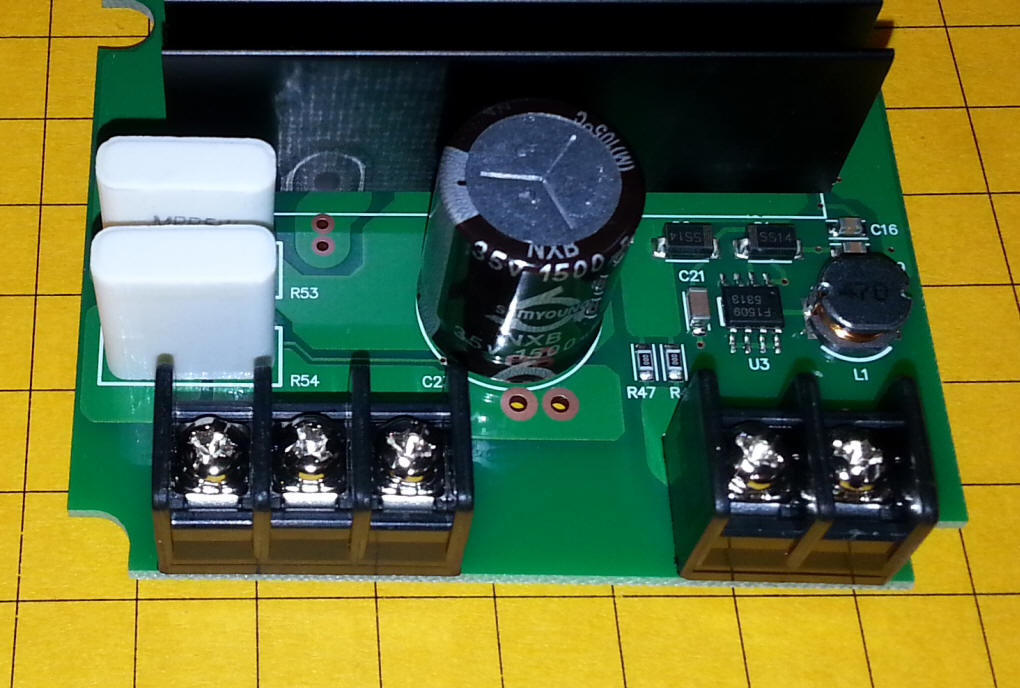
Here the case has been removed as well as the heat sink. Note the thermal material on the bottom of the heat sink that helps to transfer heat from the power components to the aluminum heat sink.
The two ICs at the top right protect against reverse power coming
into the unit and the four at the bottom make up an "H-Bridge". These
devices are N-Channel and P-Channel power MOSFETs. Details on them can be
seen here:
http://www.unisonic.com.tw/datasheet/UT70P03.pdf
P-Channel MOSFET
and here:
http://www.irf.com/product-info/datasheets/data/irfs3004-7ppbf.pdf
N-Channel MOSFET
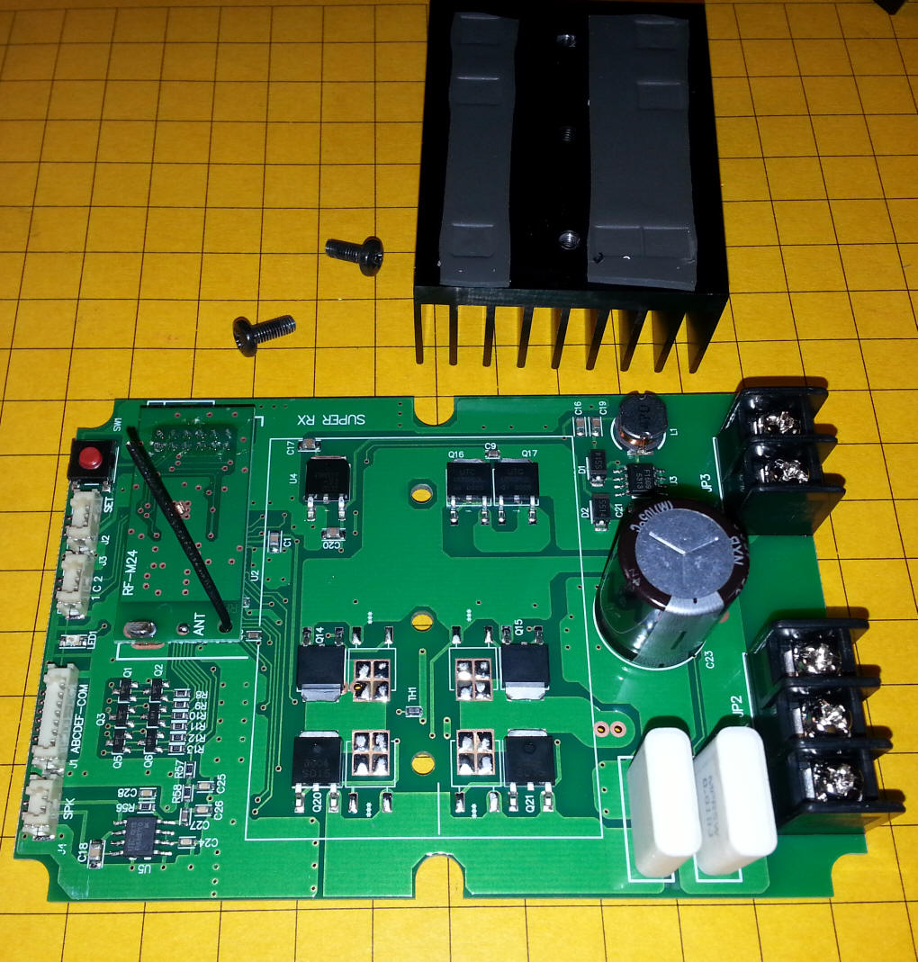
It appears that more current may be available on the auxiliary outputs as a separate semiconductor feeds each output. These devices are circled in the photo.
To the left is the receiver module. Note the small black antenna coming from it.
Filtering of the input power is done here.
Here is a view of the back of the board. Note the two black screws that hold the heat sink in place.
Test Video
This video shows the new receiver under test while operating two electric
drill motors, four Eggliners, two center cab switchers (without bodies!), three
LGB Stainz engines, an LGB Mogul, and a two truck Shay. A total of 16 motors!
The video was taken after running for about 10 minutes.
Power was 22 volts - throughout the test the amperage varied from 7.5 to 8 amps.
The temperature of the heat sink on the receiver, without any cooling, was
always less than 100 degrees.
Throughout the unit worked well. When a derailment took place the receiver immediately shut down.
https://www.youtube.com/watch?v=EA9fXzfIAf4&feature=youtu.be