| There are times when an animation includes
a rotating object that needs power to light a bulb or LED or to
operate a motor or some other DC powered device. This has traditionally been done with slip rings, a set of round contacts and brushes. While this works the brushes or contact surfaces need to be carefully aligned and can wear over time. I have been experimenting with the circuits that are used to wirelessly charge a cell phone and have found a very simple way to use these devices to transfer power wirelessly to a rotating object. |
|
|
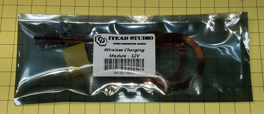
| Parts The circuit I am using was purchased from Itead Studio but is also available from other sources.
I have ordered several other devices and will update this page after evaluating them. The Itead unit is shown here in its packaging...
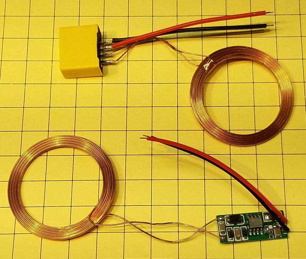
...and the parts within the package. The transmitter is made up of the yellow box at the top and the coil to the right. The receiver is the coil on the left and the circuit board to its right.
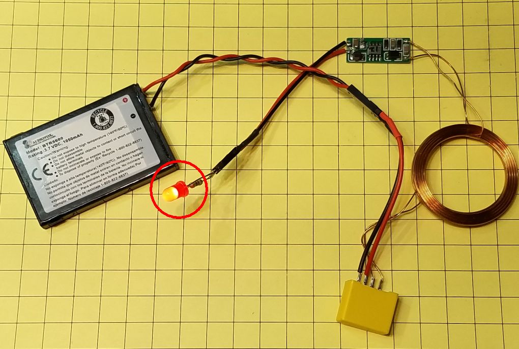
Here a simple test shows that a 3.7 volt cell phone battery will light a red LED (circled) when the two coils are placed one atop the other. Even though the package says "12V" the module works well from 3 volts to 12 volts.
|
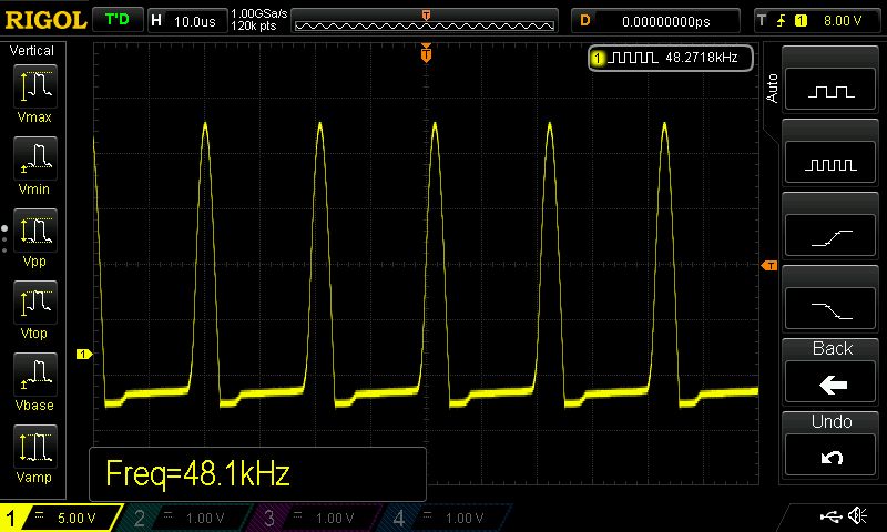
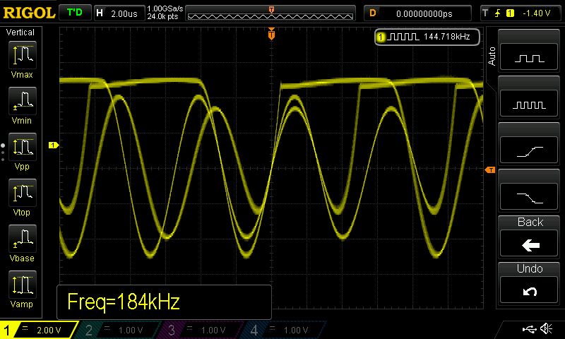
| How it Works It is beyond the scope of this article to go into great detail on how wireless charging works (there are any number of resources on the Internet that do this very well). The short answer is that the circuit on the transmitter (the yellow box in this unit) generates a rapidly changing series of pulses. I measured about 48 KHz (see images below). Those pulses generate a magnetic field which induces a current in the receiving coil. The receiver's circuit converts this energy into a DC voltage which is available through its output. This shot from my oscilloscope shows the pulses that go to the transmitter's coil.
here are the pulses as measured on the receiver's coil, before going through the receiver circuit.
|
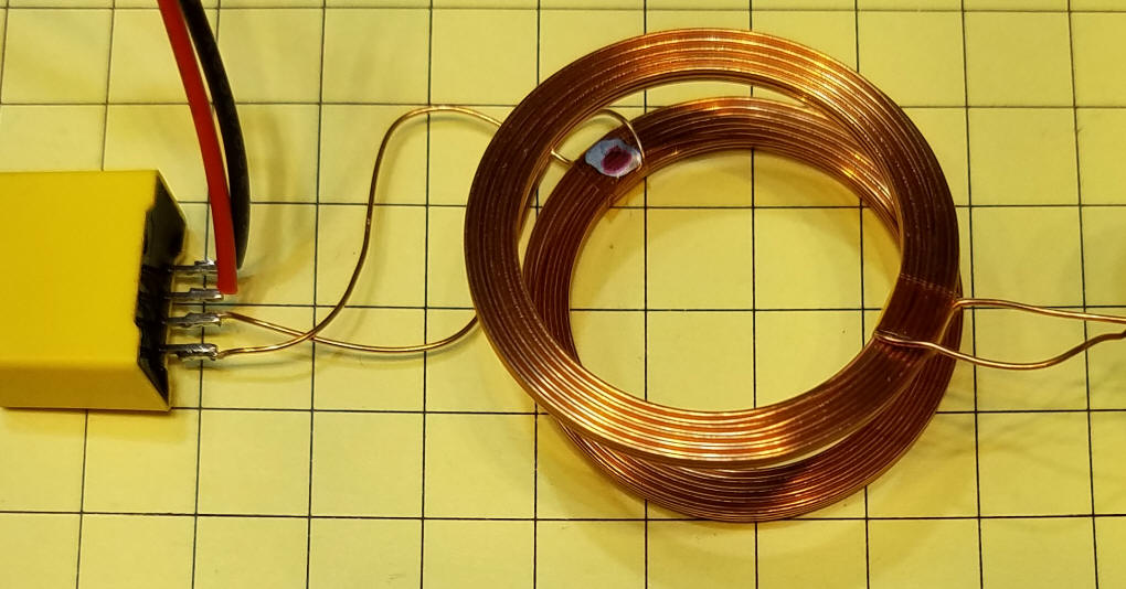
| Loop Orientation I noted that the way you place the coils atop one-another makes a difference in the power at the receiver. With transmitter's coil sitting on my workbench I placed the receiver on top of it and noted the voltage output. Flipping the receiver's coil over either increased the output voltage or decreased it depending on the initial position. I placed a small mark on one side of each coil and made a note of how the worked best. When the two dots are facing each other 12 volts is measured on the receiver's output...
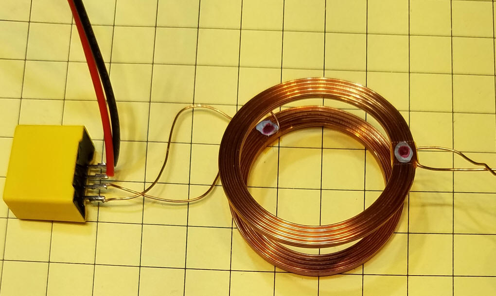
...when the dots are not together (both dots facing up) only 5 volts is seen. Of course, the side that has the dot was chosen somewhat randomly so your dots might need to be in the opposite orientation to get 12 volts.
|
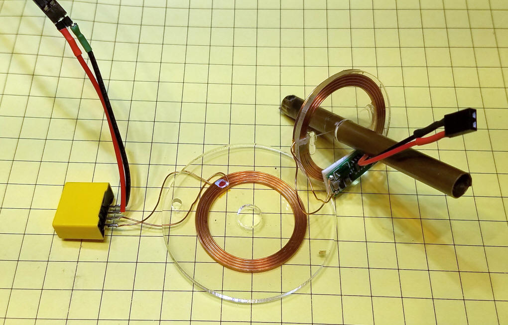
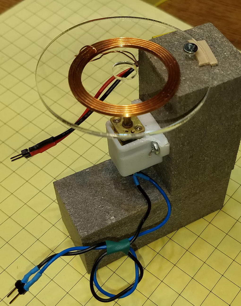
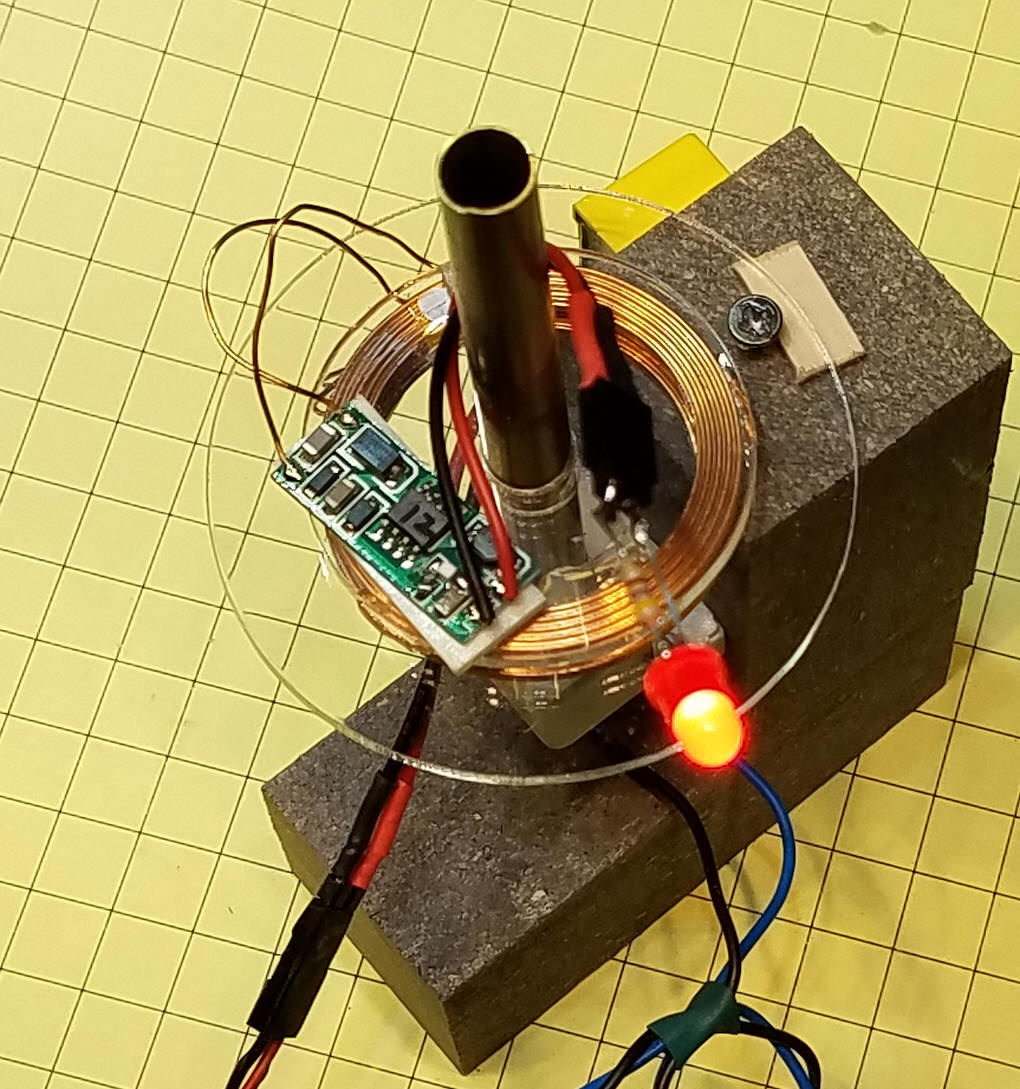
| Building a Demonstration Gizmo I built up a simple rotating shaft with two plastic disks at its base. One disk is physically attached to the base and the other rotates with the shaft.
Here the transmitter's coil is attached to the base that has the motor attached to it as well. (These little gear motors are available here: http://www.banggood.com/N20-DC12V-300RPM-Mini-Metal-Gear-Motor-Electric-Gear-Box-Motor-p-972972.html and from other sources)
The two coils are separated from one another by a 1/16" thick piece of acrylic. Power drops off once the distance between the coils exceeds 1/2". You can compensate for this, to some extent, by increasing the input voltage.
|
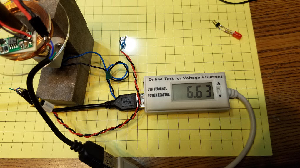
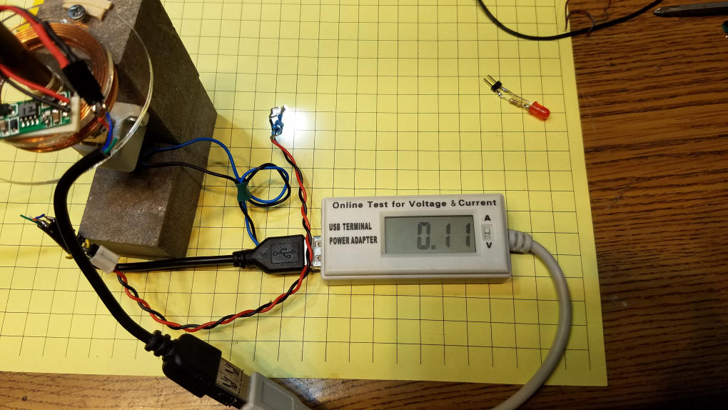
| Current Available The output of the receiver can supply from 5 to 12 volts depending on the input voltage. With an input to the transmitter of 5 volts and a very bright LED attached to the output of the receiver I measured 6.63 volts @ 110 ma demonstrating that receiver has the ability to step up the input voltage.
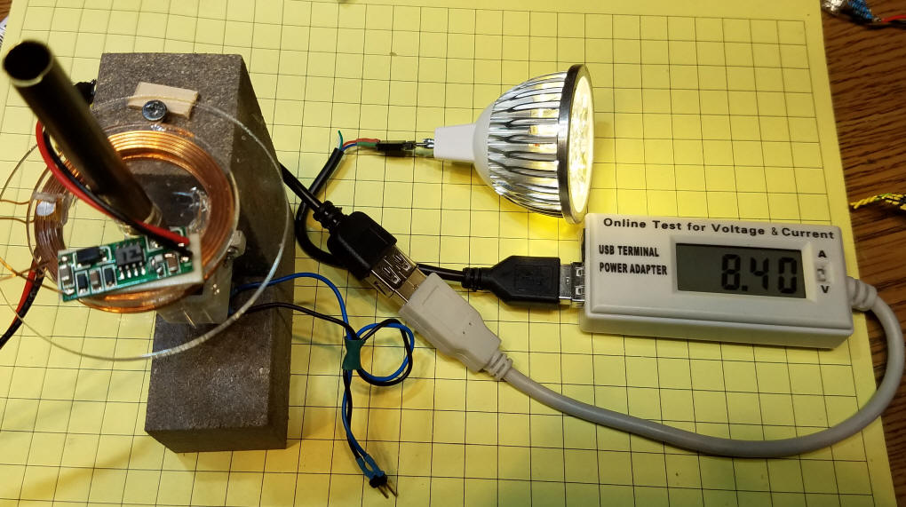
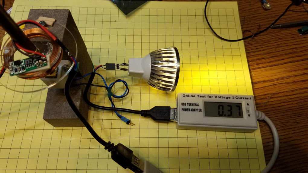
With an input of 12 volts the output was able to light a 12 volt spotlight supplying 8.40 volts @ 370 ma
This is delivering several watts of power - not bad!
This should supply more than enough energy for most of the things that I have in mind for this system. |
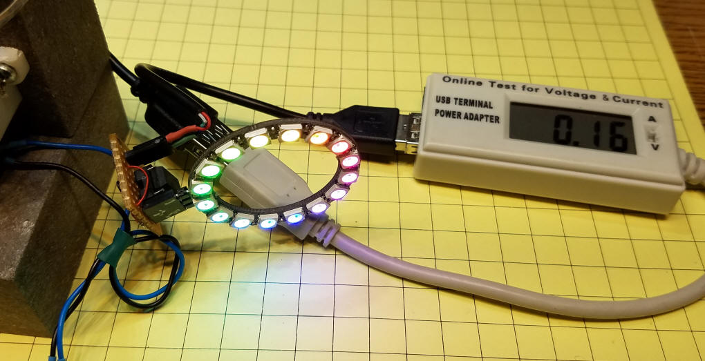
| How Clean is the Output? My last concern was with running microcontroller based circuits from the output of the receiver. As you may know some circuits (Arduino, for example) will not operate correctly or at all if the power you supply is electrically "dirty". I connected an Arduino based circuit that operates 16 RGB LEDs and it worked properly without any issues. A sure sign that the power is clean.
|
| Conclusion I think you can see that this completely solid state method of transferring power to a rotating object can supply consistent, high quality DC power. I plan on using it for a number of animations for model railroads. Please let me know what your applications may be. email: dave@davebodnar.com
|