Timers for Model Railroad Applications
Part II
revised
8-26-12 d. bodnar
| In the first part of this article we explored commercial timers and timers that were based on a 555 integrated circuit. Custom timers, build around a programmable microcontroller, give the most flexibility and the greatest number of options for controlling what happens and when. You can literally program a PICAXE or PIC based timer to open and close one or more relays in any sequence and for any time period you can imagine. You can even make them work randomly so that the same behavior is not seen each time they are activated. |
PICAXE Timer
A PICAXE microcontroller can easily be connected to
a "start" button and a relay that can be used to start and stop a train, a motor,
a sound module
or any other electrically operated device. A potentiometer can be added to the
circuit and be used to adjust the time that the relay remains closed each time
the button is pressed.
There are several advantages to using a microcontroller based timer such as the PICAXE. These include low cost, low parts count, ease of adjustment, flexibility of operation, customization and accuracy. Many hobbyists shy away from anything that you have to "program" but find that it is fast and easy once they give it a try! And don't forget the uncommon pleasure of having "done it yourself!"
The simple timer circuit shown here has only a few
parts but rivals the Omron timer in its capability.
The switch is labeled SW and can be any normally open push button or reed switch. The potentiometer, labeled Pot 1, can be any linear pot with a value from 10K ohms up to one million ohms or more. The relay can be any style with a 5 volt coil. The contacts shown here are DPDT but could be SPST or SPDT as well. Make sure to include the diode D1 as it protects transistor Q1 from damage when the coil on the relay is removed from power as a high voltage spike is generated when this happens. LED D4 and resistor R6 are optional and are there to give a visual indication that the relay has been activated as the LED lights when the relay is active and goes out when it is not..
Here is a simple PICAXE program that will activate the relay whenever the switch is pressed and stay activated for a time period that is set by the pot. Even though there are two other LEDs in the circuit, D2 and D3, they are not used in this program. They will be used to give feedback on the operation of the circuit in the software modification shown next. As the comments indicate the time range is between 0 and 25.5 seconds. If the pot is turned so that its wiper is all the way to the side that is connected to ground it is set to 0 seconds, all the way to the 5 volt side is 25.5 seconds and centered it gives 12.575 seconds. Other times can be set by rotating it a bit more or a bit less. The maximum time range can easily be increased by changing the PAUSE 100 statement to PAUSE 1000. This would give a range of 0 seconds to 255 seconds. If PAUSE 10000 is chosen the range goes to 2550 seconds, about 42 minutes. The only disadvantage of using a higher pause time is that there are still only 255 increments between the minimum and maximum times.
|
'SIMPLE PICAXE 08M Timer Program |
Programming the PICAXE has been explained in detail in other articles that I have written for LSOL (see Robot Trains in the Garden ). Complete manuals and tutorials are free and available from Revolution Education.
PICAXE Prototype
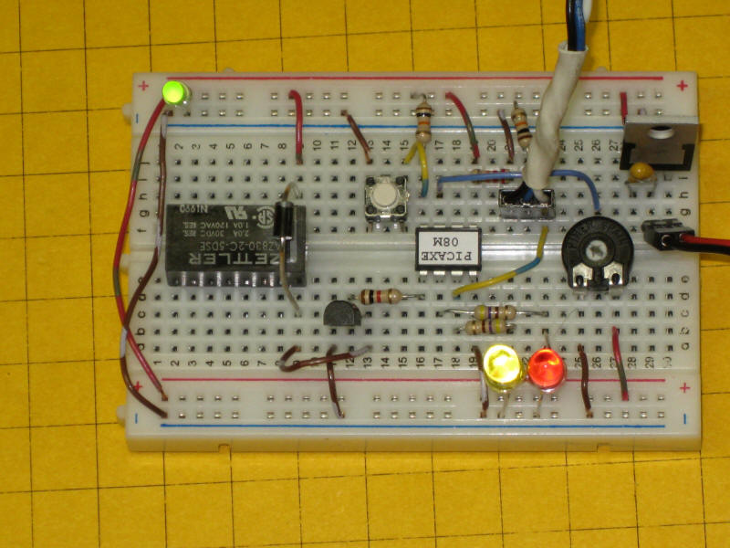
This photo shows the prototype of the circuit constructed on a solderless breadboard like
Radio
Shack's # 273-003. The relay is the black rectangle to the
left. Note the diode that is above it on its right and the transistor near
the relay's lower right corner. The pot is the round black device to the
right. The component with a metal tab in the upper right is the voltage
regulator. The switch is near the center just to the left of the PICAXE
08M. The LED in the upper left is there just to show that power has been
applied to the circuit. The indicator LEDs are in the bottom right.
The circuit faithfully follows the schematic. The only item that is not included is the filter capacitor on the input side of the voltage regulator as it is not needed with the power supply that is being used.
The circuit is shown here soldered to another type of prototyping board which has holes that are spaced the same as those on the breadboard. The potentiometer is in the upper right and is a larger unit than the first one. The trigger switch is at top center. The two-terminal connecting block at the bottom is for power (7-20 volts DC) and the three-terminal block to its right gives access to the relay's common, normally closed and normally open contacts. The cable at the upper left is for programming the PICAXE.
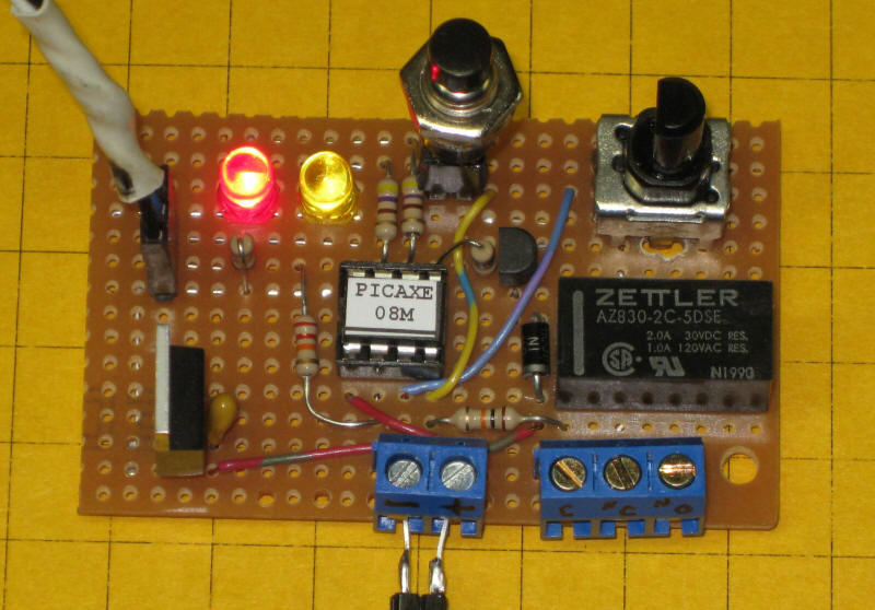
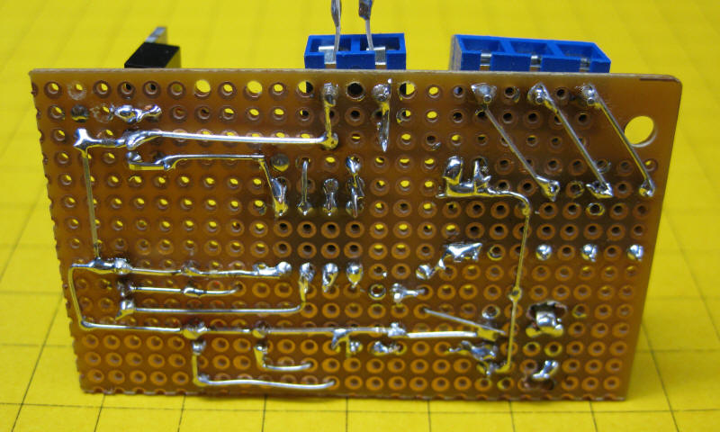
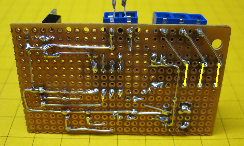
The majority of the wiring was done on the back of the board.
Software Modifications
The first program was very simple but served to test
the unit. The PICAXE 08M has two pins that can connect to LEDs to give us
some feedback on the operation of the timer. The program below uses those
LEDs to show the time that is selected by rotating the pot.
When the pot is turned all the way to the left (counter clockwise) the time is at its minimum and both LEDs are out. When the pot is advanced about 1/4 of the way up the first LED lights, when it gets to 1/2 way both LEDs light. When it gets above 3/4 only the 2nd LED remains lit. When the timer is operating these LEDs light in a similar mode to show when you are in the first, second, third or fourth quarter of the time selected. The LEDs are programmed to flicker when you are setting time and to light solidly when the relay is activated and they are showing time that has elapsed.
The comments in the program should help you to understand how the software works. Remember that the "PAUSE 100" statement gives us a maximum time of 25.5 seconds.
|
'PICAXE 08M Timer
Program
'set time ranges |
This video shows the prototype board in operation and how the pot and the LEDs are used to set the time.
Random Activation
The PICAXE has a RANDOM function that will generate a random number between
0 and 65,535. We can use that function to have the timer activate in a
somewhat unpredictable manner. For example, if we tell the PICAXE to only
activate the timer if the random number that it has generated is below 32,767
(which is 1/2 of 65,535) then it will only activate the timer about one time out
of every two times that the switch is pressed.
|
Side Track: Some of you might
be wondering why the PICAXE uses the value 65,535 when it generates
random numbers. To a computer that is a "round" number as it is 2 to the 16th power minus 1. To a
computer, which "thinks" in base 2, this is quite logical!
|
The first line in the program that involves this is "RANDOM RndWord", which constantly picks a random number and stores it in variable RndWord. A few lines down the program says
IF RndWord > 32767
THEN
Pause 200 'skip 1/2 of the time
GOTO START:
ENDIF
Which redirects the program back to Start if RndWord is greater than
32767 - if
you would like the relay to activate about 1/4 of the time just change
32767 to
16384, which is about 1/4 of 65,535. Note that you do not use commas when
writing large numbers within a program.
|
'PICAXE 08M Timer Program with Random Operation - only activated the
timer about 1/6 of the time the switch is hit 'd. bodnar 6-4-09 SYMBOL LED1 = 0 SYMBOL LED2 = 1 SYMBOL RELAY = 2 SYMBOL POT1 = 4 SYMBOL TRIGGER = pin3 SYMBOL Time = B0 SYMBOL Temp = B1 SYMBOL Range1 = B2 SYMBOL Range2 = B3 SYMBOL Range3 = B4 SYMBOL RndWord = W6 LOW RELAY 'turn power off to relay START: RANDOM RndWord 'reseeds the random number generator Range1 = 255 / 4 'Set point where LEDs will light Range2 = 255 / 4 + Range1 Range3 = 255 / 4 + Range2 ReadADC Pot1, Time Time=255-Time GOSUB SHOWLEDS 'go to subroutine using LEDs to show time PAUSE 25:LOW LED1:LOW LED2:PAUSE 5 ' cause LEDs to flicker when setting IF TRIGGER = 1 THEN START: 'wait for button push IF RndWord > 32767 THEN 'skip 1/2 of the time Pause 200 GOTO START: ENDIF
'set time ranges |
Custom Timer Board
To simplify the construction of the basic timer
circuit that was just described I designed a custom two sided circuit board. Here is the plan for the board. The top
solder layer is in red and the bottom layer is shown in green.
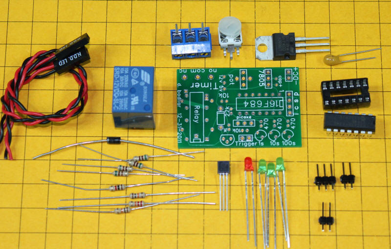
The board and the components used to populate it are shown in this photo.
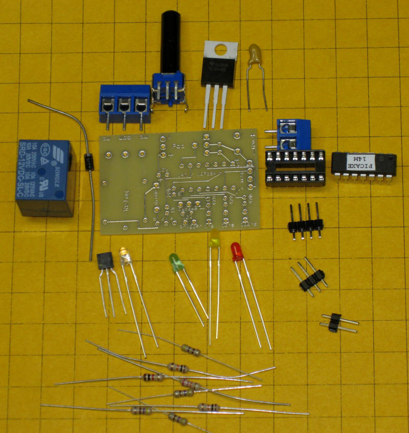
This photo shows the newer board and associated parts.
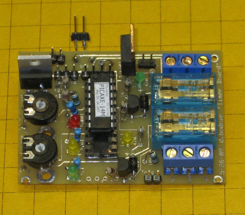
Here is the completed board.
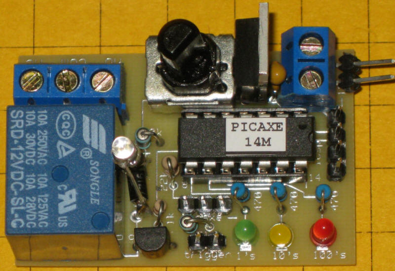
And the completed board using the latest circuit board (dated 10-31-2011) and the newer 14M2 PICAXE chip. Note the two circled areas in the photo. The upper area is labeled "12v" and "5v" - the board is set up for a 12 volt relay. If you are using one nothing needs to be changed. If you use a 5 volt relay cut the trace on the bottom of the board between the 12v hole and the center hole and put a jumper between the center hold and the 5v hole.
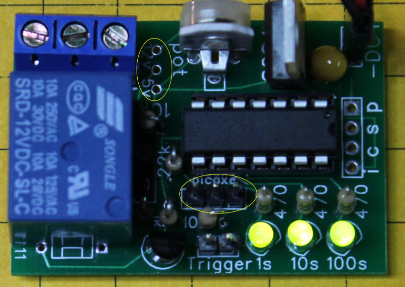
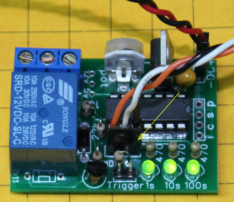
The second circled in the photo above is where the PICAXE programming cable is connected. The black (ground) lead from the programmer goes to the pin on the right, marked with an arrow in the photo below.
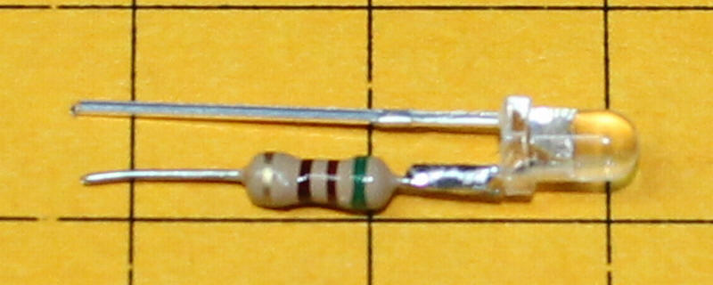
The board does not have a place for an LED that will show when the relay is active but one can easily be added. Solder a 470 ohm resistor to a 3mm LED as shown here. Put the resistor on the anode (positive, longer) lead.
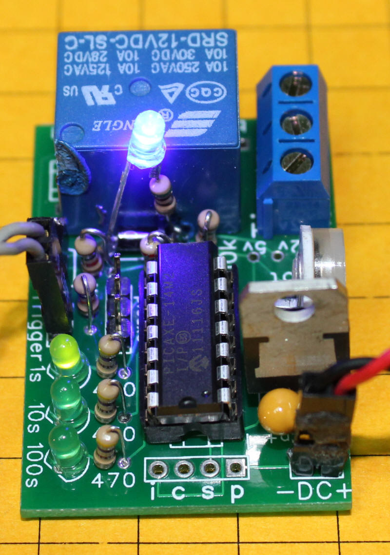
Solder the LED and resistor across the diode with the resistor on the banded end of the diode. It is tricky to do after the relay is in (note the burned mark on the relay!) so it is best to solder before installing the relay.
The board will accommodate either the PICAXE 08M that was shown earlier or the PICAXE 14M. The 14M is almost identical to the 08M in its capability and price but has six additional pins (14 pins rather than the 08M's 8 pins) that we can use to make a more capable timer.
The circuit is also able to use a PIC microcontroller rather than the PICAXE. You may recall that the PIC is the chip upon which the PICAXE is based. The main advantage in using the PIC is additional program memory. The disadvantages are the cost of the programmer that must be used to program it and the cost of the software used to write the programs. The PICAXE needs no special hardware for programming and the software to write the programs is free.
The schematic is similar to the one for the PICAXE 08M. The additions are a third LED and a header for programming the PIC. There is also a connection via pin 13 that can be used to get text based feedback from the PIC through a serial port on your PC. This is invaluable when writing and debugging software.
The program for the 14M utilizes all three of the LEDs and allows us to show seven distinct time steps as we rotate the pot from minimum to maximum time.
| 'PICAXE 14M Timer Program SYMBOL LED1 = 5 'pin 8 SYMBOL LED10 = 4 'pin 9 SYMBOL LED100 = 3 'pin 10 SYMBOL RELAY = 4 'portc 4 pin 6 SYMBOL POT1 = 0 'ADC0 - pin 7 SYMBOL TRIGGER = pin4 'pin3 SYMBOL Time = B0 SYMBOL Temp = B1 SYMBOL Range1 = B2 SYMBOL Range2 = B3 SYMBOL Range3 = B4 SYMBOL Range4 = B5 SYMBOL Range5 = B6 SYMBOL Range6 = B7 SYMBOL Range7 = B8 LOW portc relay START: Range1 = 255 / 7 'Set point where LEDs will light Range2 = 255 / 7 + Range1 Range3 = 255 / 7 + Range2 Range4 = 255 / 7 + Range3 Range5 = 255 / 7 + Range4 Range6 = 255 / 7 + Range5 Range7 = 255 / 7 + Range6 ReadADC Pot1, Time Time=255-Time debug time GOSUB SHOWLEDS 'go to subroutine using LEDs to show time PAUSE 25:LOW LED1:LOW LED10:LOW LED100:PAUSE 5 ' cause LEDs to flicker when setting IF TRIGGER = 1 THEN START: 'wait for button push Temp = Time Range1 = Time / 7 'adjust range based on time chosen Range2 = Time / 7 + Range1 Range3 = Time / 7 + Range2 Range4 = Time / 7 + Range3 Range5 = Time / 7 + Range4 Range6 = Time / 7 + Range5 Range7 = Time / 7 + Range6 HIGH portc relay FOR Time = 1 TO Temp PAUSE 100 GOSUB SHOWLEDS: NEXT Time LOW portc relay GOTO START: SHOWLEDS: 'lights either, both or neither LED based on time IF Time <= Range1 THEN LOW LED1 LOW LED10 LOW LED100 endif IF Time > Range1 AND Time < Range2 THEN HIGH LED1 LOW LED10 LOW LED100 ENDIF IF Time >= Range2 AND Time < Range3 THEN HIGH LED1 HIGH LED10 LOW LED100 ENDIF IF Time > Range3 AND Time < Range4 THEN LOW LED1 HIGH LED10 LOW LED100 ENDIF IF Time >= Range4 AND Time < Range5 THEN LOW LED1 HIGH LED10 HIGH LED100 ENDIF IF Time >= Range5 AND Time < Range6 THEN LOw LED1 LOW LED10 HIGH LED100 ENDIF IF Time >= Range6 THEN HIGH LED1 HIGH LED10 HIGH LED100 ENDIF RETURN |
If you use the newer 14M2 chip the following revision to the program should be used as that chip uses some different designations for pin names.
| 'PICAXE 14M2 Timer Program ' revised for new circuit board dated 12-31-2011 SYMBOL LED1 = b.5 'pin 8 SYMBOL LED10 = b.4 'pin 9 SYMBOL LED100 = b.3 'pin 10 SYMBOL RELAY = c.1 'portc 1 pin 6 SYMBOL POT1 = c.0 'ADC0 - pin 7 SYMBOL TRIGGER = pinb.2 'pin11 SYMBOL TTime = B0 SYMBOL Temp = B1 SYMBOL Range1 = B2 SYMBOL Range2 = B3 SYMBOL Range3 = B4 SYMBOL Range4 = B5 SYMBOL Range5 = B6 SYMBOL Range6 = B7 SYMBOL Range7 = B8 LOW Relay START: 'toggle relay:pause 1000:goto start Range1 = 255 / 7 'Set point where LEDs will light Range2 = 255 / 7 + Range1 Range3 = 255 / 7 + Range2 Range4 = 255 / 7 + Range3 Range5 = 255 / 7 + Range4 Range6 = 255 / 7 + Range5 Range7 = 255 / 7 + Range6 ReadADC c.0, TTime 'TTime=255-TTime 'debug TTime GOSUB SHOWLEDS 'go to subroutine using LEDs to show TTime PAUSE 25:LOW LED1:LOW LED10:LOW LED100:PAUSE 5 ' cause LEDs to flicker when setting IF TRIGGER = 1 THEN START: 'wait for button push Temp = TTime Range1 = TTime / 7 'adjust range based on TTime chosen Range2 = TTime / 7 + Range1 Range3 = TTime / 7 + Range2 Range4 = TTime / 7 + Range3 Range5 = TTime / 7 + Range4 Range6 = TTime / 7 + Range5 Range7 = TTime / 7 + Range6 HIGH Relay FOR TTime = 1 TO Temp PAUSE 500'100=about 30 sec - 500=about 150 sec GOSUB SHOWLEDS: NEXT TTime Low Relay GOTO START: SHOWLEDS: 'lights either, both or neither LED based on TTime IF TTime <= Range1 THEN LOW LED1 LOW LED10 LOW LED100 endif IF TTime > Range1 AND TTime < Range2 THEN HIGH LED1 LOW LED10 LOW LED100 ENDIF IF TTime >= Range2 AND TTime < Range3 THEN HIGH LED1 HIGH LED10 LOW LED100 ENDIF IF TTime > Range3 AND TTime < Range4 THEN LOW LED1 HIGH LED10 LOW LED100 ENDIF IF TTime >= Range4 AND TTime < Range5 THEN LOW LED1 HIGH LED10 HIGH LED100 ENDIF IF TTime >= Range5 AND TTime < Range6 THEN LOw LED1 LOW LED10 HIGH LED100 ENDIF IF TTime >= Range6 THEN HIGH LED1 HIGH LED10 HIGH LED100 ENDIF RETURN |
The board operates as follows:
When the power is first applied the relay is open and the time can be adjusted
The pot is used to adjust the time of operation by turning it right (maximum time) and left (minimum time)
The three LEDs are used to graphically display the time that has been set in seven steps.
When at minimum time all three LEDs are off.
When advanced just beyond 1/7 of the way the first LED illuminates
When beyond 2/7 the first two LEDs light
... 3/7 only the center LED lights
... 4/7 the right two LEDs light
... 5/7 the right LED lights
When beyond 6/7 all three LEDs are lit
If you move the pot left and right the LEDs follow the setting and also appear to move from side to side.
When the trigger switch is closed the relay is activated for the set time.
To indicated how much time has elapsed the LEDs progress from left to right in the sequence outlined above as the time counts down
When the time has passed the relay opens and the unit waits for the trigger switch to be closed again.
While waiting for the next trigger event the time can be once again adjusted
This video shows the more advanced timer in operation
Using the Timer to Operate a Layout
Now that we have a functional timer lets hook some
things up and see what we can do with it. Since the timer uses a relay you
can connect virtually any electrically operated device to the relay contacts and
have it start operating when the button is pressed and stop when the time
expires.
A number of the Playmobil children's playground toys that we animated at Children's Hospital were things that rotated such as playground equipment ...

... and a horse training carousel.

Small geared motors were added to the base of each animated object. We used small 12 volt, 5 rpm motors from All Electronics.
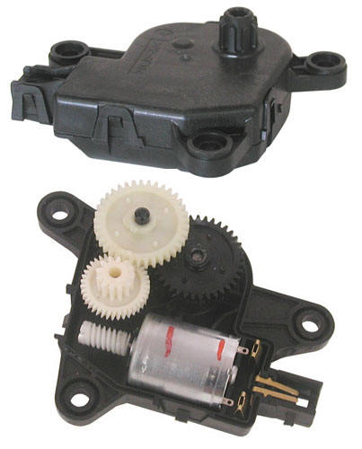
All that was required to complete the animation was to wire the motor to a 12 volt power supply with one of the wires going through the timer's "normally open" and "common" relay contacts. One of the buttons on the front of the layout was connected as the trigger. When a child presses the button the motor starts and runs until the set time expires.
Operating a Train
To have the timer operate a train just disconnect
one of the wires that goes between the transformer and the track and route it through the Common
and Normally Open contacts on the timer. When the trigger button is pressed the train
will start and it will run until the time expires.
If you are operating a large engine or multiple engines you might want to use a relay with more robust contacts. This could be done by replacing the relay in the circuit or just by using the small relay to operate a larger one. You may also have noticed that the relay on the prototype is a DPDT relay and that we are only using half of the contacts. Additional capacity can be achieved by wiring the two sets of contacts in parallel as shown here by the yellow lines.
Station Stop Timer
The timer can be used to have your train
come to a complete stop each time it gets to a particular point on your layout such as a
station or crossing. Several things need to be done to make this
happen:
A reed switch must be placed between the rails on the track to trigger the timer (Click here for information on using reed switches)
A small magnet has to be glued to the bottom of the engine so that it will pass over the reed switch on its travels
A section of track must be isolated from the main line by inserting insulators on both ends of one rail
This diagram shows how it is wired. Note that in this example the train travels from bottom to top on the track, as indicated by the arrow, so that it hits the reed switch before it hits the isolated section of track.
When the engine passes over the reed switch the timer is activated and the section of track is disconnected from power. When the time expires power is restored and the train continues on its way. Notice that we are using the "Normally Closed" contact on the timer board.
Because we have the ability to customize our timer software we can so some interesting things such as:
stop the train every 2nd or 3rd time it hits the reed switch rather than every time it goes by (try to find a commercial unit that will do that!)
add a random routine to the software so that the train stops randomly every 3rd, 4th or 5th time it goes by the station
add a random routine to the timer so that the time that the train remains at the station will be random, perhaps a pause in a range between 30 and 60 seconds.
Going Farther with a Dual Relay Board
The board shown here has two relays, two
potentiometers and two trigger switches. Depending on its program it can
be used as two independently triggered relays or it can be set to operate the
two relays in sequence. Just about anything you can imagine that you could
do with two relays and two triggers could be programmed into it.
Getting Started With Your Own Timer
I can have circuit boards for the relay timer unit made up if there is
enough interest. I also have available all of the parts needed to make the
timers including programmed or un-programmed PICAXE chips. Custom timer
software can also be created to meet just about any need that you may have.
I hope that you have been inspired to try some timer based animation and control on your railroad. It is easy and adds a great deal to the entertainment value of a layout. As usual, please feel free to contact me if you have any questions.