Animate Your Layout With Servos
revised 02-20-08 & 11-10-2015
Link to: Servo Kit Assembly
Click here for video of using the new easier to use servo software: https://youtu.be/1IrPycKqNTI
Nothing brings more life to a model railroad layout than bits of animation scattered here and there throughout the landscape. Visitors may not notice the movement at first but will be drawn back to make sure their eyes aren't playing tricks on them! "Did that door just open?" "I could swear that I just saw one of those prairie dogs pop out of his hole!"
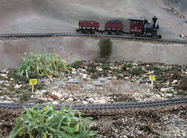
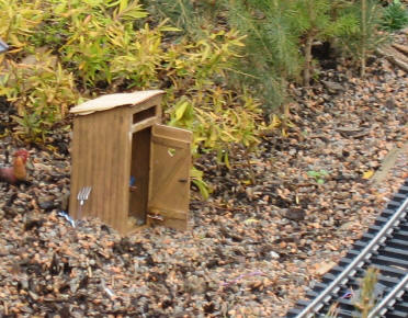
These comments are heard over and over at the new garden railway exhibit at Pittsburgh's Phipps Conservatory. These two simple animations and others add a great deal of interest and realism to the layout. Shortly after the passenger train goes by a secluded farm house a creaking noise is heard as the outhouse door slowly opens. Visitors peer inside to see a cowboy sitting on his throne. Suddenly he sees that he has an audience and the door slams shut to with a resounding thud! At the opposite end of the layout a family of prairie dogs basks in the sun. An observant eye notes that some of them randomly pop out of their holes and then disappear again. What could cause such a thing to happen?
Servos Provide the Magic
Both of these animations are powered by readily available devices that many
of us have used over the years in radio control airplanes, cars and boats.
These vehicles are commonly controlled by servos, small geared motors that
connect to ailerons, elevators, flaps and other steering mechanisms and
throttles in radio
control systems. Even though animation can be achieved using switch motors,
solenoids
and other methods I think you will find that servos provide the most repeatable, reliable, flexible,
powerful and economical method of moving things on your layout.
Servo Basics
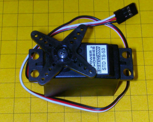
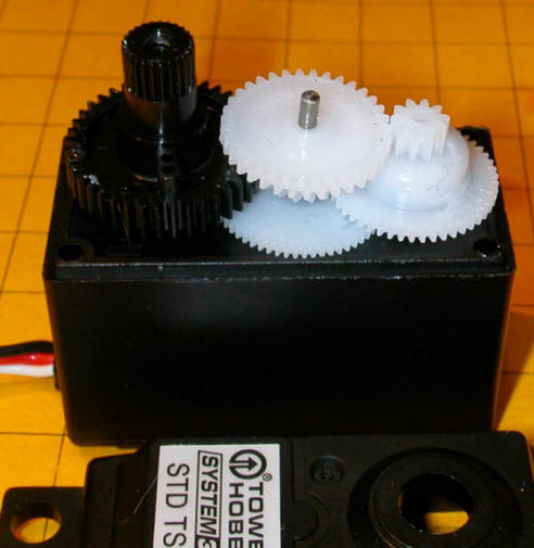
A servo contains a small motor and gear box that rotates a shaft to a
precise location and holds it there. This photo shows a typical servo with
its top removed.
The position of the shaft is based on a digital signal. Most servos rotate through a 180 degree arc while delivering a good bit of torque. Three wires connect the servo to its controller. Two of the wires connect to a source of DC power, normally 5 to 6 volts. The other wire to the servo receives pulses from the controller that tell the servo where to position its shaft. In the photo below the red wire goes to the positive terminal of the power supply, the black wire goes to the negative and the white receives the positioning pulses.

The control pulses are spaced 20 milliseconds apart and the length of each pulse determines where the servo's shaft will come to rest. A 1.5 millisecond pulse will place the shaft in its center position, sometimes referred to as "neutral". A shorter pulse of 1.25 ms will rotate the shaft 90 degrees to the right while a longer pulse of 1.75 ms will rotate the shaft 90 degrees to the left.
In a model airplane radio control system these pulses are generated by the airplane's radio receiver. The length of the pulses is determined by the position of the radio control transmitter's joystick.
This video shows a servo with a digital oscilloscope screen in the background. The square wave on the oscilloscope's screen gives a visual representation of the control pulses. Note that the square wave gets smaller as the servo rotates in a clockwise direction and elongates as the servo rotates counter clockwise.
(Right click the video box below and select "Play" to view)
Servo Control
We could use radio control transmitters and receivers to control the servos
that we use for animation in our layouts but there is a much simpler, more
versatile and less expensive alternative. All we need is a device that can
deliver an appropriate string of pulses to the servo. This can be done
with any number of electronic circuits but the easiest to construct and utilize
may be one utilizing the PICAXE microcontroller. I have written a number of articles
that describe model railroad applications based on the PICAXE including a
Robot
Train, Morse Code Beacon,
Flashing Ditch Lights and a
Lighthouse Controller.
I encourage you to read these articles for more information on the capabilities of this
amazing chip.
Please Note: For those of you who would like to experiment with
servos and don't want to build your own circuitry or program the microcontroller
I have put together a complete unit that is discussed later in this article.
PICAXE Servo Test Circuit
The PICAXE circuit that is used to experiment with servos couldn't be much
simpler.
Pins 1 and 8 of the PICAXE are connected to a 4.5 to 5.5 volt power supply. This can be three AA batteries wired in series or a regulated 5 volt supply. In the circuits we are using here I am using the same power supply for the controller and the servo. This works in most cases but some "noisy" servos cause interference and must have their own, separate source of power. Just make sure that the ground connection from both power sources are joined together.
The third wire from the servo goes to pin 3 (also called out4 for output 4). This pin delivers the control pulses to the servo.
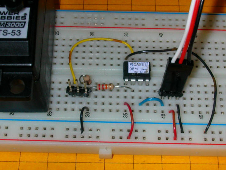
The circuit above is shown in breadboard form below. The servo is to the left and its 3 pin connector is to the right. The 3 pin header between the PICAXE chip and the servo is for programming via the computer's serial port. The two horizontal rows of pins at the bottom are connected to the positive and negative terminals of a 4.5 volt battery pack. Take a moment to confirm that you can identity all of the connections shown in the schematic above as they are made in the photo below.
PICAXE Servo Test Software
The software is equally simple as the PICAXE 08M microcontroller has a built in command that can be used
to position the servo. The command that we will use is appropriately named
"SERVO".
For this exercise we'll just have the PICAXE deliver a range of pulses from
one extreme (1.25 ms) to the other (1.75 ms). This will swing the servo's
arm all the way from its leftmost position to its rightmost. To set the servo's position the command is
SERVO pin, position
where "pin" is the pin that connects to the servo's white wire and
"position" is a number between 40 and 210. 40 sets the servo at
approximately 90 degrees left and 210 places it 90 degrees right. I say approximately
because servo manufacturers differ a bit in the servo's range so some
experimentation may be in order to set the shaft to an exact position.
| Start: FOR b0=40 TO 210 SERVO 4, b0 PAUSE 100 NEXT b0 PAUSE 1000 FOR b0=210 TO 40 STEP -1 SERVO 4, b0 PAUSE 100 NEXT b0 PAUSE 1000 GOTO Start: |
Notes:
|
The program can easily be modified to have the servo move to any position in its range by changing the numbers in the "FOR-NEXT" loop. The speed of movement of the servo is determined by the "PAUSE" command within the loop. The 100 ms pause means that a movement from 40 to 210 will take (210-40)*100 milliseconds or 17,000 milliseconds or 17 seconds. Changing the pause to 10 ms cuts the time to rotate from one extreme to the other to 1.7 seconds.
Using Two Potentiometers to Set Limits
For some applications setting the range of motion of the servo within the
PICAXE software is the best way to go. There are other times, however,
where it is
convenient to be able to adjust the rotational limits without modifying the
software with a computer.
In the schematic above there are two potentiometers connected to the PICAXE through pin 5 (adc2) and pin 6 (adc1). Examine the wiring of the potentiometers, R5 and R6. Note that both have one end connected to +5 volts with the other end going to ground. The center connection, which is controlled by the shaft on the pot, goes to the PICAXE pin. That pin has a variable voltage between 0 and 5 volts on it depending on the position of the wiper on the pot. The two PICAXE pins that are connected to the pots are called ADC pins, this stands for Analog to Digital Converter. In other words these pins can take a variable analog voltage and convert it to a digital number between 0 and 1023. These numbers can be used to set the upper and lower range of the servo. When the pot is turned towards the 5 volt contact the PICAXE "sees" 5 volts and converts that to the numeric value 1023. When the pot is turned to the end closest to ground the PICAXE "sees" 0 volts and reports that as 0. Positions in between 0 and 5 volts are reported as numbers between 0 and 1023. (If you are wondering why the PICAXE uses what appears to be an unusual range of 0-1023 it is because 1023 is an even number to a computer. Remember that computers "think" in binary, base 2, where 1023 = 1111111111 binary.)
The prototype board below has the two potentiometers added to the right of the PICAXE. The pot on the left sets the counter clockwise starting position. The other pot sets the range of motion.
.JPG)
| SYMBOL CCWMax = 200 '225 manual recommended
max SYMBOL CWMin = 30 '75 manual recommended min SYMBOL RangeMax = 170 SYMBOL Temp = b0 SYMBOL Range = w5 'max to min range SYMBOL CCW = w6 'where to start rotation SYMBOL CW = b3 SYMBOL Temp2 = b5 SYMBOL Delay = 15 SYMBOL ServoPin = 4 SYMBOL Trigger = pin3 Start: LOW ServoPin 'relax servo 'IF Trigger = 0 THEN Start ' wait till button pressed GOSUB GetPots: FOR Temp = CCW TO CW Step -1 SERVO ServoPin, Temp PAUSE Delay NEXT Temp pause 1500 GOSUB GetPots FOR Temp=CW TO CCW Step 1 SERVO ServoPin, Temp PAUSE Delay NEXT Temp PAUSE 1500 GOTO Start: GetPots: READADC10 2, Range Range=1023-Range Range=Range/6 READADC10 1, CCW CCW=CCW/6 + 30 Temp2=Range+CWMin IF CCW <Temp2 THEN Skipover CW=CCW - Range MIN CWMin GOTO Skipover2 Skipover: CW = CWMIN Skipover2: RETURN |
Notes:
|
Adjusting the Servo Position
To adjust the servo turn the potentiometer that is connected to pin in1, CCW
in the program, all of the way towards the positive terminal. Turn the
other potentiometer, called Range, all of the way towards its negative terminal.
This sets the servo to start at its leftmost (most Counter Clock Wise) position
and rotate to its maximum range. If the CCW pot is turned to the right the
maximum CCW position is moved more to the right. Moving the Range pot to
the left decreases how far the servo will move. Adjusting the two
pots will give you complete control over the starting and ending point for the servo.
Triggering the Servo
The remaining input pin, Pin 4 (also called in3), is used for triggering the
servo. It can be connected to
any type of normally open SPST switch. For the Phipps layout I
triggered the action in the outhouse with a
reed switch
that closes when a
magnet glued to the bottom of the engine passes over it. The switch
briefly connects Pin 4 (in3) to + 5 volts. When the switch is released
resistor R4 immediately pulls the pin to ground. When a PICAXE pin "sees"
+ 5 volts it's value is "1". When it is connected to ground and "sees" 0
volts it's value is "0".
The only programming change that is necessary is to remove the apostrophe from the line (about 12 lines down from the top) that reads:
IF Trigger = 0 THEN Start ' wait till button pressed
You may remember that in programming the apostrophe makes the line a remark not a command that will be acted upon. Removing it activates the command. If Trigger = 0 the button is not pressed and the program goes back to the "start" location. When the button is pressed the value of "Trigger", which is just another name for "pin3" becomes a 1 and the program continues. Simple!
Sound with Motion
You might think were are completely out of pins on the PICAXE but pin 7
(also called out0) can be asked to do double duty. Under most
circumstances pin 7 is connected to the programming cable. It can be used
as an output pin as well. The output device is this case is a
digital sound card that can be triggered as the servo is activated. I have
had very good luck using digital sound recorders from
Electronics 123. The unit I
use is
A96010 which is available for less than $10.00. These and other sound
boards are discussed in some detail in
another article that deals with sound and model railroads. As you can see in the schematic below the sound recorder
module only has a few connections. Power for the unit can be up to 6 volts
so it works well with the 5 that we provide for the PICAXE board. Two
wires are for a speaker or, in our system, an amplifier that gives much greater
volume. The sound starts when a button is pressed or when the PICAXE
activates the board through the button's connection.
Notes on the schematic:
The only software change is the addition of code to toggle the state of pin Out0 so that the sound is started at the right time. In the example program below the sound is started as soon as the button is pressed. The changes are highlighted in bold type. Even though you might think that the placement of the LOW Audio command is critical as it could stop the sound prematurely, this is not an issue as the sound will start and continue playing to its end no matter when the audio pin's state is changed. Just make sure it is located somewhere in the program where it will be invoked before the sound clip is completed or the sound will start over again.
| SYMBOL CCWMax = 200 '225 manual recommended
max SYMBOL CWMin = 30 '75 manual recommended min SYMBOL RangeMax = 170 SYMBOL Temp = b0 SYMBOL Range = w5 'max to min range SYMBOL CCW = w6 'where to start rotation SYMBOL CW = b3 SYMBOL Temp2 = b5 SYMBOL Delay = 15 SYMBOL Audio = 0 SYMBOL ServoPin = 4 SYMBOL Trigger = pin3 Start: LOW ServoPin 'relax servo IF Trigger = 0 THEN Start ' wait till button pressed HIGH Audio GOSUB GetPots: FOR Temp = CCW TO CW Step -1 SERVO ServoPin, Temp PAUSE Delay NEXT Temp LOW Audio pause 1500 GOSUB GetPots FOR Temp=CW TO CCW Step 1 SERVO ServoPin, Temp PAUSE Delay NEXT Temp PAUSE 1500 GOTO Start: GetPots: READADC10 2, Range Range=1023-Range Range=Range/6 READADC10 1, CCW CCW=CCW/6 + 30 Temp2=Range+CWMin IF CCW <Temp2 THEN Skipover CW=CCW - Range MIN CWMin GOTO Skipover2 Skipover: CW = CWMIN Skipover2: RETURN |
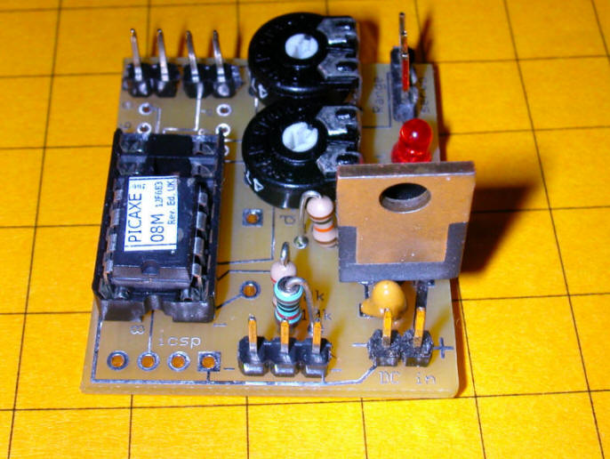
Custom Circuit Board Simplifies Things!
In order to make experimentation with servos simpler for me and others I
designed a custom circuit board and had a few fabricated. The board is
based on the schematic we have been using but has some features that will not
be used at this time. Here are four photos of the unit from all angles.
If you are interested in using one of these boards please drop me an email
(dave@davebodnar.com ) to inquire
about price and availability.
The unused pins in the PICAXE socket are there because the board can also
support the PICAXE 14M which has six additional pins.
.JPG)
If you look carefully at the photo below you will see that the potentiometer closest to the edge of the board is labeled "Range". The board has a voltage regulator on it (lower right in the photo) so that DC power between 6 and 12 or more volts can be used to power the unit. If you are going to feed it with much more than 12 volts the regulator will get hot and a heat sink may be needed. The programming cable goes to the header in the bottom center.
The other pot is clearly labeled "Start" in this photo. The servo connects to the three pin header at the lower right. Its black wire goes to the left onto the pin marked with a "-" symbol.
.JPG)
The sound board connects to the pins labeled "Sound". You can also connect an LED, with appropriate current limiting resistor, to the "Sound" pins. The "Trigger" connects to a switch is located in the lower right. The 7805 voltage regulator is clearly visible in the upper left.
.JPG)
Mechanical Connections
So far the focus of our discussion has been on controlling the rotation of
the servo's shaft. Next we have to look at how one can transfer this
rotation to make our animation do something interesting.
This short video shows the finished outhouse atop its base. The animation starts when a giant hand presses a small button!
(Right click the video box below and select "Play" to view)
In the next video, taken at Phipps, the animation is activated twice. The first activation is because of the train going over the reed switch. The second time a magnet is manually moved across the reed switch. Can you tell it was windy the day this was filmed!!??!!
(Right click the video box below and select "Play" to view)
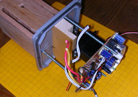
The two photos below show an outhouse that is mounted on top of a plastic utility box that will be buried underneath the outhouse.
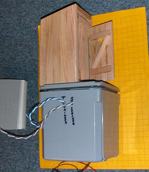
The box, a 4" x 4" x 4" electrical box from Lowes, is waterproof and houses the servo, PICAXE board, sound board and an amplifier from an old PC speaker system
The wires exiting the box are for an external speaker, trigger connection that goes to a reed switch on the track and a source of external power. The power wires come in from the bottom through holes that are left unsealed. This allows any water that might get in to escape from the bottom of the box.
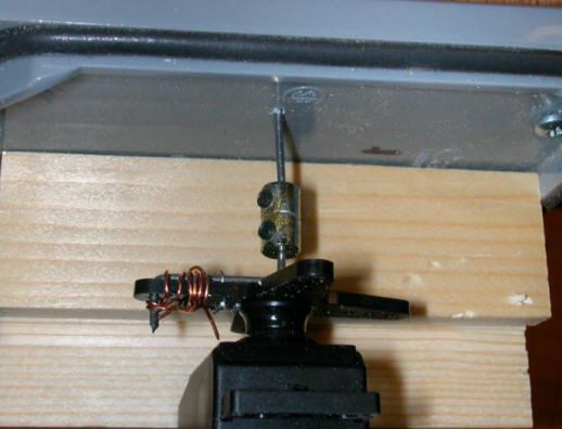
Outhouse Construction
The mechanical connections are very straight forward.
The door is opened and closed by a thin piece of piano wire that extends from
the door down into the control box. The following set of photos will give you an idea of
how it is constructed.
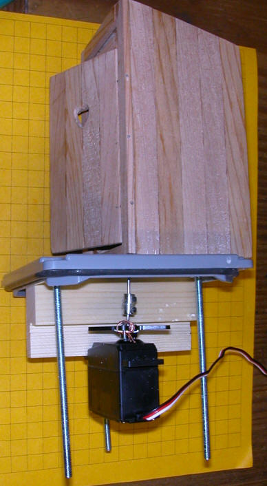
The outhouse and servo are both mounted to the top of a plastic box. The servo is screwed to the piece of pine that is just behind it. Note the gasket on the bottom of the lid that helps to make the top of the box water tight.
The wire that goes from the servo to the door is bent at both ends. One end goes onto the servo's horn, the other (seen at the right) moves the door.
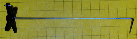
It is much easier to install the wire and pass it through the base if is cut into two pieces that can be reattached after installation. I didn't have a proper fitting to join the pieces back together so I soldered several model airplane wheel locks together. That gave me a sleeve with set screws to attach the pieces of wire together.
This close up view shows the model airplane hinges that are used to join the outhouse and the door. The rod that connects to the servo can be seen behind the top hinge.
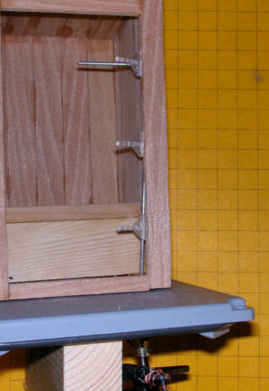
The hinges are inexpensive and make connecting doors a snap.

Here the hinges are about half way into the door. When fully inserted and glued they are nearly invisible.
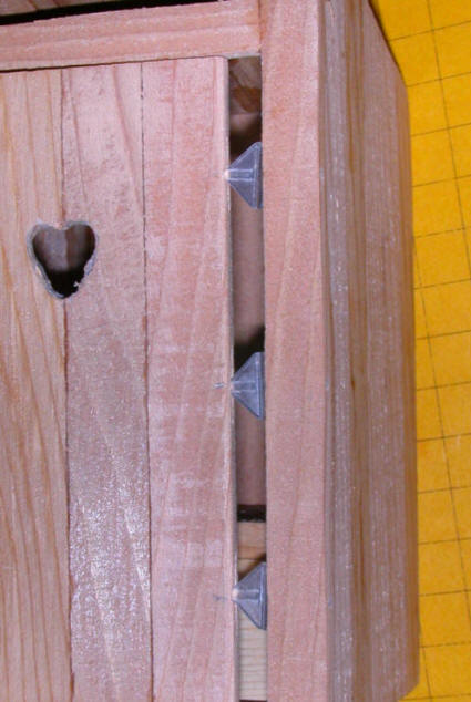
The rod goes into a hole in the top door brace. When the servo rotates the rod the door opens and closes.
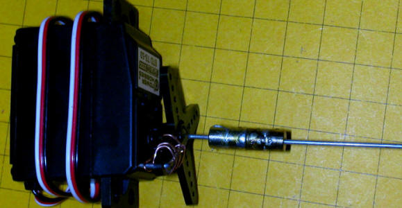
The coupler makes removing the servo and/or outhouse a simple task. The piece of piano wire at the bottom is connected to the servo's horn with wire and is centered on the servo's shaft.
Three bolts attach the amplifier that is seen below the servo. The amplifier was salvaged from an old set of computer speakers and fit in perfectly after a bit of trimming. The loose wires are from the original connections to the speakers and will be redone.
The PICAXE circuit board, on the right, and the sound card, on the left, are mounted high and (hopefully) dry at the top of the unit. Notice that the board used here is not one of the custom boards shown above since this animation was made before the new boards were designed.
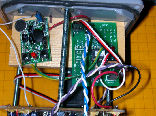
The speaker is mounted externally behind a nearby shed. It is close enough to the outhouse and far enough from visitors so that the sound seems to be coming from the outhouse itself.
Prairie Dog Animation
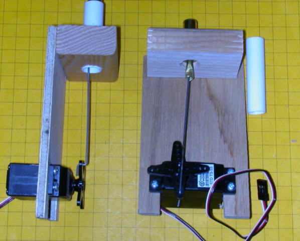
Each member of the group of animated prairie dogs is operated by an individual servo. The parts that were
used to make one prairie dog unit are shown below.
The unit on the left is complete. It will be mounted under the lid of a box whose top is flush with the terrain on the layout so that only the small tube shows above ground. A carved and painted prairie dog is placed into the brass tube that is moved up and down by the servo.
The parts that were used to make it are on the right and include:
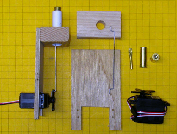
Here you can see how it is all assembled.
When the servo rotates in a clockwise direction the cartridge goes up lifting the prairie dog that is attached to the cartridge above the ground. When it turns the other way the cartridge is pulled in lowering the prairie dog.
This design, requiring a separate servo and controller for each animated animal, is the third, and most successful, of my experiments. The first used multiple cams, just like in an automobile's valve mechanism, to lift the prairie dogs. A motor turned the cam shaft and springs were used to return them into their holes. The second used a crankshaft, also found in automobile engines. Both designs were rejected for two reasons. First was the amount of power that was required to rotate the cam shaft under the stress of the springs. Even the crankshaft design, that used no springs, needed a powerful motor to keep things humming. The other, and more significant, drawback of both designs was that the prairie dogs always went up and down in the same sequence, just like a car's valves or pistons. There was no variety in movement. Prairie dog behavior dictates that all will be below ground at some time, especially if they are frightened. Neither of these systems provided for that.
The servos took care of all of the problems as the sequence of movement wasn't tied to a single piece of hardware but to the computer program that ran the independent servos. Power was no longer an issue as each prairie dog has its own motor. If one failed or faltered the others would keep on working.
In this video you can see the prairie dog motor and lift mechanism along with the square wave on the oscilloscope.
(Right click the video box below and select "Play" to view)
Any number of animated animals can be controlled by separate PICAXE 08M chips or as many as six can be simultaneously controlled by another of the PICAXE chips that has more pins available.
This video shows a single 18 pin controller operating six servos. The
large capacitor, the blue cylindrical object, is needed to keep the system
working under the strain of all of the motors being operated at once. A
similar system is used with the prairie dogs at Phipps Conservatory.
There, of course, the prairie dog's motion is random rather than this
choreographed "dance"!
(Right click the video box below and select "Play" to view)
Here you can see the prairie dogs themselves moving up and down on the layout. You will have to look carefully as they are tiny little fellows and blend into the background!
(Right click the video box below and select "Play" to view)
Water Tower Spout Animation
I have added spout movement to several Aristo Craft water towers. In each
case the servo was mounted under the floor of the water barrel and a thin
stainless steel rod was run to the spout. I made a mock up of such a water
spout to show the flexibility and ease of adjustment of the two potentiometer servo circuit that
we have been examining. It is shown in the video below. In the
interest of time the speed of movement of the spout is fairly fast but could
easily be slowed to a more prototypical speed by inserting a longer pause
between each servo step in the software.
(Right click the video box below and select "Play" to view)
Obviously you would not want to mount the servo below the spout as in this example but it is easily shifted to an out-of-the-way location.
Servo Reliability
The question that I am sure has crossed your mind as you read this is:
"How does
such a simple device hold up to bad weather and continuous duty?"
I am
happy, and somewhat surprised, to be able to report that the prairie dogs and
the outhouse have been operating daily at Phipps Conservatory since November 1,
2007. They have not shown any signs of failure nor have problems
cropped up over a rather cold and
wet Pittsburgh winter. I built backups for both animations in
expectation of replacing one or both within a month or two but that has not yet
been necessary. Hot summer weather may take its toll but so far, so good!
Other Animation Ideas
As you can imagine there are dozens and dozens of things around a garden
railway that can be animated with servos and some simple mechanical linkages.
Some of the other things I have used servos for include:
Things that I have considered but not yet done include:
I am sure that you have ideas, too! After all, the only limit to what you can do is your imagination!
Please let me know your thoughts & ideas and if I can be of assistance.
Link to: Servo Kit Assembly