|
|
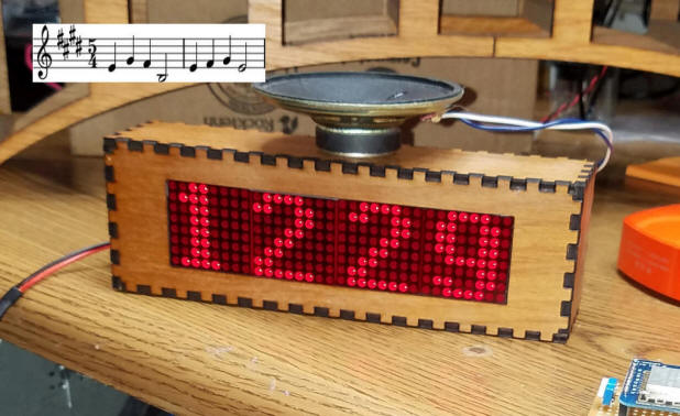
| Introduction I have built a number of clock circuits over the years. I recently modified a WiFi connected digital clock so that it would play Westminster chimes on the quarter hour, half hour and so on. This clock is described on my web page here: http://www.trainelectronics.com/Arduino/LED_Matrix/Chimes/index.htm, on Instructables and on YouTube.
A digital clock with Westminster chimes is an interesting device but it really lacked one thing that you would expect to see on such a clock, HANDS! This realization brought me to the present clock implementation. I can't say that it was the most difficult project I have undertaken but it is surely one of the most time consuming (no pun intended). With most projects one can make a change to the software code and test it immediately. With this clock the best case was needing to wait for the minute hand to pass 12 (which took up to 59 minutes) or the worst case was waiting for a full day to pass before I could determine if the code change worked as expected. There were a number of things that enabled me to complete this clock project:
I think you will find the end result to be an interesting & pleasing clock. I hope gives you as much satisfaction as it has given me. If you build one please send me a photo and your impressions of the unit. While the code provided here does work well I am also sure that it can be improved. If you make any changes to the code that you would like to share please let me know. |
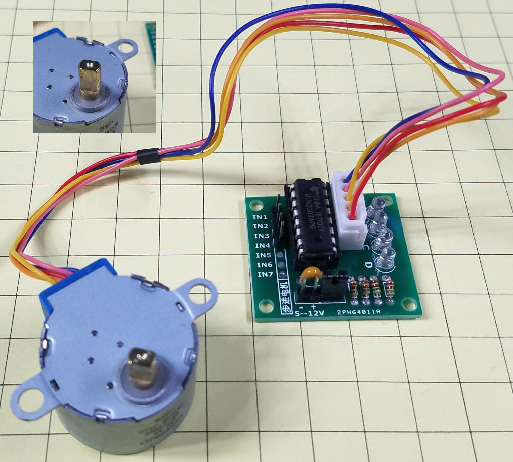
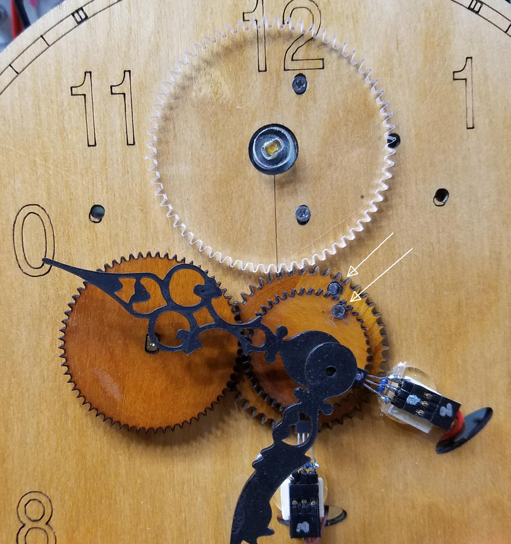
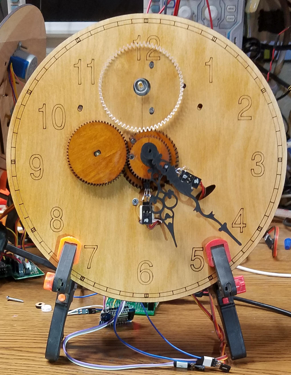
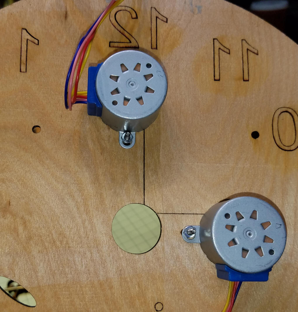
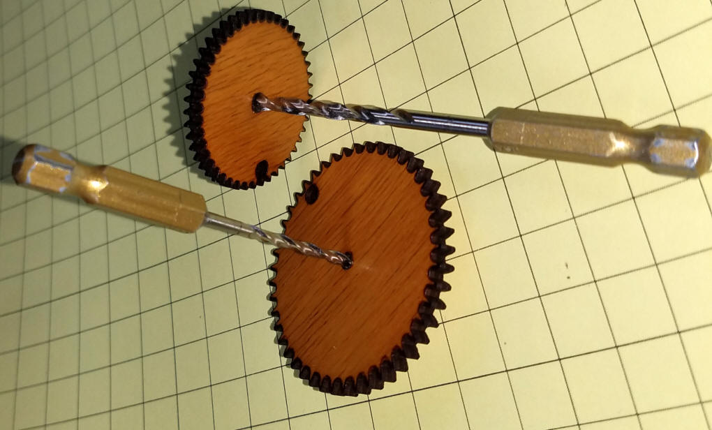
| The Hands Mechanism The two hands are animated with two small, geared stepper motors that I purchased from Amazon (see parts list). They come with driver boards that connect to four pins on the Arduino. I was able to use eight adjoining pins on the Arduino so connections are rather simple. In addition the driver boards need power. They are rated at 5 volts but I found that I could connect them to 7 volts to gain torque. If you are fortunate enough to build a low friction set of gears you can get away with 5 volts. 7 volts doesn't seem to do any harm as the motors are only powered on for a very short time every few seconds. The drive shaft of the stepper motor is flattened on two sides to facilitate attaching to a gear, see upper left inset.
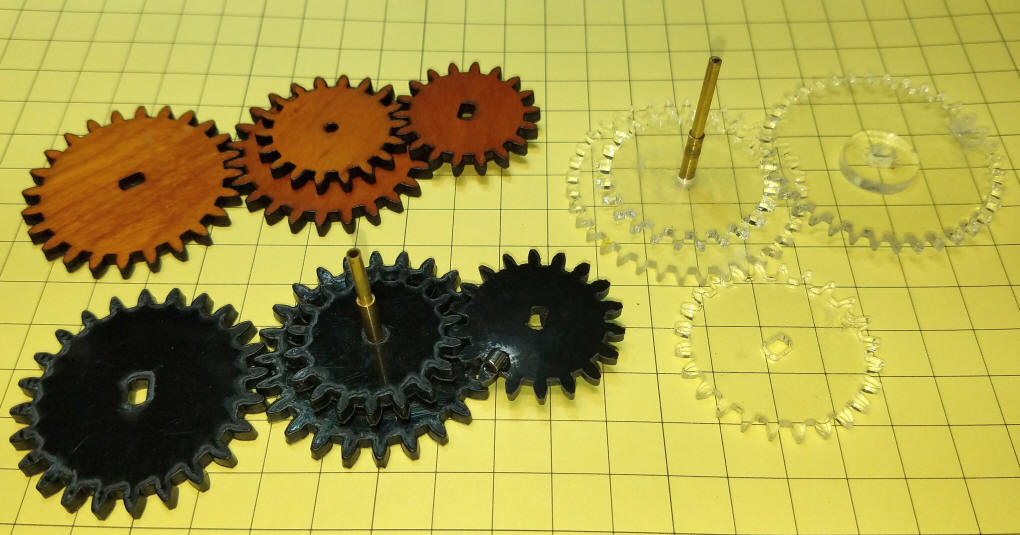
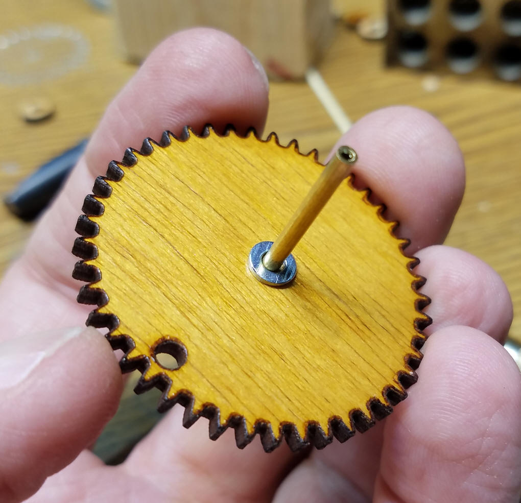
In order to have two hands on the same central shaft I used two sections of brass tubing that fit one inside of the other. The outside diameters of the tubing are 1/8" and 3/32". In my first prototype these shafts were super glued to the center of two gears as shown here. The gears with the oval shaped cutout press onto the shaft on the stepper motor and the others are supported by the concentric brass shafts. I have made gears from plywood, upper left, clear acrylic, upper right, and Delrin, the black ones.
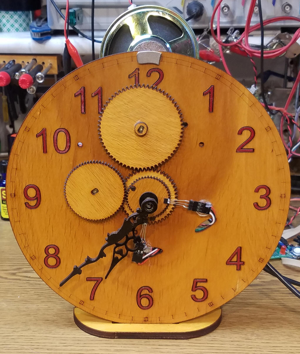
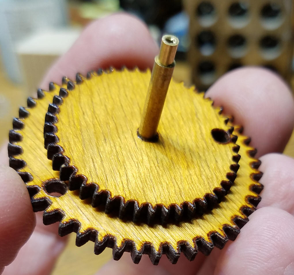
The gears that go from each stepper motor to the gears on the shafts are in a ratio of 1:1, which means for every step the stepper motor moves the gear and its associated shaft moves the same number of degrees. Here lies the first major issue I ran into. The stepper motors are geared to improve torque and accuracy. The gear ratio in them determines the number of steps that must be completed to do one revolution. For these motors this turns out to be 512 steps per revolution. Why 512? If you deal with computers and programming you may have an idea as 512 is 2^9 (two to the 9th power), a nice "round" number to a computer. I had a devil of a time getting the clock to move its hands correctly because 512 does not divide by the number of minutes in an hour (60) or any of the numbers associated with time keeping. I did get the code to work but every hour I had to skip ahead a few ticks of the hands to keep proper time. Since I had the ability to make gears of any size or tooth configuration it occurred to me that I could change the number of steps per revolution from 512 to something more "clock friendly" like 360. If I attached a 512 tooth gear to each stepper motor and a 360 tooth gear to each gear on the central shaft it would take six ticks of the stepper to move one minute with no more hourly adjustment issues! Problem solved & code simplified. My current gear setup is shown here. You should be able to see that I didn't use a 512 and a 360 tooth gear, but a 64 tooth and a 45 tooth. A little math will tell you that the ratio is the same and the gears are stronger with larger teeth. (512 / 360 = 1.42222... and 64 / 45 = 1.42222...) The white arrows point to the two small rare-earth magnets that allow the Arduino to know the position of the hands. More on that later.
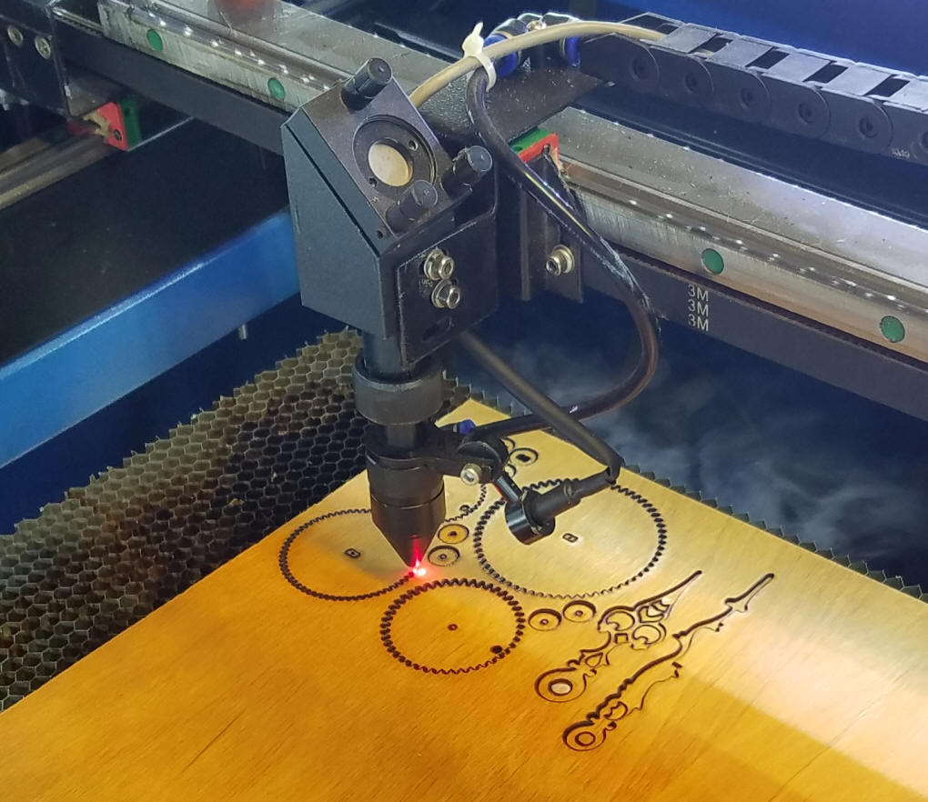
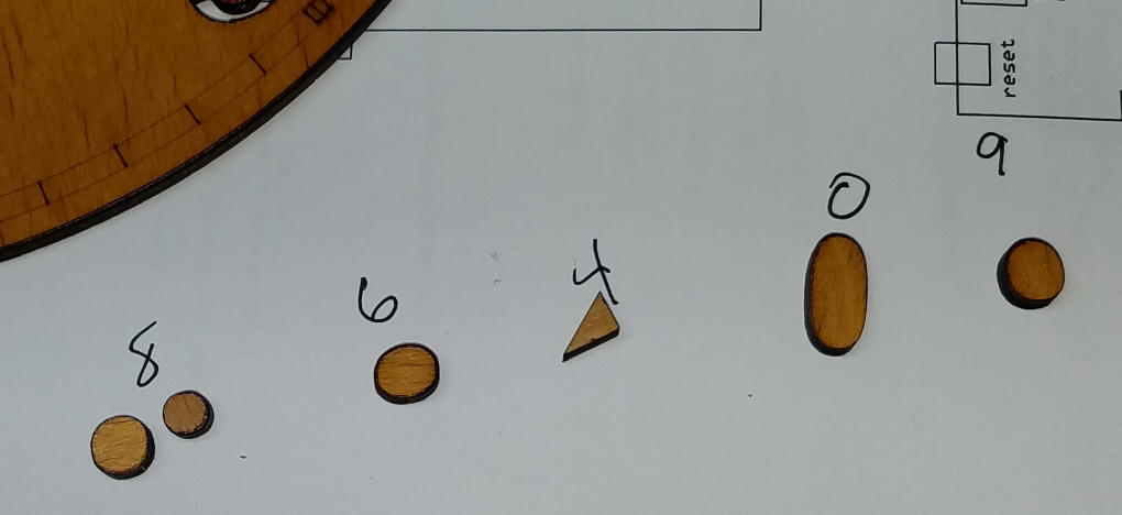
The hands were also cut out with the laser cutter.
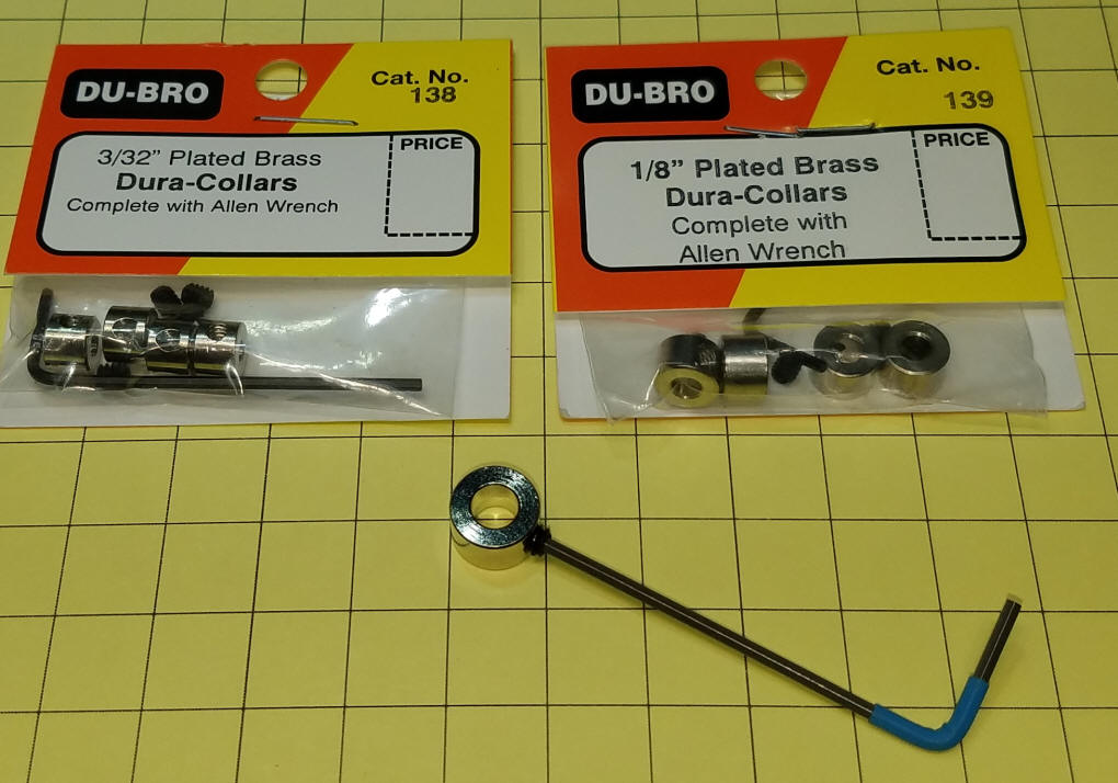
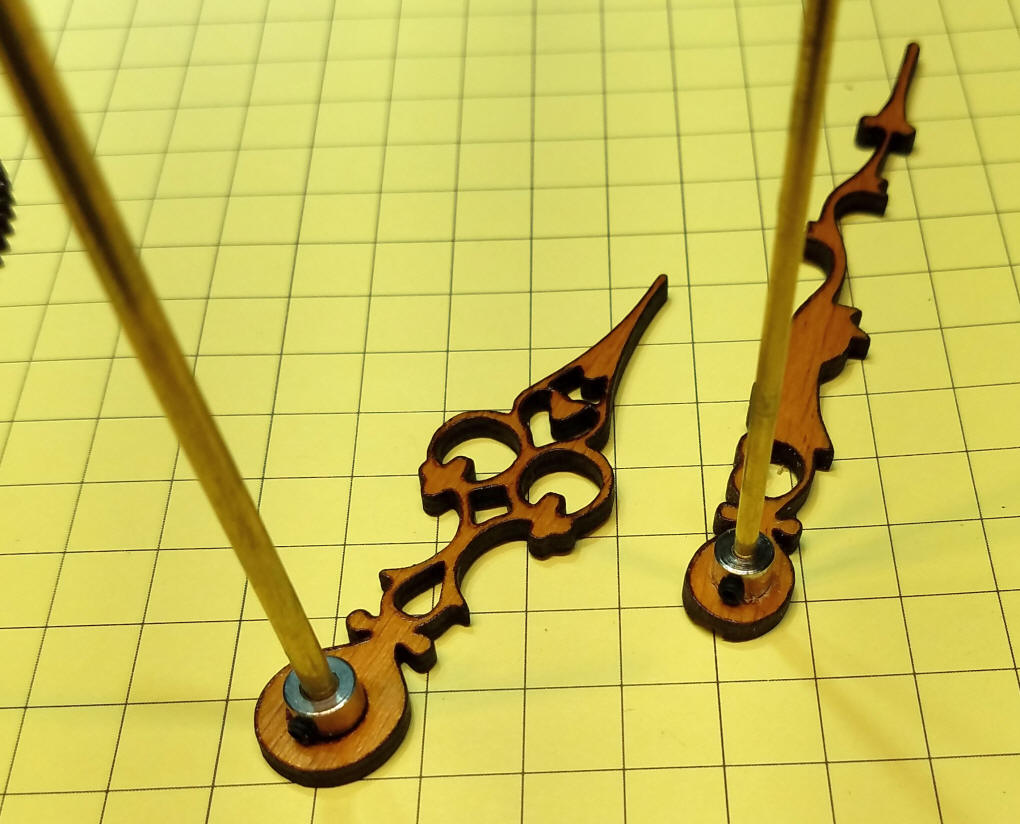
To attach the hands to the brass shafts, small collars with set screws were glued to each hand. These are called DUBRO collars. I used one with a 1/8" hole in the center and one with a 3/32" hole. The larger collar in the photo clearly shows the set screw and hex wrench that comes with the collars.
It is important that the collars be glued to the hands so that the shaft and hands are at 90 degrees to each other. Temporarily inserting a piece of tubing helps with this alignment. I used fast setting epoxy to glue the collars to the hands.
Here is one of the 4 prototypes I built.
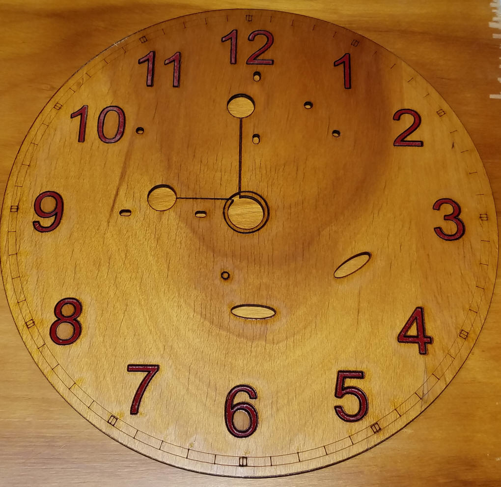
The clock face was also done on the laser cutter. The large
gear at the top was made of acrylic so that the number "12" would
not be obscured. My latest clock face was made by having the laser cutter cut out each numeral so that I could paint them red then reinsert them in the face.
I saved the holes and glued them in after painting.
Once the paint was dry the numerals were reinserted and glued from the back.
|
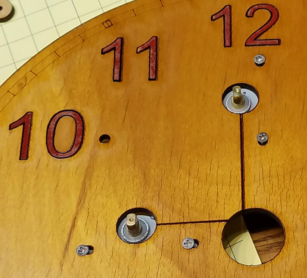
| Mounting the Stepper Motors The stepper motors are attached to the clock face with four 2-56 x 1/2" flat head machine screws & nuts. Note the shape of the shafts on the stepper motors. They allow for a good force-fit of the gears.
The stepper motors extend from the back of the clock face. Note the large hole in the area between the two motors. That allows us to adjust the placement of the central gear shaft so that the gears mesh smoothly.
|
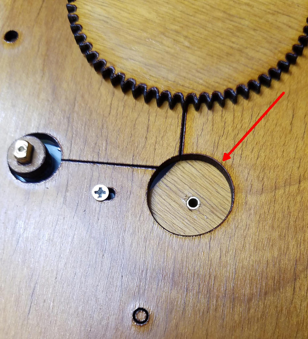
| Mounting Gears & Hands The 64 tooth gears go onto the shafts of the stepper motors. The larger one at the top (so that it partially covers "12") and the smaller to the left. The smaller 64 tooth gear meshes with the upper gear on the central shaft so I used a small wood spacer to raise it a bit. (the spacer is circled in red)
Note that the gear on the left is flush with the top of the stepper motor shaft and the one on the right is down about 1/8".
In order to get a tight fit when inserting the brass shafts I cut the holes in the gears a bit undersized and reamed them out by hand with a 1/8" bit (smaller gear) and a 3/32" bit (larger gear).
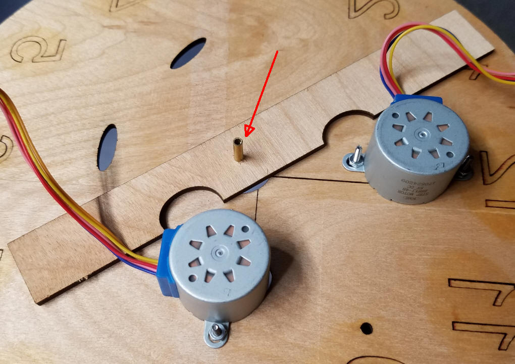
The center brass shaft will go into the small piece of brass shown here & marked with a red arrow.
This piece of brass is attached to a long, rectangular piece of plywood on the back of the clock. The oval cutouts are there to allow clearance of the stepper mounting screws. This piece of wood can be moved about until the two sets of gears mesh with little friction. Once the right placement is found permanently attach this to the back of the clock with small wood screws. Be careful that they don't pierce the front of the clock.
The larger central gear has the 3/32" shaft going through it. The small washer separates the two gears reducing rubbing and excessive friction.
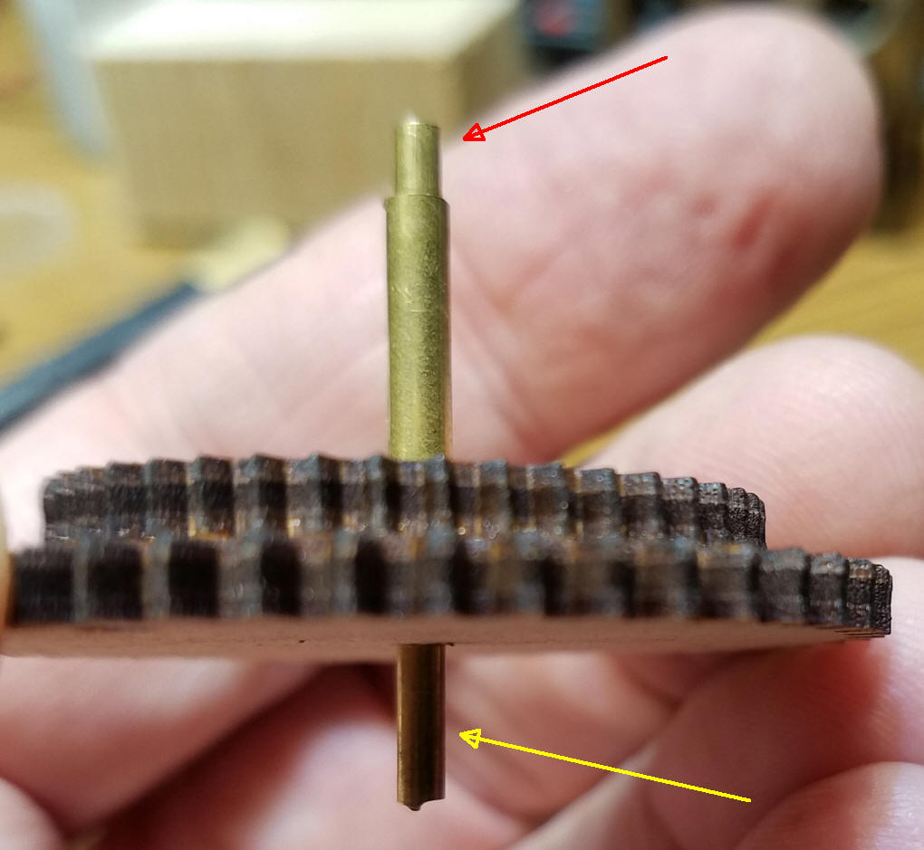
Here the smaller gear, with the 1/8" shaft, is placed over the smaller shaft. Make sure there is minimal rubbing - the two pieces of brass should rotate smoothly. My larger brass shaft is 3/4" long. The smaller shaft is about 1.5" long as it must protrude out of the larger shaft at the top and it must go into the support shaft at the bottom.
The smaller tube can be seen more clearly here along with the way it extends out of the top and bottom of the larger shaft.
|
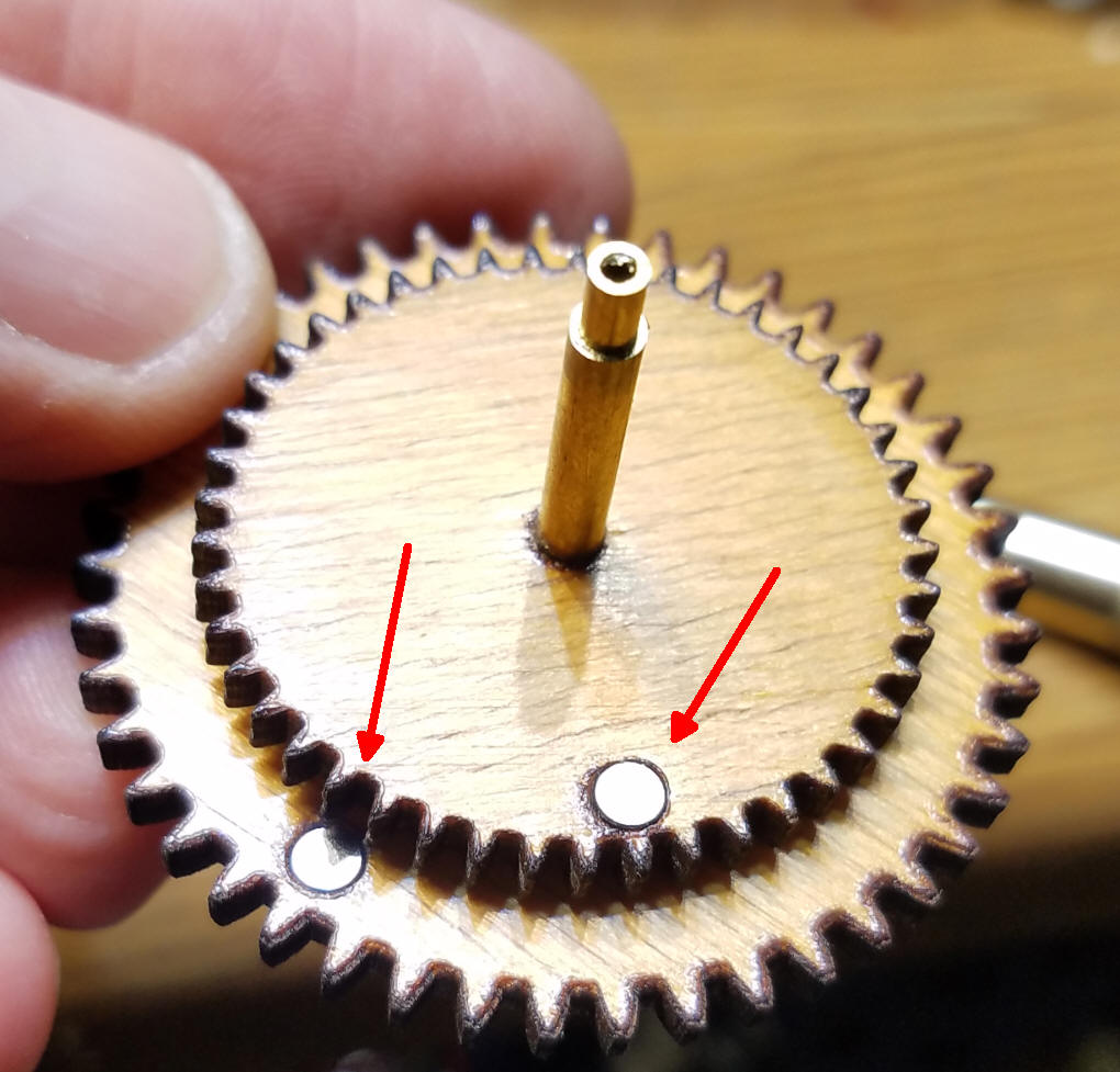
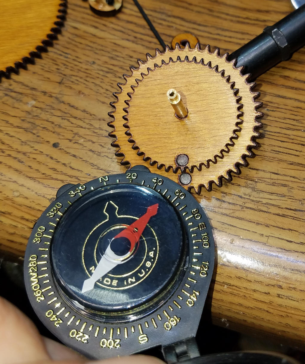
| Magnets & Hall Effect Sensors One of the down sides of using stepper motors for any project is the fact that the controller doesn't know exactly where the motor is on its journey. All you can do is send step commands but if you don't know where the motor started you can't tell where it is at any given time. To overcome that shortcoming a pair of magnets are inserted in small holes in the smaller gears on the central shaft. They are used to stimulate a pair of Hall Effect sensors that can detect a near-by magnetic field. The magnets that I used are 1/8" in diameter and 1/8" thick. Other sizes are sure to work. The important thing is to place them on the gears so that the south pole points up.
You can use a magnetic compass to determine north and south poles. In this photo the arrow points to the south pole.
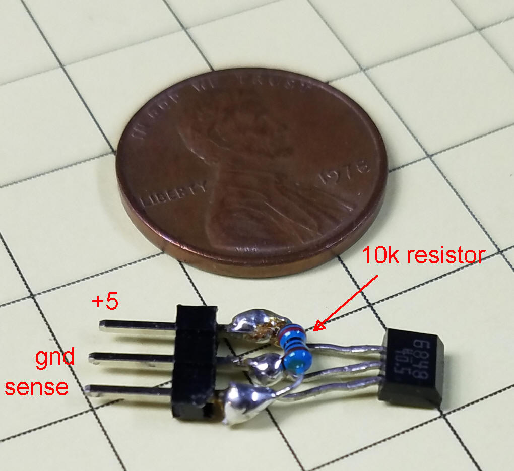
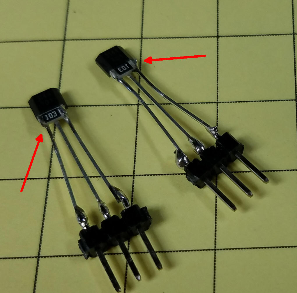
The magnetic sensor, called a Hall Effect Sensor, is shown here. It has three leads, one for +5 volts, one for ground and one that is the output of the sensor. That lead needs to be pulled high with a 10 K resistor. Rather than putting that resistor on the circuit board I generally solder them at the sensor as shown here. The resistor goes between the two outside terminals. The side of the sensor that has a label on it goes towards the magnet with its south pole up. This can also be seen by the shape of the sensor which is tapered on the side with the label.
If you prefer you can use a 10K surface mount resistor as shown in this photo. The connections are still to the outer two leads as the center lead touches the insulated part of the resistor.
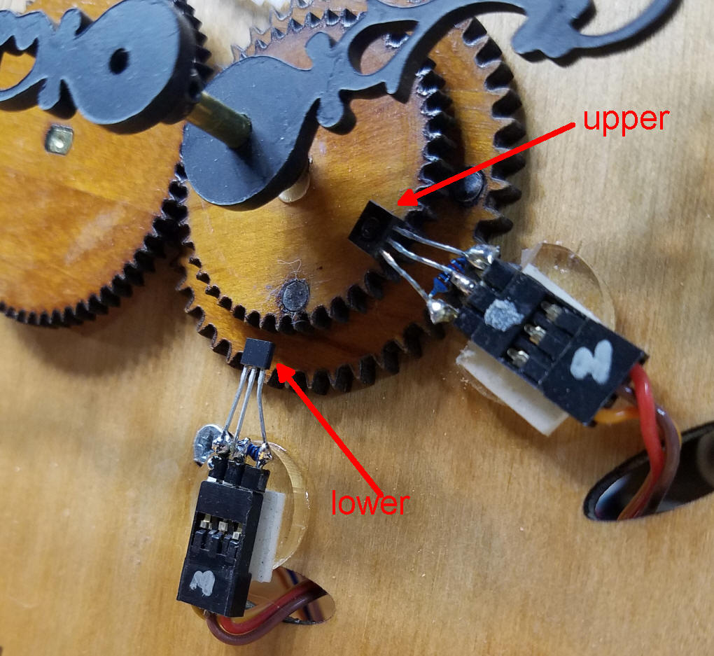
The Hall sensors are placed so that one sits just above where the upper magnet will pass and the other sits just above where the lower magnet will pass. In each case the tapered, label side is facing down towards the magnets. Once I got them in place they were glued to the clock face.
That completes the clock face. There will be a number of wires on the back of the clock. Two pairs of 3 wires from the Hall sensors and two pairs of 5 wires coming from the stepper motors. |
Parts
|
| The Arduino Hardware While it might be possible to get this clock working with just an ESP8266, the board that connects to WiFi to set the clock's time, I found that using both an Arduino Pro Mini and a Wemos D1 gave me more flexibility and more pins to connect to the clock mechanism. The prototype clock circuits were build on circuit board that I designed for another purpose. It did have accommodations for both the Pro Mini and the DFPlayer so very few modifications were needed to adapt it to the clock. |
| Sound for Westminster Chimes Detailed information on the DFPlayer and the MP3 files that are used for the Westminster Chimes is on my web page here: http://www.trainelectronics.com/Arduino/LED_Matrix/Chimes/index.htm This page includes a link to download the MP3 files that I used. |
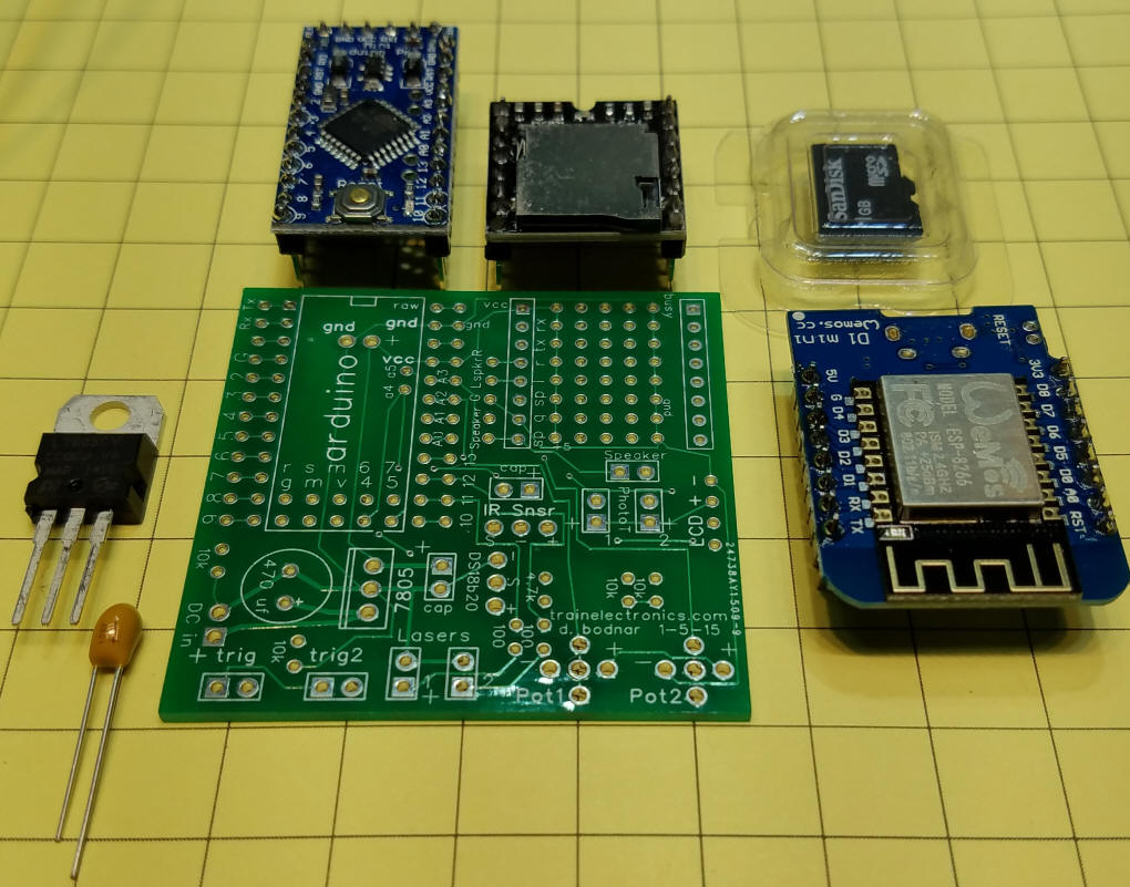
| The main components that are used are
shown in the next two photos. The circuit board needs minor
modifications to work with the clock. Clockwise from the upper
left: Arduino Pro Mini, DFPlayer, 1 GB micro SD card,
Wemos D1, circuit board, 10uf tantalum cap, and a 7805 voltage
regulator.
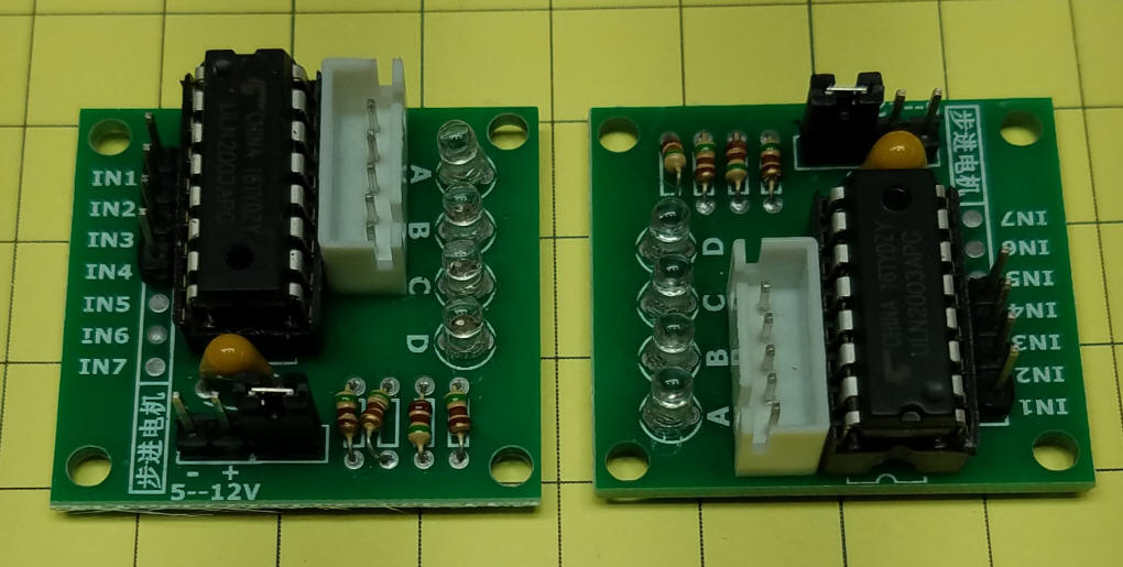
We also need two of the stepper motor driver boards that come with the motors.
|
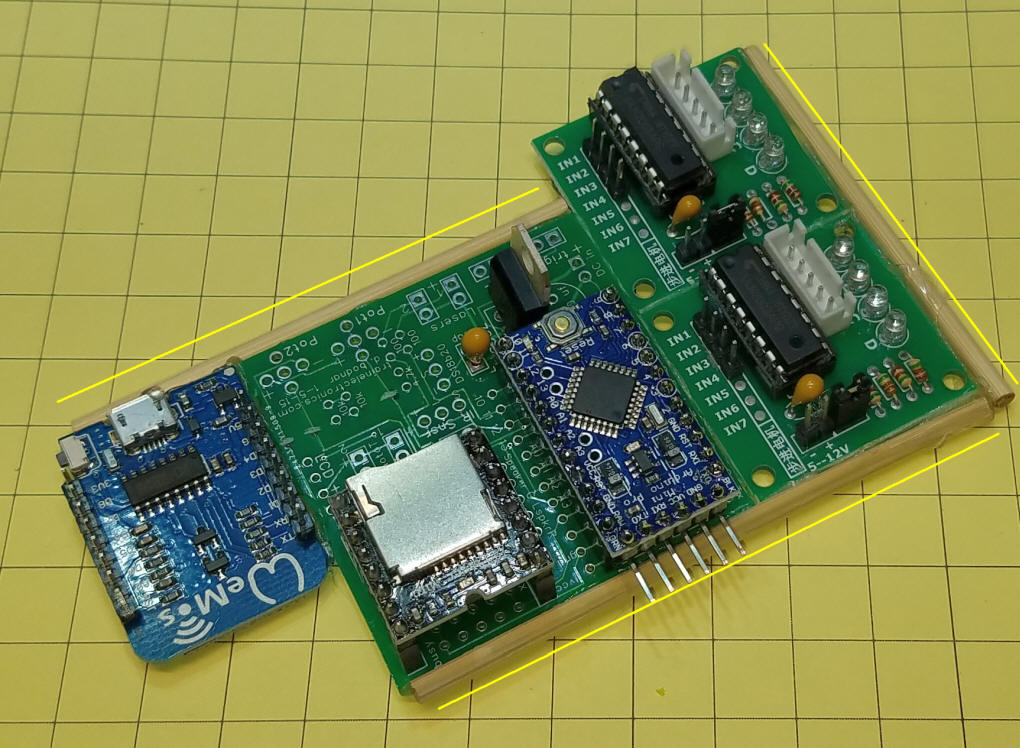
| Combine Boards To simplify wiring and make a more secure circuit I opted to attach all four boards together with hot glue and wooden rods.
|
| Schematic The wiring diagram shows the two stepper motors, the Pro Mini, the DFPlayer, the Wemos D1 and the two Hall Effect sensors and how they are all wired together. Note that the stepper motors work from the same 5 volt power supply that operates the rest of the circuit. This makes things much simpler! If you opt to use 6 or 7 volts for the steppers just be sure to have a common ground to the rest of the circuit.
|
|
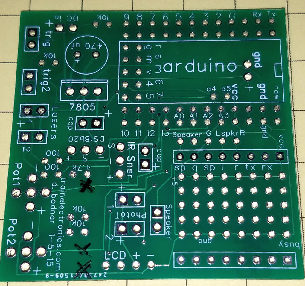
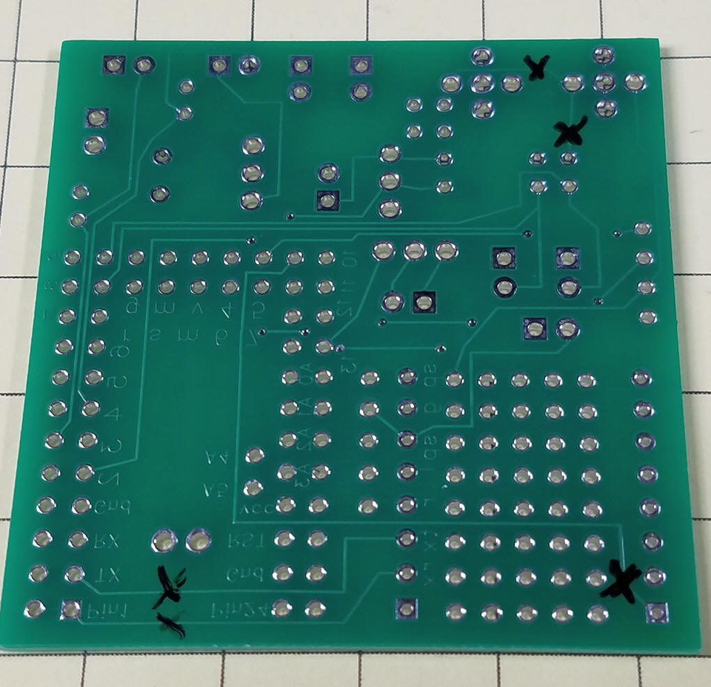
The Electronics I built the main board, that houses the power supply, Pro Mini and DFPlayer using a circuit board that I designed for another project. My notes on using that board are shown here. You could also use a prototyping board and solder wires to connect the various pins on the circuit. The three traces that need to be cut on the top of the board are shown here...
... and the five on the back are here.
|
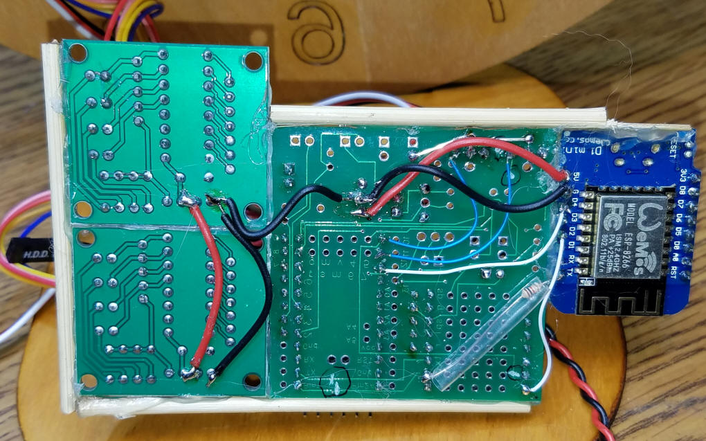
| The wiring on the back is shown here.
The resistor between the TX on the Wemos D1 and the RX on the
DFPlayer is in a piece of clear tubing to insulate it. The
larger sized red & black wires connect +5 and ground from
board-to-board. The thin blue wires go to the Hall sensor pins
and the small white wires go to the DFPlayer and Wemos D1.
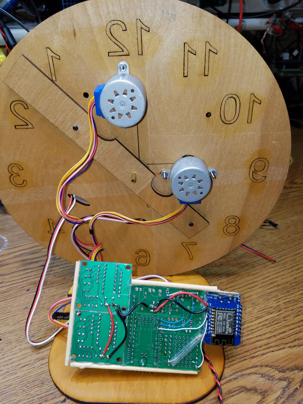
Here is the back of the clock showing the two stepper motors. The diagonal strip of wood is the one that supports the central shaft. The two small black screws secure it to the clock face.
|
| Initial Setup When you first run the program the hands will rotate until each magnet is detected. At this point the hands should both be straight up pointing to 12. If they are not, disconnect the power, loosen the set screws and align them properly. Make sure that you have inserted your WiFi SSID and password into the Wemos program. Once the hands are aligned and the network is identified the clock should set the hands based on the current time. There are a number of Serial print statements in the code that can be used to debug any issues you might have. Just use the IDE's serial monitor to view them - the baud rate needs to be set to 9600. |
| Accuracy The clock is quite accurate due to its getting the time from an Internet time server. The hands do have some backlash, play or "slop" in their movements due to imperfections in the inexpensive stepper motors. You can easily move the hands a minute or two either way. |
| Improvements 1. reset at midnight (or some other hour) 2. restrict chimes to waking hours 3. larger clock face |
| Clock & Gear Files The laser cut parts of the clock were designed in CorelDraw and cut with a generic eBay laser cutter. This laser cutter interfaces directly with CorelDraw. The file I made is here: Arduino/Clock_stepper_hands/images/StepperMotor-9-ratio-change-ALL-V4.cdr
You can print to most laser cutters from a PDF
file, too - a PDF version of the file is here: The gears and hands could also be printed on a 3D printer. The PDF file should help with this. |
| Program - version: Stepper-Dual-RequestTimeTX-SoundOnWemos--v18-0 Download the ZIP file of this sketch here: Arduino/Clock_stepper_hands/Stepper-Dual-RequestTimeTX-SoundOnWemos--v18-0.zip
// d. bodnar 11-18-2017
// changed all to 9600 baud - seems much more stable
// This version is based on 17.3 and does not include DFPlayer code
//  sounds will be taken care of by the Wemos chip

#include <SoftwareSerial.h>
#include <TimeLib.h>
#define TIME_HEADER   'T'   // Header tag for serial time sync message
//#define TIME_REQUEST  7    // ASCII bell character requests a time sync message
int ver = 18;
int verdec = 0;
int totalMins = 0;
int totalHrs = 0;
int startHr = 0;
int startMn = 0;
SoftwareSerial mySerial(12, 13);//  RX  TX   , false, 256);
String readString;
unsigned long epoch = 0;
unsigned long LastEpoch = 0;
String inString = "";
int minCount = 0;
//unsigned long time;
//unsigned long time2;
float moveMinute = 0;
int timeFlag = 0;
int  hr = 0; // hour
int  mn = 0; // minute
int  se = 0; // second
int HourHandEveryOtherFlag = 0;
int MinuteSensorFlag = 0;
int Over59Flag = 0;
int motorPin1 = 2;    // Blue   - 28BYJ48 pin 1
int motorPin2 = 3;    // Pink   - 28BYJ48 pin 2
int motorPin3 = 4;    // Yellow - 28BYJ48 pin 3
int motorPin4 = 5;    // Orange - 28BYJ48 pin 4
int motorPin1b = 6;    // Blue   - 28BYJ48 pin 1
int motorPin2b = 7;    // Pink   - 28BYJ48 pin 2
int motorPin3b = 8;    // Yellow - 28BYJ48 pin 3
int motorPin4b = 9;    // Orange - 28BYJ48 pin 4
int HallSensorOnMinute = 10; // hall sensor - high when magnet detected
int HallSensorOnHour = 11; // smaller gear sensor
//pin 12 used in MySerial
//pin 13 used in MySerial
// not used A0--A7 (A0 to A7 on nano & mini)
//int requestTime = A2; // pull this pin LOW to request serial send of time
int stoppedFlag = 0;
int catchUpFlag = 0;
int newTimeFlag = 0;
int timeOKFlag = 0;
int hourCount = 0;
int minuteCount = 0;
int secondsNow = 0;
int foundMinuteMagnetFlag = 0;
int ticks = 0; // count 10 second periods that have passed
int motorSpeed = 1000;  //variable to set stepper speed
int count = 0;          // count of steps made
int countsperrev = 360; // number of steps per full revolution
int lookup[8] = {B01000, B01100, B00100, B00110, B00010, B00011, B00001, B01001};
int MinuteHallSensor = 0;
int HourHallSensor = 0;
//////////////////////////////////////////////////////////////////////////////
void setup() {
  //declare the motor pins as outputs
  pinMode(motorPin1, OUTPUT);
  pinMode(motorPin2, OUTPUT);
  pinMode(motorPin3, OUTPUT);
  pinMode(motorPin4, OUTPUT);
  pinMode(motorPin1b, OUTPUT);
  pinMode(motorPin2b, OUTPUT);
  pinMode(motorPin3b, OUTPUT);
  pinMode(motorPin4b, OUTPUT);
  // pinMode(requestTime, OUTPUT);

  // pinMode(13, OUTPUT);
  Serial.begin(9600);
  mySerial.begin(9600);
  // setSyncProvider( requestSync);  //set function to call when sync required
  // Serial.println("Waiting for sync message");
  pinMode(HallSensorOnMinute, INPUT);
  pinMode(HallSensorOnHour, INPUT);
  Serial.print("At Setup .... Version ");
  Serial.print (ver);
  Serial.print(".");
  Serial.println(verdec);
  // delay(500);
  // time = millis(); // used for check time on WiFi
  alignHands();  // initial routine to align both hands to noon
  while (epoch == 0) {
    getTime();
  }
  LastEpoch = epoch; // store first reading to compare with new ones
  delay(2000);
  setInitialTime();
  //  time2 = millis(); // used for hand movement
  secondsNow = second();
  totalMins = 0;
  totalHrs = 0;
  startHr = hr;
  startMn = mn;
}

void loop() {
  if (second() - secondsNow == 10 || second() - secondsNow == -50) { // 10 sec = 1 tick of stepper
    secondsNow = second();
    ticks ++;
    MinuteHand();
  }
  //  Serial.print("ticks = ");
  // Serial.println(ticks);
  if (ticks >= 12    ) {   /// changed from == when hour hand stuck or move time forward routine
    Serial.print("ticks = ");
    Serial.println(ticks);
    HourHand();  // move one tick after 12 seconds go by
    ticks = 0;
  }
  if (digitalRead(HallSensorOnMinute) == LOW && foundMinuteMagnetFlag == 0) { // minute hand at 12
    minuteMagnetAt12();
  }
  if (digitalRead(HallSensorOnMinute) == HIGH) {
    foundMinuteMagnetFlag = 0;
  }
}

void minuteMagnetAt12() {
  if (foundMinuteMagnetFlag == 0) {
    timeFlag = 0;
    Serial.println("FOUND MINUTE MAGNET FOUND MINUTE MAGNET");
    getTime();
    timeFlag = 0;
    Serial.print("epoch= ");
    Serial.println(epoch);
    Serial.print("Minute= ");
    Serial.println(mn);
    if (mn >= 1 && mn <= 30) { // 1 to 3 more minutes slow
      Serial.println("Speeding Up A ");
      for (int temp1 = 1; temp1 <=  mn; temp1++) {
        Serial.print(temp1);
        Serial.print(" ");
        Serial.print(" Speeding Up B");
        for (int temp2 = 1; temp2 <= 6  ; temp2++) {
          ticks++;
          MinuteHand();
          Serial.print(temp2);
        }
        Serial.println(" done ");
      }
    }

    if (mn <= 59 && mn >= 31) { // 1 to 3 more minutes fast
      Serial.print("pausing ");
      unsigned long tempTime = (60000 * (60 - mn));
      Serial.println(tempTime);
      Serial.println(millis());
      delay(tempTime); // pause for 1 minute
      Serial.println("done pausing...");
      Serial.println(millis());
    }
    foundMinuteMagnetFlag = 1;
  }
}

void getTime() { // receives a  10 digit # like this: 1506371296
  mySerial.flush();
  mySerial.end();    // Ends the serial communication once all data is received
  mySerial.begin(9600);  // Re-establishes serial communication - clears all buffered info
  Serial.println("Getting time ...");
  while (timeFlag == 0 && timeOKFlag == 0) {
    //    Serial.print("@ timeflag-timeOKflag test ");
    //    Serial.print(timeFlag);
    //    Serial.print("  ");
    //    Serial.println(timeOKFlag);
    if (mySerial.available() > 1) { // wait for at least two characters
      //     Serial.println("Found >1");
      char c = mySerial.read();
      //     Serial.print(" Char c = ");
      //     Serial.println(c);
      if ( c == TIME_HEADER) {   // did we get a 'T' ???
        Serial.println("@ processSyncMessage");
        processSyncMessage();
        timeFlag = 1;
      }
    }
  }
  // Serial.print("Epoch is ");
  // Serial.println(epoch);
  timeFlag = 1;
  hr = ((epoch  % 86400L) / 3600);
  hr = hr - 5; // 4 for daylight savings time in Eastern US - -5 for EST
  if (hr <= 0) hr = hr + 12;
  if (hr > 12) hr = hr - 12;
  Serial.print(hr);
  Serial.print(':');
  if ( ((epoch % 3600) / 60) < 10 ) {
    // In the first 10 minutes of each hour, we'll want a leading '0'
    Serial.print('0');
  }
  mn = ((epoch  % 3600) / 60);
  Serial.print(mn);
  Serial.print(':');
  if ( (epoch % 60) < 10 ) {
    // In the first 10 seconds of each minute, we'll want a leading '0'
    Serial.print('0');
  }
  se = (epoch % 60);
  inString = "";
  timeFlag = 1;
  timeOKFlag = 0;
}

void processSyncMessage() {
  const unsigned long DEFAULT_TIME = 1357041600; // Jan 1 2013 - paul, perhaps we define in time.h?
  epoch = 0;
  // while ( epoch <= (LastEpoch + 3500) || (epoch >= LastEpoch + 3700 ) || newTimeFlag == 0) {
  epoch = mySerial.parseInt();
  Serial.print("new PCTIME= ");
  Serial.print(epoch);
  Serial.println("");
  //  if ( epoch >= (LastEpoch + 3500) && (epoch <= LastEpoch + 3700 )) { // check the integer is a valid time (greater than Jan 1 2013)
  //    setTime(pctime); // Sync Arduino clock to the time received on the serial port
  Serial.println("OK with DEFAULT_TIME");
  timeOKFlag = 1; // set to 1 if time is OK with default time
  LastEpoch = epoch;
  //   }
  //    if (newTimeFlag == 0) {
  //      Serial.println("Got to newtimeflag");
  //      newTimeFlag = 1;
  //      LastEpoch = epoch-(60*60);
  //    }
  // }
}

void setInitialTime() {
  Serial.println("@ setInitialTime");
  Serial.print("Hr Hand Move for ");
  Serial.println(hr);
  for (count = 1; count < hr + 1  ; count++) { // goes from 1 to 12
    for (int temp2 = 1; temp2 <= 30; temp2++) {
      HourHand();
      delay(10);
    }
  }
  Serial.println("");
  Serial.print("min Hand Move for ");
  Serial.println (mn);
  for (count = 1; count < mn + 1  ; count++) { // goes from 1 to 60
    // Serial.println("");
    for (int temp2 = 1; temp2 <= 6; temp2++) {
      MinuteHand();
      delay(10);
    }
  }
  // need to adjust hour hand for proportion that he minute has moved of 60 minutes
  Serial.println(  mn / 2);
  Serial.print("adjusting Hour Hand a bit ");
  for (int temp2 = 1; temp2 <=   mn / 2; temp2++) {
    HourHand();
    delay(10);
    Serial.print(temp2);
    Serial.print(" ");
  }
  Serial.println("");
}

void alignHands() {
  Serial.println("At alignHands");
  MinuteHallSensor = digitalRead(HallSensorOnMinute);
  HourHallSensor = digitalRead(HallSensorOnHour);
  //  int xxx = 0;
  //  do  {
  //    MinuteHallSensor = digitalRead(HallSensorOnMinute);
  //    HourHallSensor = digitalRead(HallSensorOnHour);
  //    Serial.print(MinuteHallSensor);
  //    Serial.print(" ");
  //    Serial.println(HourHallSensor);
  //  }
  //  while (xxx == 0);
  if (MinuteHallSensor == LOW || HourHallSensor == LOW) {
    Serial.println("MOVING BOTH HANDS FROM MAGNETS");
    for (int temp = 0; temp < 50; temp++) {
      Serial.print(temp);
      Serial.print(" ");
      MinuteHand();
      HourHand();
    }
  }
  for (count = 1; count < countsperrev * 2; count++) { // goes from 1 to 360
    if (catchUpFlag == 0) {
      MinuteHand();
      //  Serial.print("Moving Minute Hand ");
    }
    MinuteHallSensor = digitalRead(HallSensorOnMinute);
    HourHallSensor = digitalRead(HallSensorOnHour);
    // Serial.print(MinuteHallSensor);
    //  Serial.print(" ");
    //  Serial.println(HourHallSensor);
    // Flag added so bottom magnet can't weaken upper and show HIGH when it passes
    if (MinuteHallSensor == LOW) MinuteSensorFlag = 1;
    if (MinuteSensorFlag == 1) { // goes low when hit by magnet
      catchUpFlag = 1;
      HourHand();
      // Serial.print("Moving Hour Hand  ");
      HourHallSensor = digitalRead(HallSensorOnHour);
      if (HourHallSensor == LOW) {
        break;
      }
    }
  }
  Serial.println("ALIGNED!!!");
  MinuteSensorFlag = 0;
}

void MinuteHand()
{
  totalMins ++;
  for (int i = 7; i >= 0; i--)
  {
    setMinuteHand(i);
    delayMicroseconds(motorSpeed);
  }
  allLow();
}

void HourHand()
{
  totalHrs ++;
  for (int i = 7; i >= 0; i--)// was 7 now 3
  {
    setHourHand(i);
    delayMicroseconds(motorSpeed);
  }
  allLow();
}

void setMinuteHand(int out)
{
  digitalWrite(motorPin1b, bitRead(lookup[out], 3));
  digitalWrite(motorPin2b, bitRead(lookup[out], 2));
  digitalWrite(motorPin3b, bitRead(lookup[out], 1));
  digitalWrite(motorPin4b, bitRead(lookup[out], 0));
}

void setHourHand(int out)
{
  digitalWrite(motorPin1, bitRead(lookup[out], 3));
  digitalWrite(motorPin2, bitRead(lookup[out], 2));
  digitalWrite(motorPin3, bitRead(lookup[out], 1));
  digitalWrite(motorPin4, bitRead(lookup[out], 0));
}

void allLow()
{
  digitalWrite(motorPin1b, LOW );
  digitalWrite(motorPin2b, LOW );
  digitalWrite(motorPin3b, LOW);
  digitalWrite(motorPin4b, LOW );
  digitalWrite(motorPin1, LOW );
  digitalWrite(motorPin2, LOW );
  digitalWrite(motorPin3, LOW );
  digitalWrite(motorPin4, LOW );
}
|
| Code for WiFi Wemos D1 Version:
Wemos-from-chimes-sendEpoch-v2-0-esp
NOTE: download and unZIP this file to
get all of the parts of the sketch: /// FOUND HERE https://www.youtube.com/watch?v=YUtqLjs-alo
// Thanks John Rogers !
#include "Arduino.h"
#include <ArduinoJson.h>
#include <ESP8266WiFi.h> //ESP8266 Core WiFi Library (you most likely already have this in your sketch)
//#include <WiFi.h>
#include <SoftwareSerial.h>
//SoftwareSerial swSer(14, 12, false, 256);
SoftwareSerial swSer(16, 2); // RX TX (D4) , false, 256);
#include <DFPlayer_Mini_Mp3.h>
WiFiClient client;
int i;
int day, month, year, dayOfWeek;
int summerTime = 0;
String date;
byte flag1 = 0; // quater hour
byte flag2 = 0; // half hour
byte flag3 = 0; // three quarter hour
byte flag4 = 0; // hour
#define NUM_MAX 4
//// pins: D0-16,D1-5,D2-4,D3-0,D4-2,D5-14,D6-12,D7-13,D8-15,RX-3,TX-1 ////
// for NodeMCU 1.0
#define DIN_PIN 13 // D7
#define CS_PIN 0 // D3
#define CLK_PIN 14 // D5
#define buusyPin 4 //d2
#define SerOut 16 //d0
int bsy = 0;
int z = 0;
long epoch = 0;
unsigned long GetTimetime = millis();
unsigned long OneSecondSendtime = millis();
//#include "max7219.h"
//#include "fonts.h"
#define HOSTNAME "ESP8266-OTA-"
int val = 0; // variable to store the value coming from the sensor
// =======================================================================
// CHANGE YOUR CONFIG HERE:
// =======================================================================
const char* ssid = "main2"; // SSID of local network
const char* password = "passpass"; // Password on network
#define CO2_TX D4 //changed from D1 as it crashed with D1
#define CO2_RX D6 // note D6 is not used, just a place holder
// =============================DEFINE VARS==============================
#define MAX_DIGITS 4 // was 20
byte dig[MAX_DIGITS] = {0};
byte digold[MAX_DIGITS] = {0};
byte digtrans[MAX_DIGITS] = {0};
int updCnt = 0;
int dots = 0;
long dotTime = 0;
long clkTime = 0;
int dx = 0;
int dy = 0;
byte del = 0;
int h, m, s;
float utcOffset = -5; // -4=EDT, -5=EST
long localEpoc = 0;
long localMillisAtUpdate = 0;
void setup()
{
Serial.begin(9600);
swSer.begin(9600);
mp3_set_serial (Serial); //set Serial for DFPlayer-mini mp3 module
mp3_reset();
delay (400);
delay (400);
Serial.print("Connecting WiFi ");
WiFi.begin(ssid, password);
while (WiFi.status() != WL_CONNECTED) {
delay(500);
Serial.print(".");
}
Serial.println("");
Serial.print("MyIP: "); Serial.println(WiFi.localIP());
delay(1500);
mp3_play(5); // for testing
dlayPrint();
GetTimetime = millis();
OneSecondSendtime = millis();
getTime();
updateTime();
}
// =======================================================================
void loop() {
if (updCnt <= 0) { // every 10 scrolls, ~450s=7.5m
updCnt = 60;
Serial.println("Getting data ...");
getTime();
Serial.println("Data loaded");
clkTime = millis();
}
if (millis() - clkTime >= 60000 && !del && dots) { // clock for 30s, then scrolls for about 30s
updCnt--;
clkTime = millis();
}
if (millis() - dotTime >= 500) {
dotTime = millis();
dots = !dots;
}
if (millis() - GetTimetime >= 60000) {
updateTime();
GetTimetime = millis();
}
if (millis() - OneSecondSendtime >= 1000) {
updateTime();
// Serial.print("T");
// Serial.println(epoch);
// swSer.println("T");
// swSer.println(epoch);
OneSecondSendtime = millis();
}
if (m == 15 & flag1 == 0) {
Serial.print("h= ");
Serial.print(h);
Serial.println(" found 15");
mp3_play(1);
Serial.println("play 1");
dlayPrint();
flag1 = 1;
flag2 = 0;
flag3 = 0;
flag4 = 0;
}
if (m == 30 & flag2 == 0) {
Serial.print("h= ");
Serial.print(h);
Serial.println(" found 30");
mp3_play(2);
Serial.println("play 2");
dlayPrint();
flag1 = 0;
flag2 = 1;
flag3 = 0;
flag4 = 0;
}
if (m == 45 & flag3 == 0) {
Serial.print("h= ");
Serial.print(h);
Serial.println(" found 45");
mp3_play(3);
Serial.println("play 3");
dlayPrint();
flag1 = 0;
flag2 = 0;
flag3 = 1;
flag4 = 0;
}
if (m == 0 & flag4 == 0) {
Serial.print("h= ");
Serial.print(h);
Serial.println(" found 00");
mp3_play(4);
Serial.println("play 4");
dlayPrint();
flag1 = 0;
flag2 = 0;
flag3 = 0;
flag4 = 1;
if (h >= 2) {
if (h >= 13) {
h = h - 12;
}
if (h == 0) {
h = 12; // at midnight do 12 chimes
}
for (i = 1; i <= h - 1; i++) {
mp3_play(5); // 5 is chime without end tail
Serial.println("play 5");
dlayPrint();
}
}
mp3_play(6); // 6 is chime with long tail sound
Serial.println("play 6");
}
}
// routine to stay here till busy pin goes low once then goes high after speech item completes
void dlayPrint()
{
int bsyflag = 0;
//// Serial.println(" ");
///// Serial.print("busypin ");
for ( z = 0; z <= 1000; z++) {
if (millis() - dotTime > 500) {
dotTime = millis();
dots = !dots;
}
bsy = digitalRead(buusyPin);
///// Serial.print(bsy);
delay(20);
if (bsyflag == 1 && bsy == 1) {
break;
}
if (bsy == 0) {
bsyflag = 1;
}
}
///// Serial.println(" ");
///// Serial.println("done");
}
// =======================================================================
void getTime()
{
WiFiClient client;
if (!client.connect("www.google.com", 80)) {
Serial.println("connection to google failed");
return;
}
client.print(String("GET / HTTP/1.1\r\n") +
String("Host: www.google.com\r\n") +
String("Connection: close\r\n\r\n"));
int repeatCounter = 0;
while (!client.available() && repeatCounter < 10) {
delay(500);
//Serial.println(".");
repeatCounter++;
}
String line;
client.setNoDelay(false);
while (client.connected() && client.available()) {
line = client.readStringUntil('\n');
line.toUpperCase();
if (line.startsWith("DATE: ")) {
date = " " + line.substring(6, 22);
date.toUpperCase();
// decodeDate(date);
h = line.substring(23, 25).toInt();
m = line.substring(26, 28).toInt();
s = line.substring(29, 31).toInt();
summerTime = checkSummerTime();
if (h + utcOffset + summerTime > 23) {
if (++day > 31) {
day = 1;
month++;
}; // needs better patch
if (++dayOfWeek > 7) dayOfWeek = 1;
}
localMillisAtUpdate = millis();
localEpoc = (h * 60 * 60 + m * 60 + s);
}
}
client.stop();
Serial.print("h@getTime= ");
Serial.println(h);
}
// =======================================================================
int checkSummerTime()
{
if (month > 3 && month < 10) return 1;
if (month == 3 && day >= 31 - (((5 * year / 4) + 4) % 7) ) return 1;
if (month == 10 && day < 31 - (((5 * year / 4) + 1) % 7) ) return 1;
return 0;
}
// =======================================================================
void updateTime()
{
long curEpoch = localEpoc + ((millis() - localMillisAtUpdate) / 1000);
epoch = round(curEpoch + 3600 * ( summerTime) + 86400L) % 86400L;
h = ((epoch % 86400L) / 3600) % 24;
m = (epoch % 3600) / 60;
s = epoch % 60;
// epoch=epoch - 5 * 60*60; // move ahead 5 hours for est
// Serial.print("T");
// Serial.println(epoch);
swSer.println("T");
swSer.println(epoch);
// epoch=epoch + 5 * 60*60; // move ahead 5 hours for est
epoch = round(curEpoch + 3600 * (utcOffset + summerTime) + 86400L) % 86400L;
// Serial.print("h@updateTime= ");
//// Hour (h) is in UTC- change to EST & 12 hour
h = h - 5; // change to EST
if (h <= 0) { // if negative or zero add 12
h = h + 12;
}
if (h > 12) { // if over 12 change to 12 hour format
h = h - 12;
}
// Serial.print("Fixed Hour = "); Serial.println(h);
}
// =======================================================================
|