HC-12 Serial Radio
d. bodnar revised 7-29-2016 4-4-2022
| I have been designing and building
projects that include some sort of radio communication for many
years. These range from a radio control system for model
railroads to an automated train speedometer that rides along the
track while it continuously computes speed and transmits that data
back to a base station. While all of these projects worked I was never 100% satisfied with the radio link. Either the range was limited or interference caused some data packets to be lost. I recently came upon another radio system that may take care of the issues I have had in the past. The HC-12, from Banggood.com, and other vendors, is a fully functional radio-serial link. It is not difficult to configure and, once the baud rate and channel are set, operates as though your two devices are connected by a wire! If you have any project that has two devices connected by a serial link you should be able to make the connection wireless by using two of these bi-directional serial radios. And the price is right, about $10 / pair. |
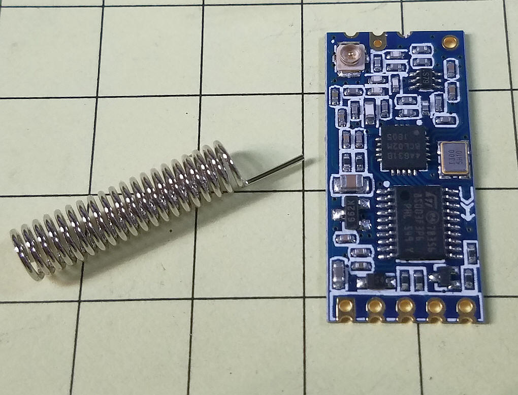
| Initial Setup The unit, as delivered by Banggood, is shown here. A simple coil antenna is to the left and the board itself is next to it. The antenna is not wonderful but may be sufficient for your purposes.
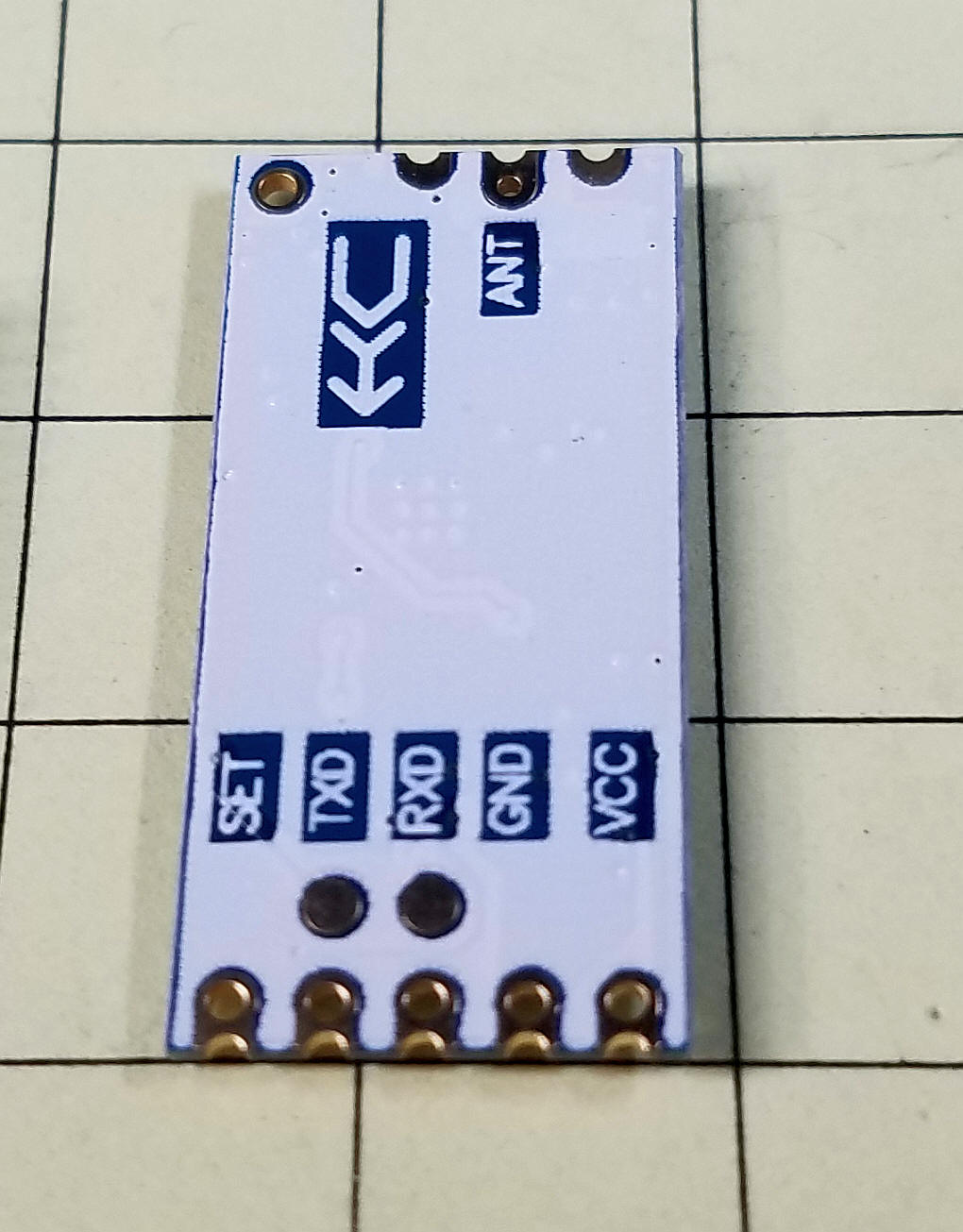
The antenna needs to be soldered to the pad at the top of the board. The five solder pads at the bottom connect to the serial connection on your Arduino or other processor. The connections are clearly labeled on the back of the board.
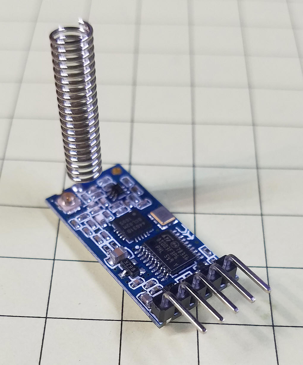
VCC can handle from 3 to 5.5 volts. Set is only used if you need to reconfigure the board. It is pulled high internally and needs to be pulled low by temporarily connecting it to ground to change the configuration. Here I have soldered the antenna to the board and added a 5 pin header (not supplied with the board) to the solder pads on the board.
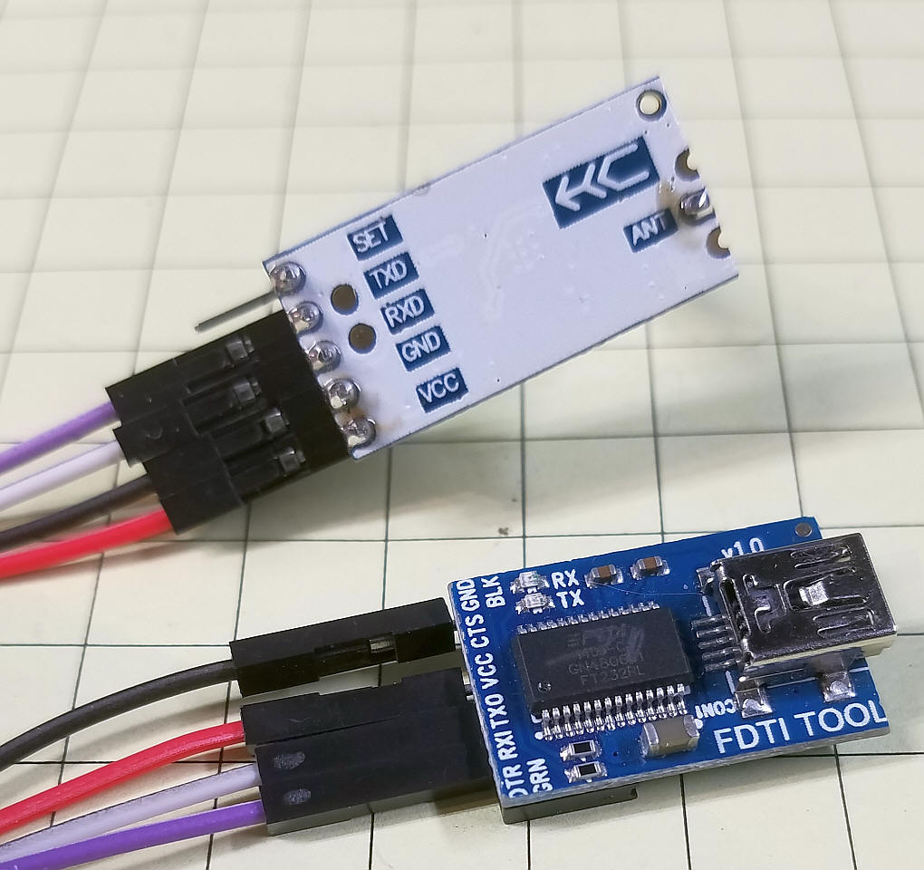
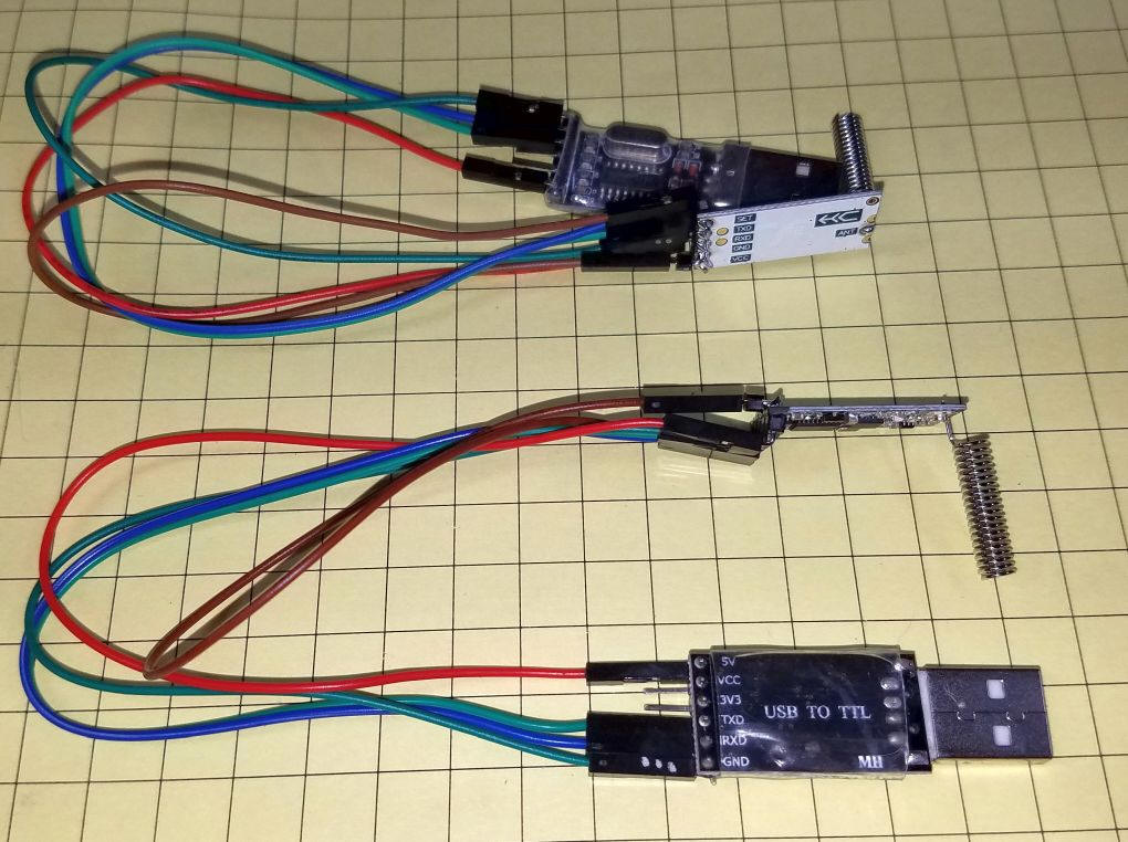
Here the HC-12 board has been connected to a USB to Serial converter for configuration and testing. Note that the TXD on one board connects to RXD on the other board. These converters are readily available and can be purchased from many vendors including:
If your project will work at 9600 baud no configuration is needed as the default settings are:
To change the baud rate, power output and other settings you can use a terminal program and "AT" commands like those that we once used with modems. Information on using these commands is in the manual for the HC-12 which is here: http://trainelectronics.com/Arduino/HC-12-Serial_Radio/images/HC-12%20v2.3A.pdf While the "AT" commands do work, it is much easier to use a simple utility program that can be found here: http://www.thebackshed.com/forum/uploads/robertrozee/2016-01-12_042418_HC12_config.zip Just unzip the program and run the EXE file. More information about the utility can be found here: http://www.thebackshed.com/forum/forum_posts.asp?TID=8246&PN=8 If your project will work at 9600 baud no configuration is needed as the default settings are:
If you want to change any or all of these parameters you must connect the HC-12 to your computer. This can be done with an Arduino Uno or with a USB to Serial converter.
|
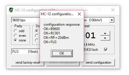
| Using the HC-12 Configuration Tool Place a temporary jumper between the "SET" pin on the HC-12 and the ground pin. This will put the unit into its configuration mode. Connect your USB to Serial Adapter to your computer and note the COM port that it attaches to. This can be checked using Device Manager. On most versions of Windows Device Manager can be reached by clicking the Windows Key and running C:\Windows\System32\en-US\devmgmt.msc When you start the HC-12 Configuration Utility it will ask you to select the COM port that it is connected to. Once that is done the program starts - click "Check Configuration" and you should see a display like this that shows the baud rate, frequency, power and operation mode.
The default baud rate is 9600. For use with DCC++ this needs to be 115200 baud. If you are working in a confined space you can change the power to a lower setting as the default is full power (100 mw). Eight levels of power can be set.
The default frequency is 433.4 MHz. There are 100 channels, each 400 KHz higher than the one before it. The highest frequency is 473.0 MHz. In the US the 433 MHz band is normally reserved for licensed amateur radio operators. There is an exception made for very low power devices which the HC-12 is so long as the power is set to less than 10mw. More information is here: http://predictabledesigns.com/most-important-decision-when-creating-wireless-product/ and here: https://en.wikipedia.org/wiki/LPD433 Due to the extremely low power of the HC-12, even at its highest level, I seriously doubt that their use in a hobbyist environment will ever cause interference to other users. That said, I highly recommend that you read the specific limitations for your country and always keep the power set to the lowest level that serves your needs. This practice will not only limit interference but it will also increase battery life in a battery operated system. Four modes are supported, FU1--FU4. Each mode has specific characteristics that are described in the manual. For most purposes FU3, the default mode, appears to be the best choice. |
|
Testing Software for the Arduino I wrote two simple programs to test the HC-12 units. The first program sends a series of sequential numbers pausing 1 second between transmissions. The sequence can be monitored on the Arduino's terminal screen. |
unsigned long x = 0;
void setup() {
  Serial.begin(115200);
  Serial.println(("HC-12 Ratio Test"));
  delay (200);
  Serial.println(("Sends sequential numbers "));
}

void loop() {
  x++;
  Serial.print("number = ");
  Serial.println(x);
  delay(1000);
} |
|
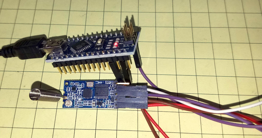
The transmit test unit uses only an Arduino
Pro Micro and the HC-12.
|
|
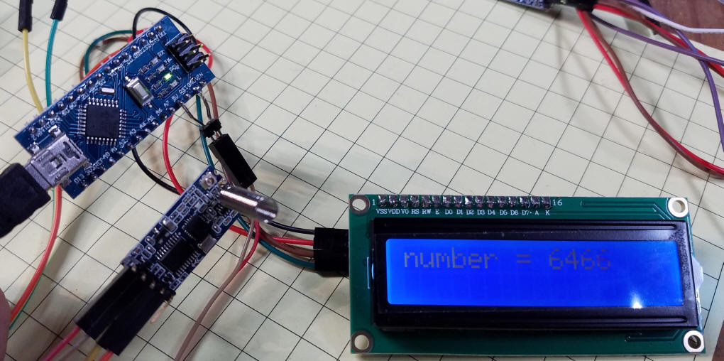
The second program is a bit more complex as it
adds an I2C LCD screen to display what the receiver detects. The addition of the LCD allows you to carry the Arduino, HC-12 and display around to test range and reliability in different places. |
/*
  HC-12 receive test to LCD
  d. bodnar  revised 6-02-2016
*/

int LED = 13; // LED to blink when DCC packets are sent in loop
#include <Wire.h>
#include <LCD.h>
#include <LiquidCrystal_I2C.h>
#define I2C_ADDR    0x27 // <<----- Add your address here.  Find it from I2C Scanner
#define BACKLIGHT_PIN     3
#define En_pin  2
#define Rw_pin  1
#define Rs_pin  0
#define D4_pin  4
#define D5_pin  5
#define D6_pin  6
#define D7_pin  7
LiquidCrystal_I2C	lcd(I2C_ADDR, En_pin, Rw_pin, Rs_pin, D4_pin, D5_pin, D6_pin, D7_pin);

void setup() {
  lcd.begin (16, 2); //  LCD is 16 characters x 2 lines
  lcd.setBacklightPin(BACKLIGHT_PIN, POSITIVE);
  lcd.setBacklight(HIGH);  // Switch on the backlight
  lcd.home (); // go home
  Serial.begin (115200);
  lcd.setCursor(0, 0);
  lcd.print("HC-12 Test");
  lcd.setCursor(0, 1);
  lcd.print("6-02-16  ");
  Serial.print("6-03-2016  version ");
  delay(500);
  lcd.clear();

}  // END SETUP

void loop() {
  lcd.setBacklight(2);  // Switch on the backlight
  char TestData;
  if (Serial.available() )
  {
    TestData = Serial.read();
    if (TestData == 110) { // = 'n'
      lcd.clear();
    }
    Serial.print(TestData);
    if (TestData >= 20) {  // remove cr / lf
      lcd.print (TestData);  // echo the incoming character to the LCD
    }
  }
}  //END LOOP
|
| The receiver adds an LCD display to the
unit.
|
| Range and Reliability When set to low power and 115,200 baud I was able to reliably detect transmissions when the transmitter was in my basement (below grade and behind concrete block and stone walls) and the receiver was at the end of my driveway about 50 yards away. When I upped the transmitter's power to maximum the range increased to well over 100 yards with the transmitter in the same place. I was also able to pick up transmissions in virtually every corner of my home (two story) when the transmitter was at maximum and located in the basement. I also tested low power outside and, at low power, got reliable communication up to about 100 yards. This was not line-of-sight as there were buildings in between. |
| Conclusion While additional tests are needed I believe that the HC-12 is an easy to use and configure wireless serial connection that I will use in many projects. Recommended! |
| Here is another USB-Serial converter that
I got from DXSoul -
http://www.dxsoul.com/product/usb-to-ttl-ch340g-converter-module-adapter-for-arduino-and-stc-901418846 Here are two of them connected to the HC-12 for testing
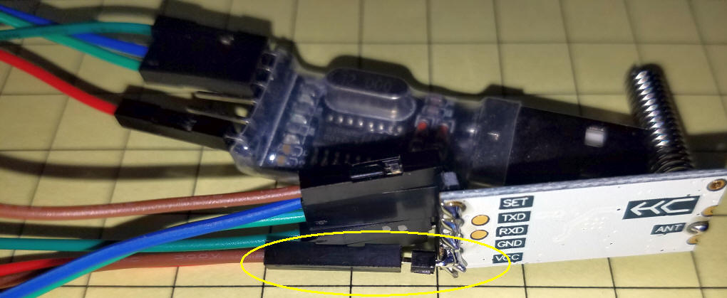
A second pin was added to the GND pin to simplify setting the HC-12 for configuration when connected to SET.
|