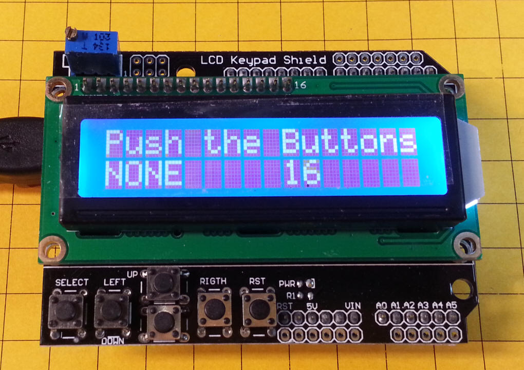
| LCD Keypad Shield My first test was with a readily available 2 line LCD display with a 6 button keypad. I purchased it from BangGood.com - item # SKU083549
I downloaded the Arduino software and used the software I found here to get the board working - easy!
|
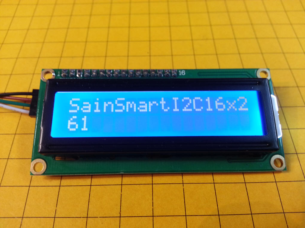
| The next project was with another LCD board,
this one uses an I2C interface. I purchased it from
Deal Extreme
-
item number 173588
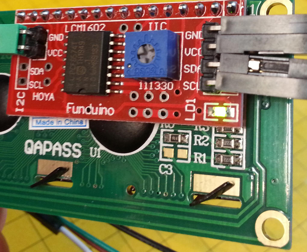
This view of the back of the unit shows the four connection pins, Ground, VCC (+ 5), SDA and SCL.
These pins connect to the Uno board as follows:
The software is here: |
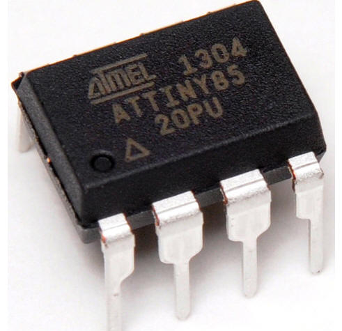
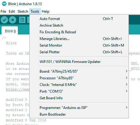
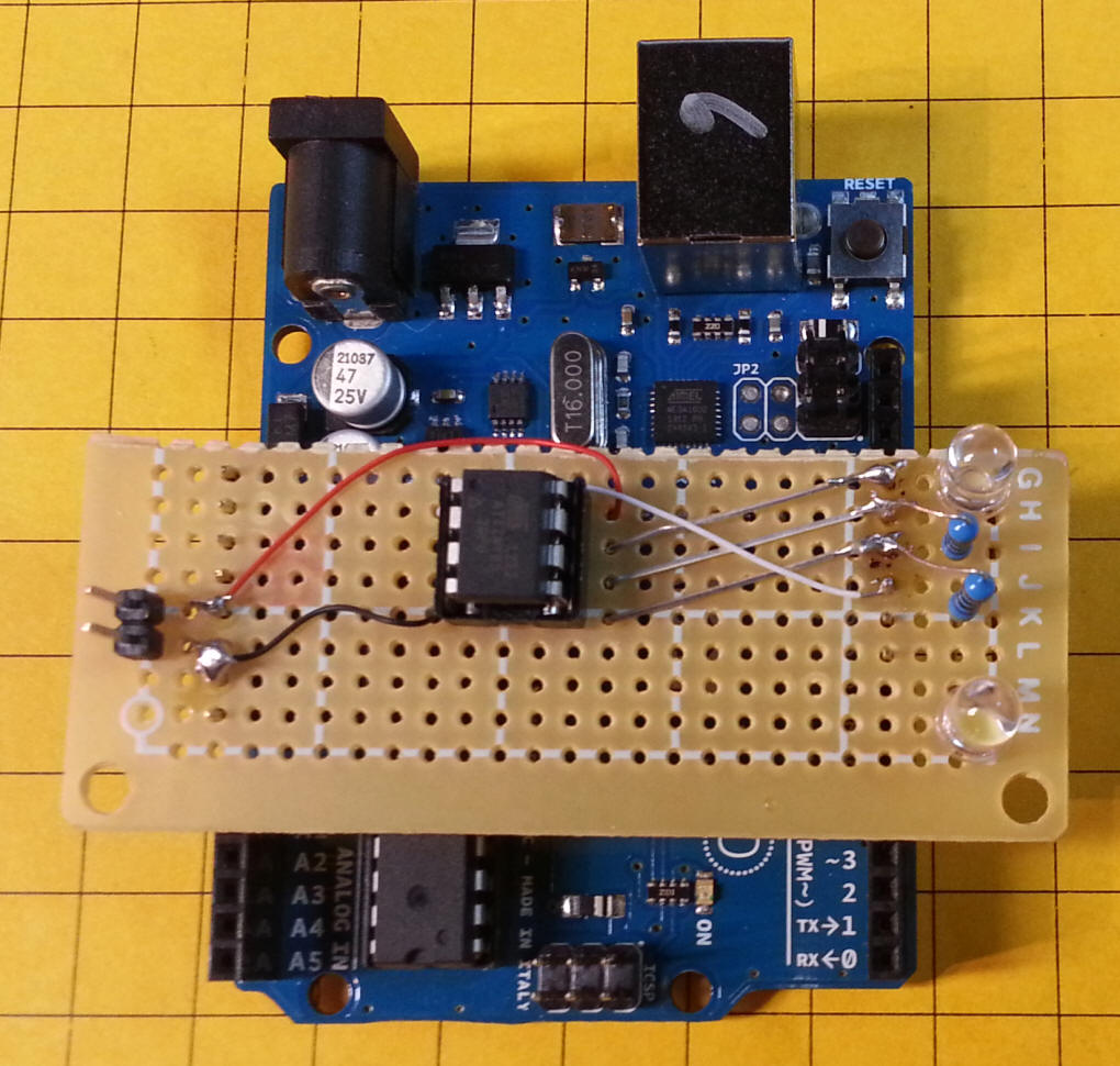
| ATTiny85
The simplest way that I found to program it was to use the Uno board as a programmer. Notes to make it happen are here: http://highlowtech.org/?p=1695 You have to install a program on the Uno chip to turn it into a programmer then connect the ATTiny85 and set the board (under tools) to the ATTiny85. The program is under Examples/ArduinoISP - Note that you have to burn the bootloader to get the chip to 8mhz otherwise it defaults to 1mhz. Rather than use jumper wires to connect the ATTiny to the Uno I made up a simple plug-in to hole the chip and connect to the proper pins. The ATTiny connects to two LEDs that were used to create a pair of ditch lights. The pins at the far left are for an external source of 5 volts for stand alone operation once programmed.
This setup works (10-29-2020) --- use "0" for LED high or low on physical pin 5
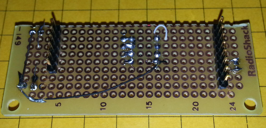
The back of the board.
The software for the ditch light test is based on the "fade" program in the example folder - my modification is here: /* |
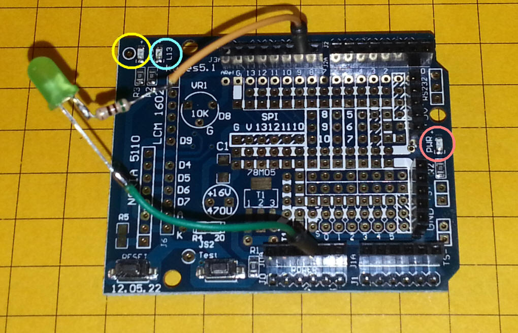
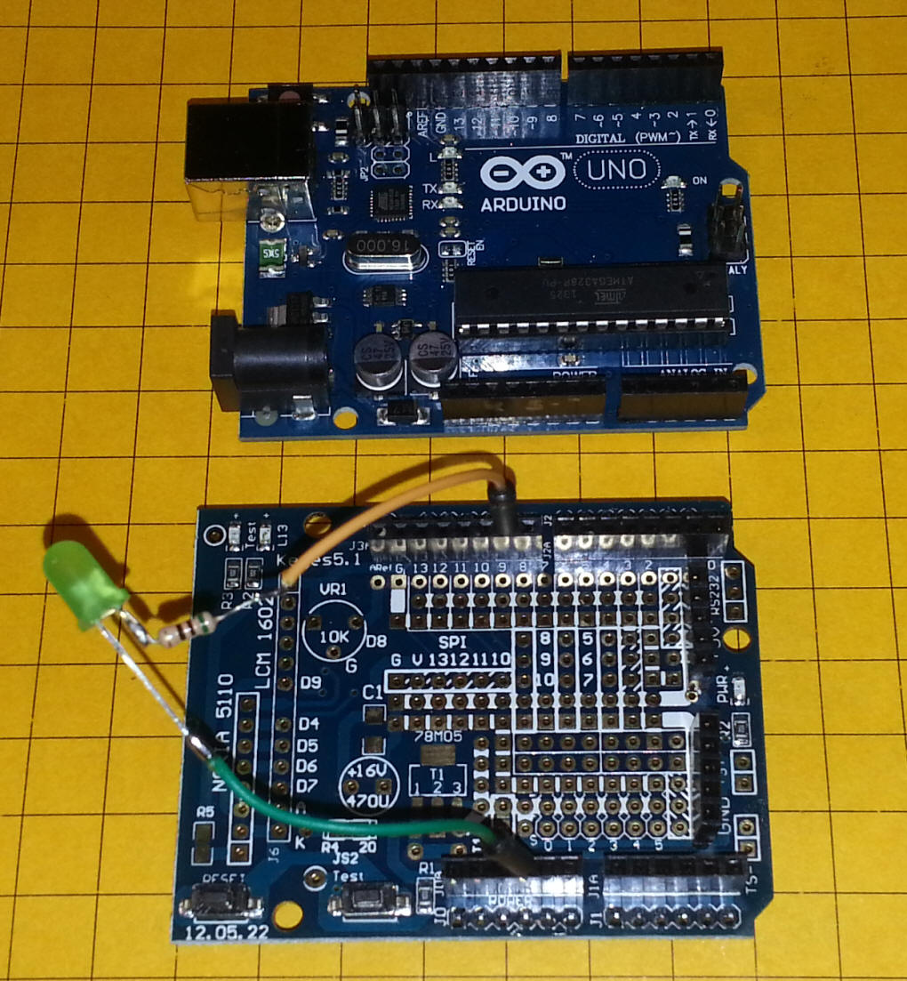
| Add-on Board I ordered the board below from BangGood.com - part # SKU027705 - it is an empty shield that is good for prototyping. Three LEDs are included along with two switches. The POWER LED is circled in pink and an LED that is connected to pin 13 is circled in light blue and labeled L13. The LED to its left (circled in yellow) is labeled TEST - there is a single hole next to it - that is a connection to the anode of the LED - you can put a jumper between that hole and any output pin to use the LED. Both of these LEDs have current limiting resistors in series with them. The button labeled TEST is also wired to a single pin. The switch is pulled high with a pull-up resistor - the test point will go low when the button is pressed. The test point can be connected to any input pin.
|
| Motor Control This project is an exercise in hardware and software to control a motor that could be used to develop a track-powered point-to-point trolley line. It has the following goals:
|
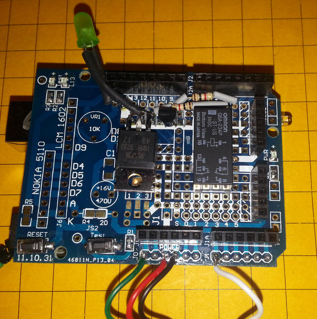
| I used an inexpensive prototyping board to
hold the Mosfet and relay - it is shown below with the Uno. These
are avilable from a number of vendors - I got mine from
BangGood.com for about
$4.00 each.
The board has only a few components, including a reset switch, test switch and three LEDs. Its primary failing is that its two female headers do not line up so that you can add another shield above it. Fortunately this did not pose a problem with this project, as you will see.
|
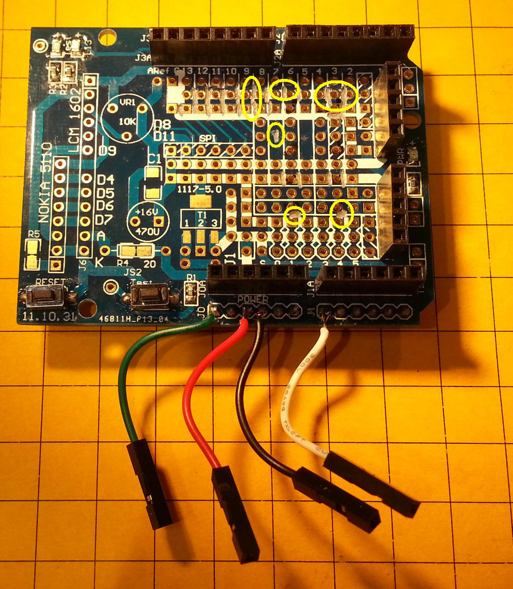
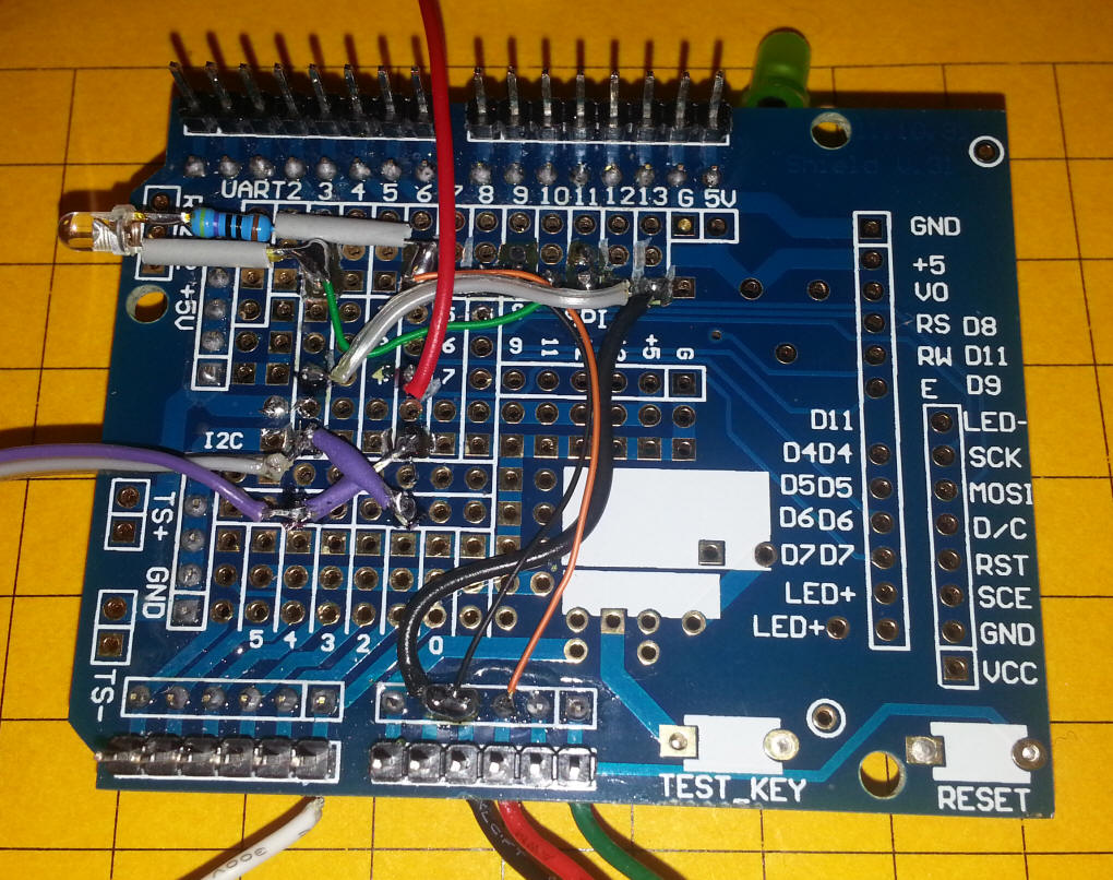
| The LCD that I used is
the one described
above. As you can see I added
four jumpers to supply power to the LCD since it doesn't plug directly
into the 2nd header section. If you look carefully you can see
some of the traces that I had to cut (using a fine bit in a Dremel) to
isolate the leads for the relay and other components.
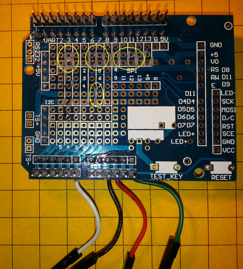
Here you can see some of the traces that were cut on the back.
I used a meter to test each hole that I tried to isolate so that none of the surrounding holes were attached to it. |
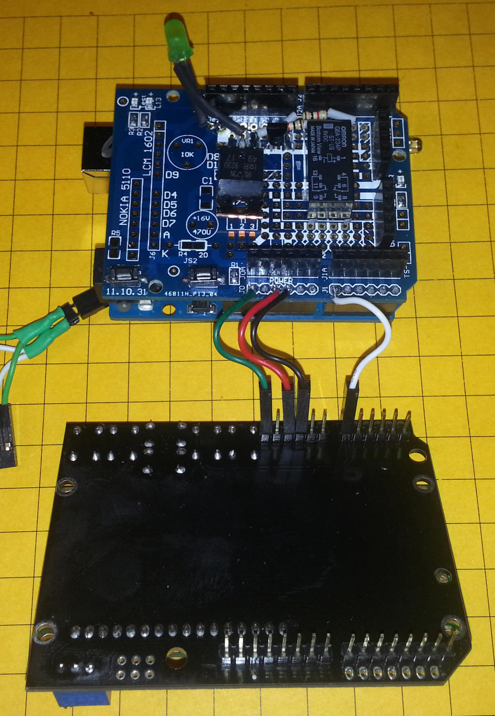
| The prototype board is shown with the relay,
IRL520, a 2N2222 transistor to power the relay and two 1K resistors.
The green LED shows the PWM status.
This close-up shows things a bit more clearly.
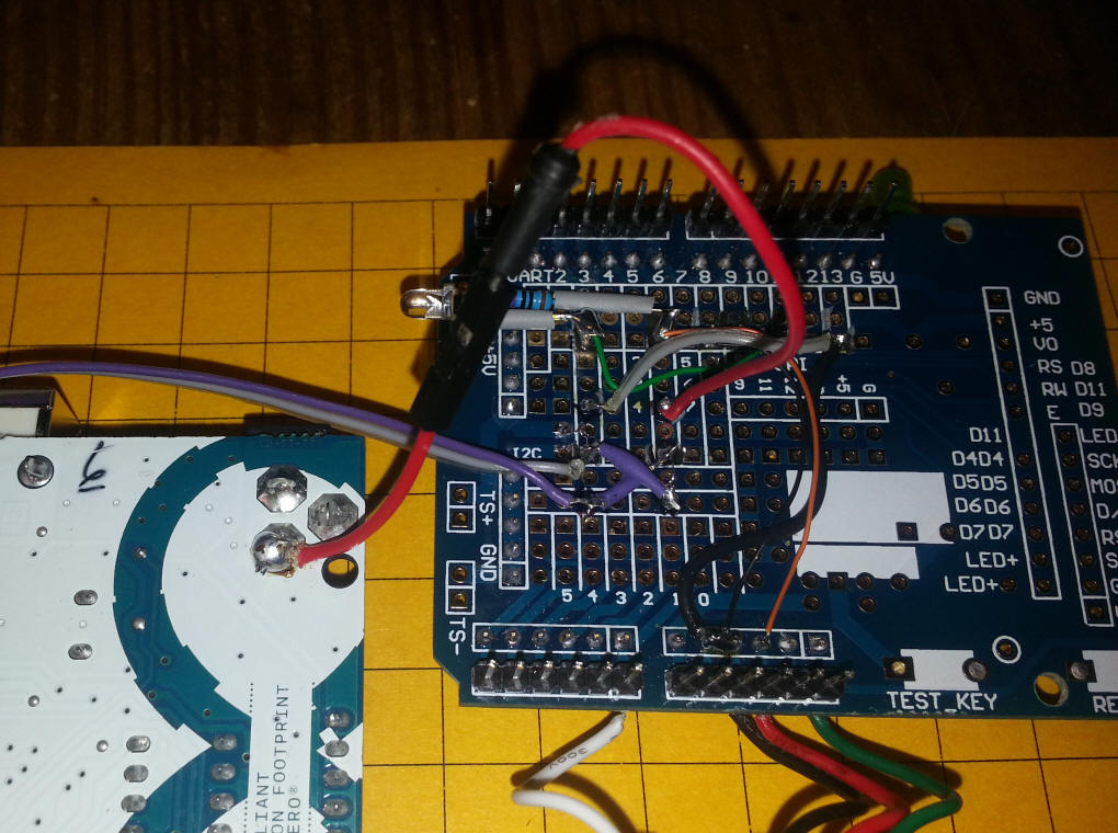
The bottom of the board is rather busy. Note the "X" that crosses the terminals on the DPDT relay so that it reverses the motor. The LED at far left lights when the relay is active. The red wire that goes off of the top of the photo goes to the power input plug on the Uno.
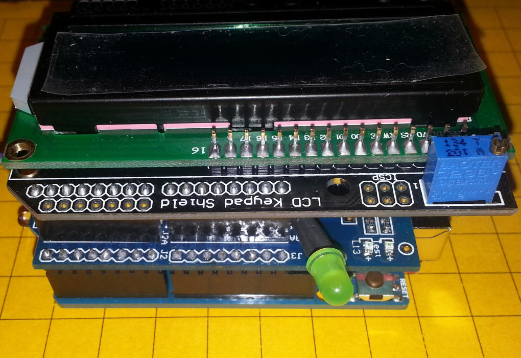
The next few photos show the 3 board stack.
The four connections that go to the LCD board are shown here - they are necessary as the headers on the prototype board don't line up properly.
|
| Software The Arduino code is shown here - it is not meant to be an example of good programming but it works! Notes:
//Sample using LiquidCrystal library
#include <LiquidCrystal.h>


// select the pins used on the LCD panel
LiquidCrystal lcd(8, 9, 4, 5, 6, 7);

// define some values used by the panel and buttons
int lcd_key     = 0;
int adc_key_in  = 0;
#define btnRIGHT  0
#define btnUP     1
#define btnDOWN   2
#define btnLEFT   3
#define btnSELECT 4
#define btnNONE   5
int relay = 2;
int motor = 3;           // the pin that the Motor Mosfet is attached to
int MotorSpeed = 1;    // how bright the LED is
int MotorRate = 8;    // how many points to fade the LED by
int RelayState = 0;  // relay starts off (0)
// read the buttons
int read_LCD_buttons()
{
 adc_key_in = analogRead(0);      // read the value from the sensor
 // my buttons when read are centered at these valies: 0, 144, 329, 504, 741
 // we add approx 50 to those values and check to see if we are close
 if (adc_key_in > 1000) return btnNONE; // We make this the 1st option for speed reasons since it will be the most likely result
 // For V1.1 us this threshold
 if (adc_key_in < 50)   return btnRIGHT;
 if (adc_key_in < 250)  return btnUP;
 if (adc_key_in < 450)  return btnDOWN;
 if (adc_key_in < 650)  return btnLEFT;
 if (adc_key_in < 850)  return btnSELECT;
 return btnNONE;  // when all others fail, return this...
}

void setup()
{
 lcd.begin(16, 2);              // start the library
 lcd.setCursor(0,0);
 lcd.print("Motor Speed Ctrl"); // print a simple message
  pinMode(relay, OUTPUT);
  Serial.begin(9600);
  delay (2000);
  lcd.setCursor(0,0);
  lcd.print("                "); // clear line 1

  }

void decelerate(int MotorSpeed)
 {
   Serial.print("@decel ");
   Serial.println(MotorSpeed);
    lcd.setCursor(0,1);
    lcd.print("     Decel");
   int x=MotorSpeed;
  for ( x=MotorSpeed; x>10;  x--)
  {
  analogWrite(motor, x);
  Serial.println(x);
  delay (10);
  }
 }

void accelerate(int MotorSpeed)
 {
   Serial.print("@accel");
    lcd.setCursor(0,1);
    lcd.print("     Accel");
    int x=MotorSpeed;
   Serial.println(MotorSpeed);
  for (int i=0;i<=MotorSpeed ;i++)
  {
  analogWrite(motor, i);
  Serial.print("@accel ");
  Serial.println(i);
  delay(10);
  }
 }


void loop()
{
    // set the Motor Speed on pin 3:
 analogWrite(motor, MotorSpeed);
if (MotorSpeed ==0) {
  MotorSpeed =1;
}
if (MotorSpeed ==255) {
  MotorSpeed =254;
}
 lcd.setCursor(0,0);
 lcd.print("Motor Speed=");
 lcd.print(MotorSpeed);
 ////lcd.setCursor(11,1);            // move cursor to second line "1" and 9 spaces over
 //lcd.print(millis()/1000);      // display seconds elapsed since power-up
 ////lcd.print(MotorSpeed);
 ////lcd.print(" ");
 lcd.setCursor(0,1);            // move to the begining of the second line
 lcd_key = read_LCD_buttons();  // read the buttons

 switch (lcd_key)               // depending on which button was pushed, we perform an action
 {
   case btnRIGHT:
     {
     lcd.print("RIGHT ");
     lcd.setCursor(13,1); // cursor at end of 2nd line
     lcd.print(">>>");
     if (RelayState==0){
       decelerate(MotorSpeed);
       digitalWrite(relay, HIGH);
       RelayState=1;
       accelerate(MotorSpeed);
     }
     break;
     }
   case btnLEFT:
     {
     lcd.print("LEFT  ");
     lcd.setCursor(13,1); // cursor at end of 2nd line
     lcd.print("<<<");
     if (RelayState==1) {
       decelerate(MotorSpeed);
       digitalWrite(relay, LOW);
       RelayState = 0;
       accelerate(MotorSpeed);
     }
       break;
     }
   case btnUP:
     {
     lcd.print("UP         ");
     MotorSpeed = MotorSpeed + MotorRate;
     MotorSpeed = constrain(MotorSpeed, 0, 255);
     delay(100);
     break;
     }
   case btnDOWN:
     {
     lcd.print("DOWN       ");
     MotorSpeed = MotorSpeed - MotorRate;
     MotorSpeed = constrain(MotorSpeed, 0, 255);
     delay(100);
     break;
     }
   case btnSELECT:
     {
     lcd.print("SELECT");
     break;
     }
     case btnNONE:
     {
     lcd.print("Press Key ");
     break;
     }

 }


}
|
 |