3D Printed Gizmo / Flash
Camera Animation
for Pittsburgh's Children's Hospital
revised 7-13-13
Click Here for Video #1
Click Here for Video #2
(when installed at CHP)
Introduction
I recently purchased a 3D printer (Afinia
H Series) and have been designing my own things and downloading
others from
Thingiverse.com. One of the coolest
things that I found on Thingiverse is a
Motorized
Marble Machine. Not only is it a
great project to test out a 3D printer but it is also great fun to build and
run. The large gear transports metal balls to the top of the gizmo and
delivers them to decreasing radius spiral that returns them to the bottom of the
gear.
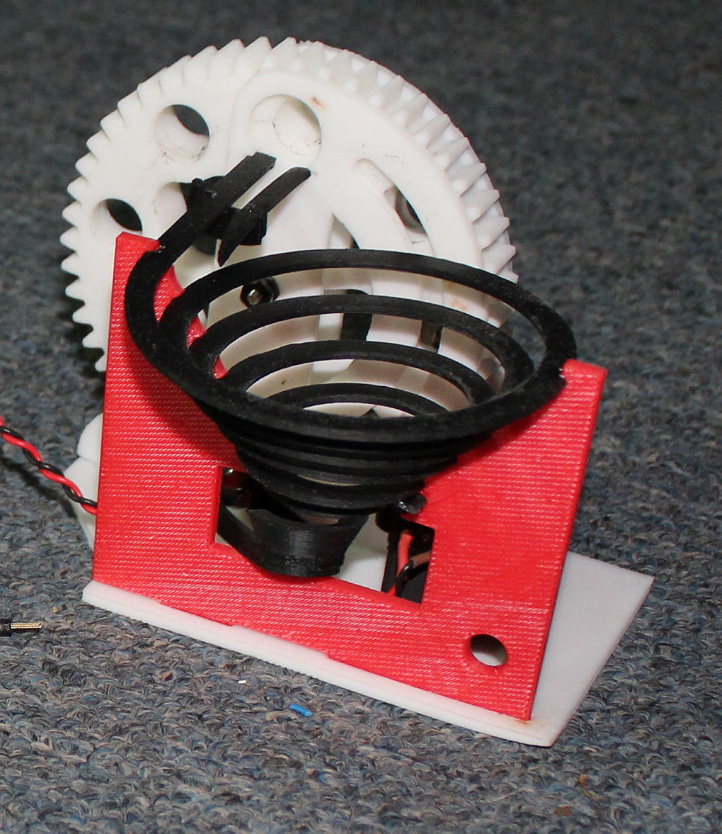
The unit is made up of 11 individual printed parts plus the ball bearings, a motor and a bolt & two nuts.
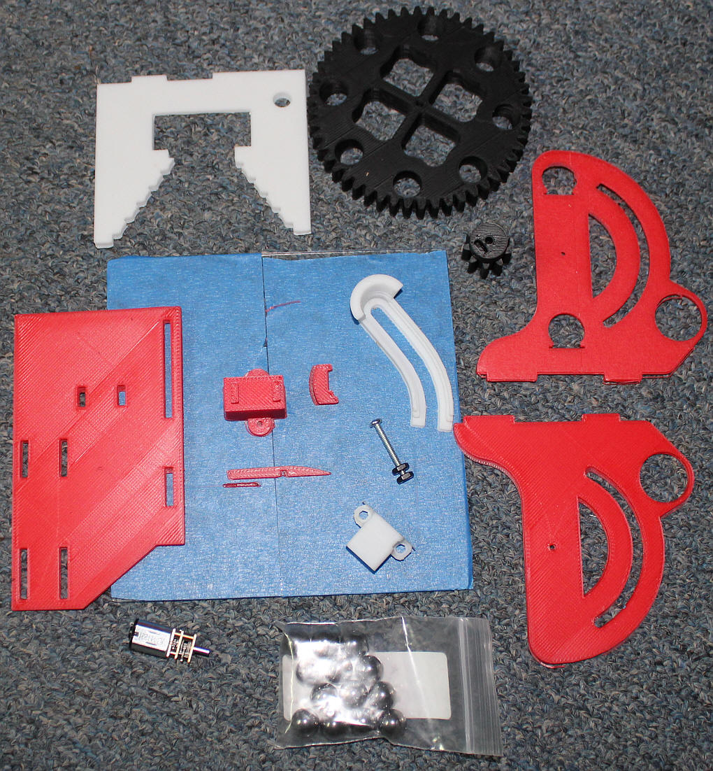
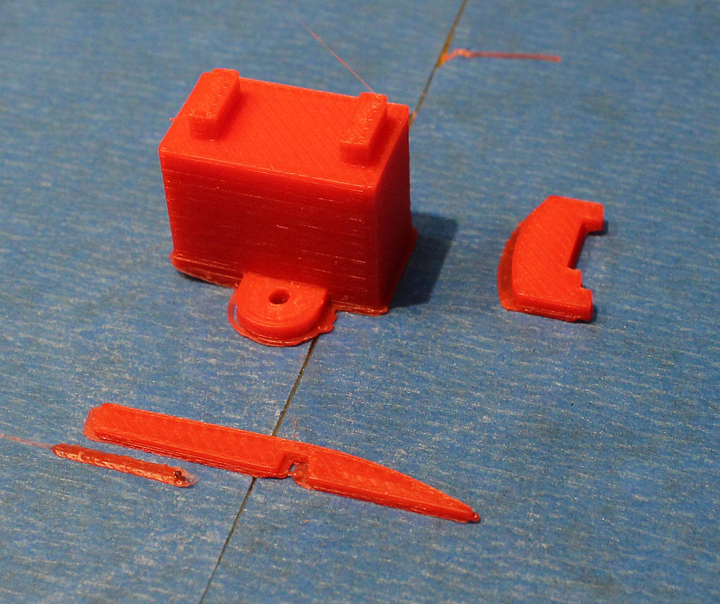
Here are a few of the parts before they were removed from the printing platform, a piece of borosilicate glass covered with blue painter's tape.
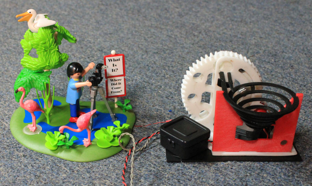
I decided that the Marble Machine would make a nice addition to the G scale layout at Children's Hospital as I was sure that children would be as fascinated by it as I am.
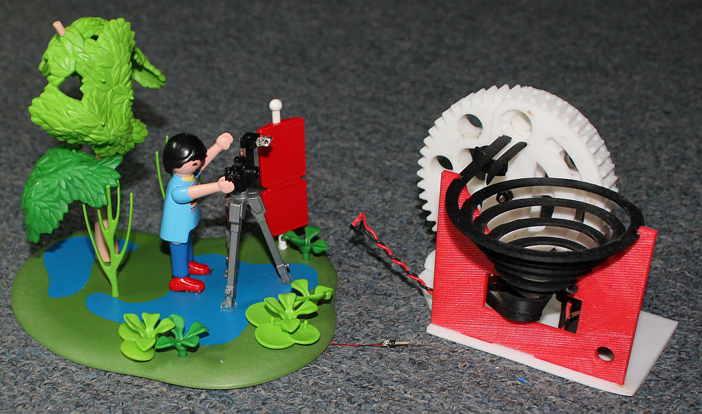
Rather that just put it on the layout with a button to start it spinning for a minute or so I decided that I should create a scene. I explored the various Playmobil offerings (the people on the layout are all from Playmobil) I settled on a photographer using a camera on a tripod, thinking that I could have her taking a photo of the new machine. I decided to add a few bright white LEDs to the camera and to have it flash from time-to-time to show that photos were being taken.
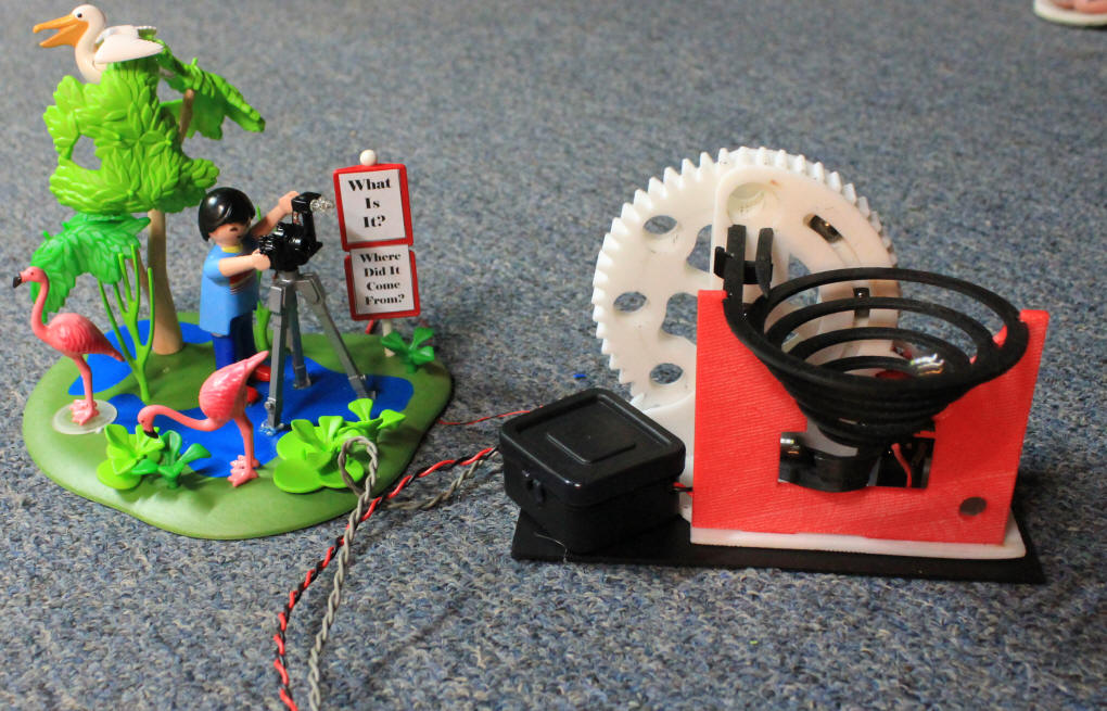
This photo shows the photographer (note the 3mm LEDs in the camera's flash) and the marble machine before the electronics module was added.
Building the Marble Machine
Downloading and printing the marble machine took a day or so as some of the
larger parts took several hours to print. It was assembled and tested
before I glued it all together. It is very important that the three
support sections (one on either side of the large gear and one holding the
spiral) are mounted at 90 degrees to the base. I also found that
lubricating the gear with a spray of Lemon Pledge furniture polish worked
wonders for its reliability.
Once it was working well I glued it all together and tested it for a number of days to make sure it wouldn't jamb or eject balls from the spiral very often. Placing it on a level surface helps this to be accomplished. I also used a round file to remove any roughness from the inside of the ball carrying holes in the large gear.
I found the geared motor at Sparkfun.com for $16.00 and from Suntekstore.com for $7.00 with free shipping. Either will work and they appear to be identical except for price and delivery time.
The ball bearings are 11mm in diameter and can be found on eBay for about $10.50 including shipping.
Adding 3mm LEDs to the Camera
Three 1/32" holes were drilled in the flash attachment on the Playmobil
camera. The two 3mm LEDs were inserted into these holes with both cathodes
(shorter leads) together through the center hole and the anodes through the two
outer holes. The anodes were bent and soldered together as were the
cathodes wiring the two LEDs in parallel. A 60 ohm resistor was wired in
series with the lead to the anodes. This resistor and the 100 ohm current
limiting resistor on the circuit board helped to keep the LEDs from frying when
they were flashed on. I added the 60 ohm resistor after I found that I
killed the first pair of LEDs by giving them too much current.
Very thin (30 AWG) wire was used to supply power from the circuit board to the camera tripod and up one leg of the tripod to the two LEDs.
The Circuit
A PIC microcontroller is used to operate the motor on the marble machine and
the LED flash. A PICAXE could easily be used. The schematic below is
for the PICAXE 08M2. The PIC schematic is virtually identical except for
the programming connections on the left.
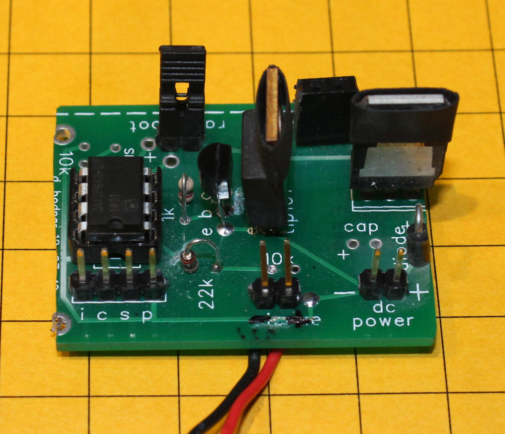
The circuit was built on a board that was designed for my lighthouse and Morse code beacon. Some minor modifications were made to have it control both the motor and the flash LED. I also had to add a trigger input so that the animation would run for a set time each time a visitor pressed the button.
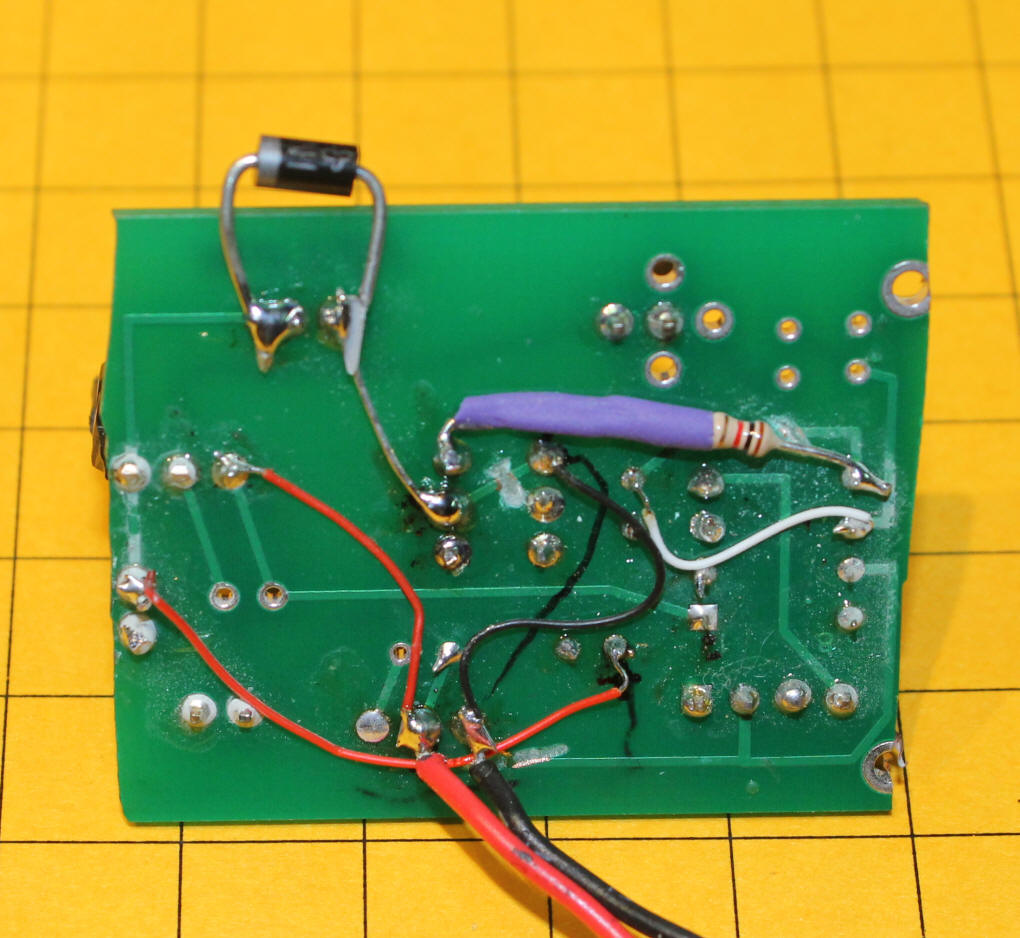
This view of the bottom of the board shows some of the modifications that were necessary to use the Morse code / Lighthouse board. Note the diode at the top. It protects the power transistor that operates the motor from back EMF.
'CHP 3D gizmo & flash camera on 12f683
'd. bodnar 7-13-13
'revised 11-4-09 for Morse Code board - note cut traces & such that are needed
Include "modedefs.bas"
ansel = 0
cmcon0 = 7
Serial_out var gpio.0 'pin 7 'cds photo sensor
LED var gpio.1 'pin 6 led for flash
TIP101 var gpio.2 'pin 5 hpwm 1 = motor
NotUsed var gpio.3 'pin 4
Switch var gpio.4 'pin 3 Start Switch
NotUsed2 var gpio.6 'pin 2 - select pwm settings for LED vs incandescent
Temp1 var word
RndNum var word
Divisor var word
Result var word
RndRange var word
MinNumber var word
TopBright con 120
Serout serial_out,n9600,[13,10,"d. bodnar Ver 1.3 - Camera flash & bearing
gizmo",13,10]
Serout serial_out,n9600,[13,10," - 07-13-13",13,10]
option_reg.7=0 'turn on weak pull ups
wpu = %01010000 'weak pull ups on pin GPIO.4 (Pin 3) & GPIO.6(pin2)
gpio = %01010000 'gpio.4 & 7 input - others outputs
Motor con 1
Minnumber = 1
rndrange = 95
PWMValue con 75'1500
Start:
if switch = 1 then Start 'stay off till button hit
gosub flash
hpwm Motor, 55,pwmvalue:pause 333 'higher speed initial push to start
hpwm Motor, 25,pwmvalue:
for temp1 = 1 to 300 '1000
Serout serial_out,n9600,["Time = ",#temp1," / 300",13,10]
pause 100
gosub getrnd
if result > 90 then
gosub flash
pause 1000 'so we don't get 2 flashes together
endif
next Temp1
hpwm Motor, 0,0:pause 1000
goto Start:
Flash:
low led:
high led: pause 50
low led
return
GetRnd:
Random RndNum
Divisor = 65535 / RndRange
Result= RndNum / Divisor
Result=Result+MinNumber
Serout serial_out,n9600,["RND = ",#result,13,10]
return
Here is the completed animation before installation at Children's. The
grey wire at the front goes to the trigger button on the front of the layout.
The red/black wire is for 12 volts DC.
Conclusion
This has been a fun animation to put together. I expect that the
visitors to the layout at Children's Hospital will enjoy it, too.
Please let me know if you have any questions. dave@davebodnar.com