
Radio Control
Unit for Dimming LEDs
d. bodnar revised 07-23-13
Note- revised reversing unit
and
PICAXE Version of Reverser
and "Dead
Bug" installation
NEW:
Variant of receiver
NEWER: 2nd Variant of receiver
Introduction
For those of us who are always on the look out for a simple and inexpensive way
to remotely control our trains there is a fairly new item that is worth
exploring. It is a keychain remote control transmitter coupled with a
small receiver box that is designed to turn LED strip lights on and off and
control their brightness.
The receiver uses PWM to vary the power getting to the LEDs.
They are available from Tmart.com and Amazon as well as eBay and other vendors. The cost is typically $10.00, sometimes with free shipping. The best price I have found is from banggood.com at less than $6.00 including shipping.
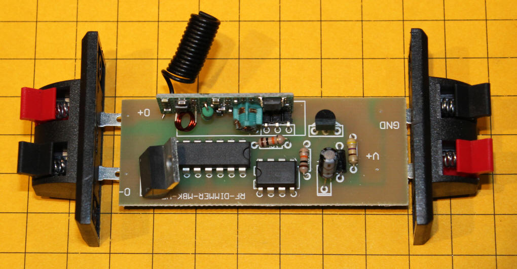
Receiver
The receiver has only two pairs of
connections. One set for input power and one set for output power.
Input power can be provided by any reasonably clean DC power supply such as a
retired laptop power supply or DC wall wart. The input voltage can be from
12 to 24 volts. There is no polarity reversal protection so be very careful that you don't
connect the input power backwards!
The ads say that the unit is good for 8 amps. While this may be true under ideal conditions I would add a heat sink and/or a small fan if I were to go any where near 3 or 4 amps. I have done many tests with an Eggliner and a Bachmann Shay, each drawing between 0.5 and 1.5 amps depending on what is being pulled, and have had no problems.

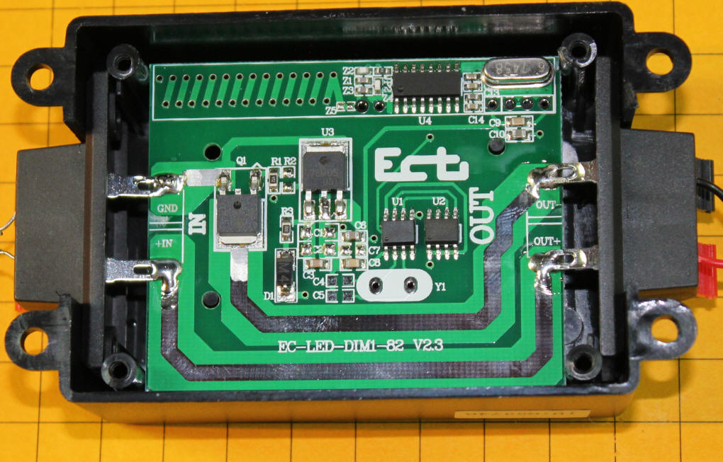
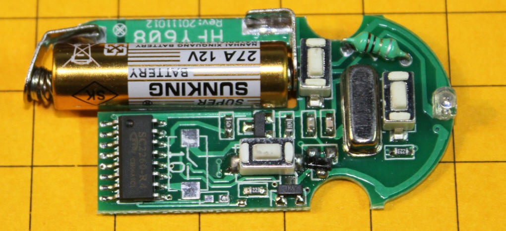
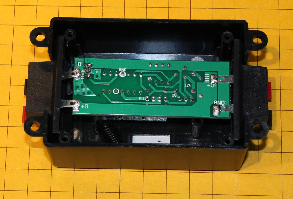
Inside of the Box
If you remove the four screws
under the receiver box you will see the circuitry that makes it work.
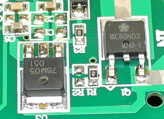
There are two large ICs, a 7805 voltage regulator (U3) and a
ME60N03 Mosfet (Q1).
U4, at the top, is part of the RF receiver section of the unit. U1
has had its identifying markings removed and is likely to be a microcontroller that interprets the
codes from the transmitter and drives the Mosfet.
U2 is a memory chip that probably stores the
units addressing code. The set of holes and diagonal
traces in the upper left corner make up the receiving antenna.
This close-up shows the voltage regulator and Mosfet and their markings.
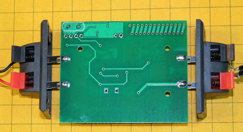
The back of the circuit board contains no components, just a few traces. Note the diagonal traces that make up the rest of the antenna.
Transmitter
The remote control transmitter has
three buttons. A power on/off button and two arrows which increase or
decrease the brightness of the LEDs. Holding the up or down arrow will
repeat the dimming or brightening of the lights.
![]()
Removing three screws from the transmitter gives access to its insides. The large cylindrical object is a 12 volt "27A" battery.
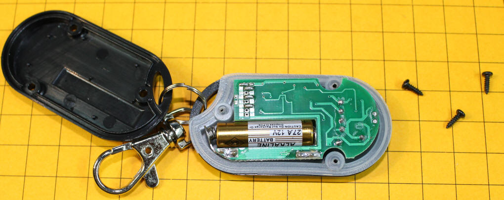
The battery, encoder chip and three switches can be seen from the other side of the board. The LED is at the far right.
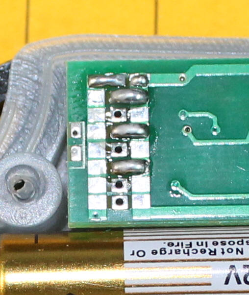
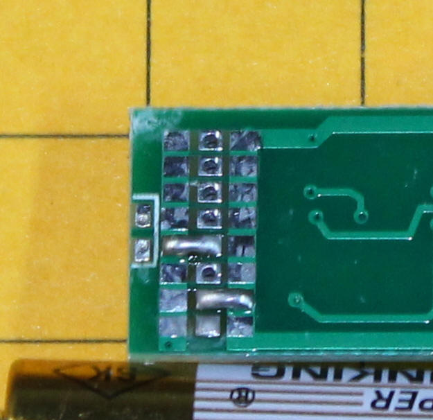
The unique ID for each transmitter / receiver pair is set by soldering across some solder pads as shown in this pair of photos of two different transmitters.
Encoding of Transmitter &
Receiver
The transmitter and receiver are matched during manufacture and each have a
unique serial number programmed into them so that they work with each other and
not with any other pair. Make sure that your two ID codes match as shown
in this photo.
Use with Motors Rather than
LEDs
If we want to use this or similar units with our trains we must add a diode
to the circuit. Motors present an inductive load to the circuitry and
produce a back EMF voltage that can quickly destroy the Mosfet. To protect
against this just solder a diode across the output pins. If you would
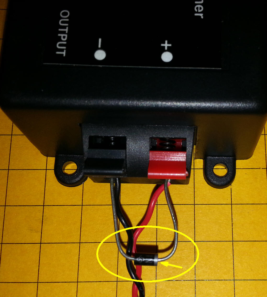
rather not open the box just insert the diode into the two output connectors as
shown. The diode is circled and the band (cathode) is indicated with a
yellow arrow. The diode MUST be inserted with the band to the positive
output terminal. In this photo I have inserted a 1 amp diode similar to
Radio Shack's
1N4004. It proved more than sufficient
for all of my tests. I would choose a 2, 3 or 4 amp diode if I were
working with larger engines.
Range
Inside of my home the range of the unit was at least 40 feet, the distance
across my basement. Outside range was found to be more than 75 feet
when used in a line-of-sight manner. This range is adequate for many
applications. It can be increased by adding an external antenna to the
receiver and/or the transmitter as shown later in this article.
Conclusion
While not a perfect speed control (there is no reverse function) this unit's
price and convenience make it ideal for many small locomotives. I have
tested it extensively with Eggliners, a Shay and other locomotives and it works very
well.
So You Want Reverse, Too? (NOTE: Revised
Reversing Unit is HERE)
While working with this unit I began to think about a simple way to add a
reverse function. There are a number of methods that can be used but I
settled on one that works without any modifications to the receiver or
transmitter, you just insert it between the receiver and locomotive.
The reverse module is composed of a single board that plugs into the output power from the receiver. When power is first applied the relay on the board is in its OFF position and the train goes in one direction. When the power is turned off and back on the circuit wakes up and sets the relay to the ON position sending the train in the other direction. If this sounds familiar it is exactly what Lionel has done for decades with its locomotives using something called an "E Unit".
The only glitch associated with this circuit implementation is the brief jump in the reverse direction that is seen when the relay is set to ON. This is due to the short time between when the microcontroller is first given power and when it can activate the relay. A more complex circuit can alleviate this problem but it is perfectly functional as it is.
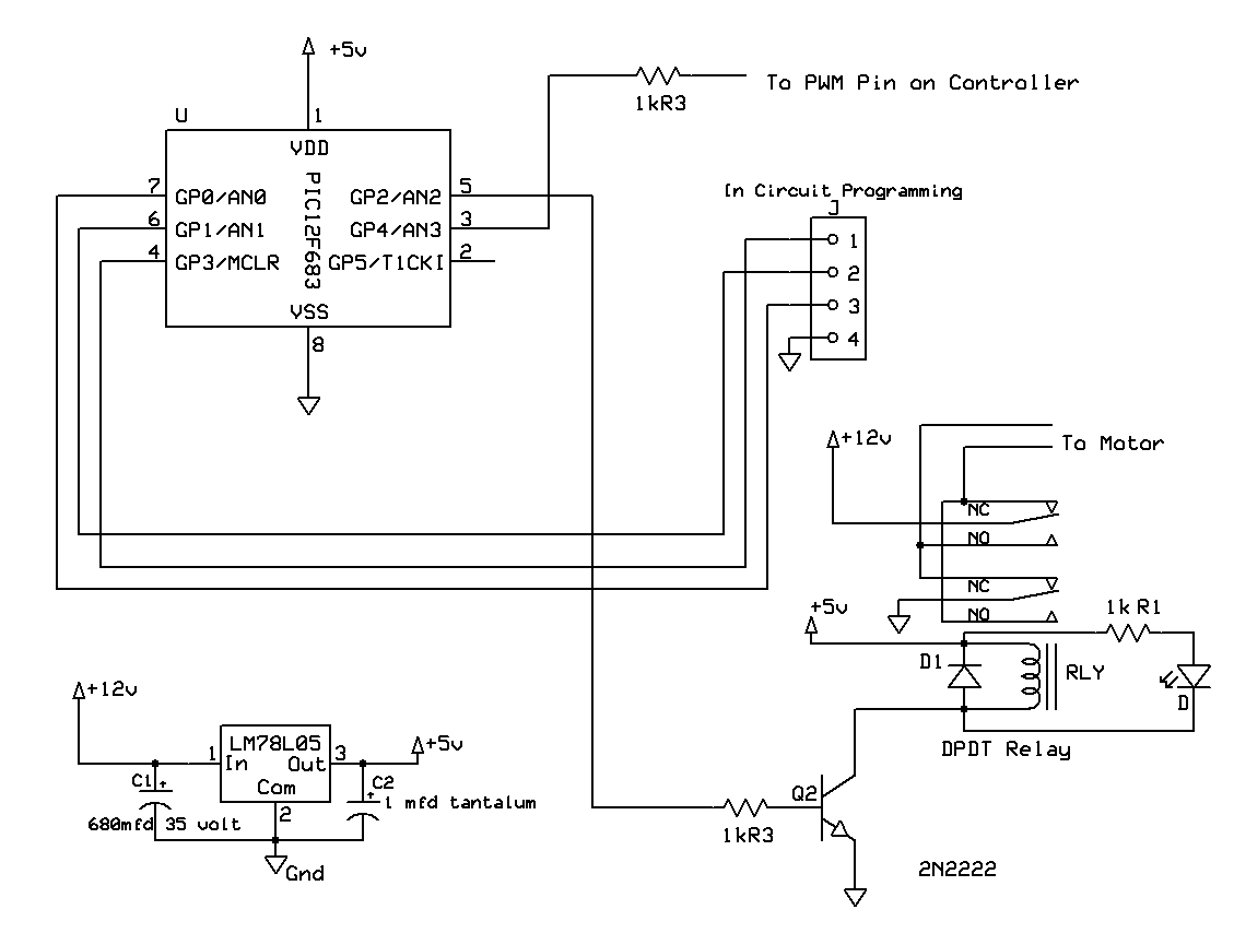
The schematic shows the microcontroller that was used along with the transistor that activates the relay.
The code is very simple. It stores a bit (RelayBit) that indicates the state of the relay and reverses that each time power is applied.
'd. bodnar 6-17-13
'Reverses power (DPDT Relay) along with small RC unit
Include "modedefs.bas"
DEFINE OSC 8
ADCON0 = %100001000 ' Set PORTA analog and right justify result
CMCON0 = 7 ' Analog comparators off
ANSEL = 0 ' Analog select set to digital, pg 69 data
ADCON0 = 0 ' A/D turned OFF, pg 68 of data
OSCCON = %01110000 ' Set to 8MHz
SerialPin VAR porta.0 'pin 13
Relay VAR portc.4 'pin 6
trisa = %00011100
trisc = %00011000
RelayBit var bit
serout serialpin, n9600, [12,"Small Board Timer Test d. bodnar v1.6 E-Unit
(on/off changes DPDT relay for reverse addition to small RC unit", 10,13]
read 0,relaybit
if relaybit = 1 then
relaybit = 0
high relay
else
relaybit = 1
low relay
endif
serout serialpin, n9600, [12,"RelayBit = ",#relaybit, 10,13]
write 0, relaybit
end
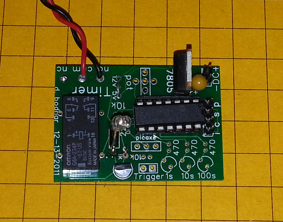
The board is shown here. The circuit is built up on a board that was originally designed for a timer. The relay is at the far left, the voltage regulator in the top right and the PIC processor just below it.
The relay is wired with its output contacts crossed so that the polarity of the DC that is sent to the locomotive is reversed when the relay goes from off to on or on to off.
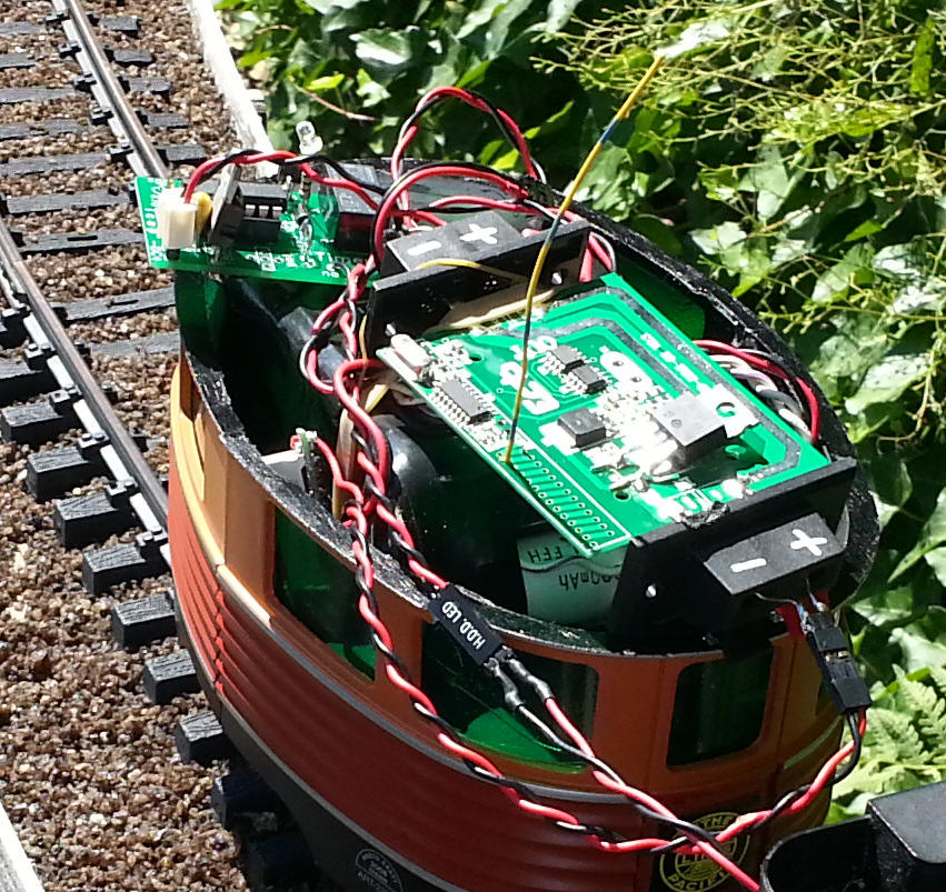
Test Run - Shay
I tested the unit with a two truck Shay that ran around my layout, with some
grades in excess of 3%, for several hours. The battery, circuit board from
the receiver and reversing unit are in the trailing Eggliner cart.
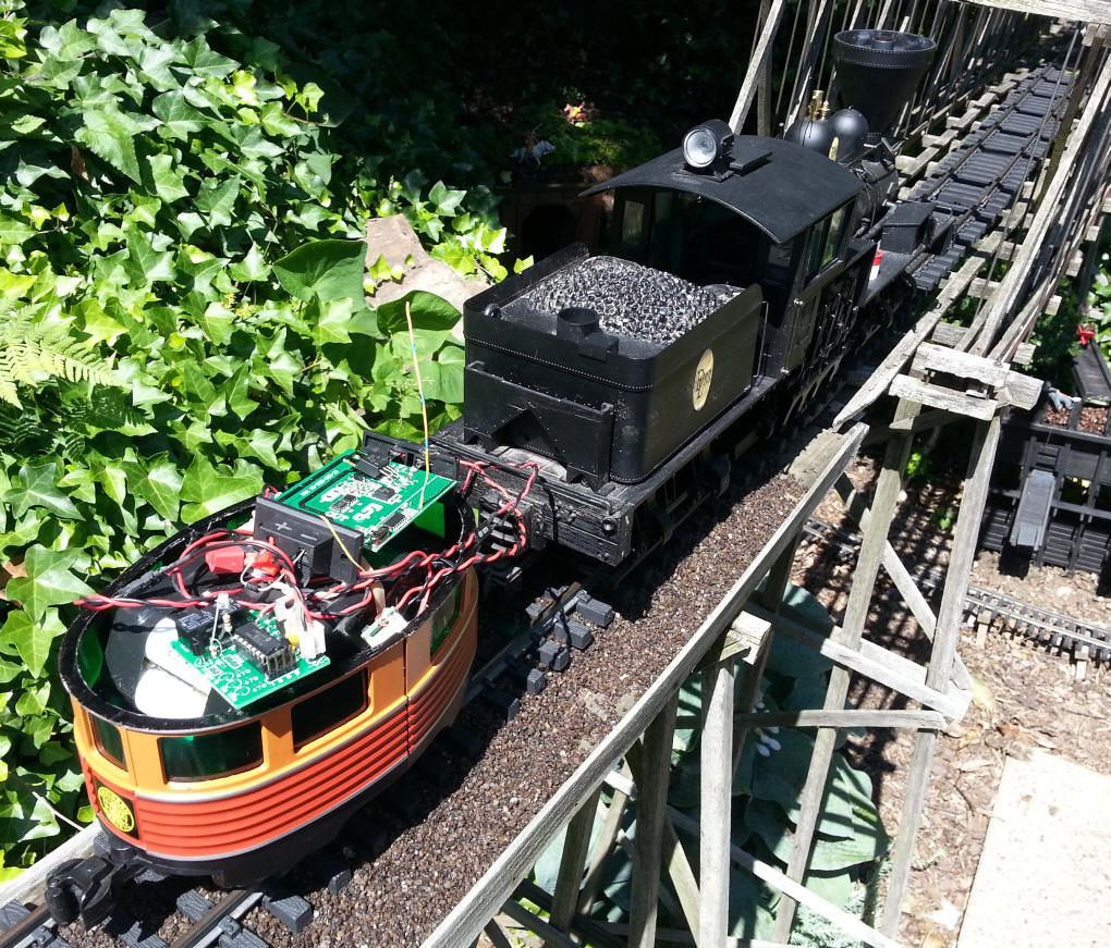
This view shows the circuit board from the receiver (without its case). I added a small vertical antenna which increased the range to a bit over 100 feet. The NiMH battery pack is under the receiver board.
The unit ran the Shay for hours and hours and never missed a beat. If you are looking for a simple and inexpensive radio control unit this is something you should explore!
Please let me know if you have any questions: dave@davebodnar.com .
Revised Reversing
Unit
I found after some more extensive testing that the first reversing unit had
some limitations. It didn't like to work when the power was set to a very
low level and it would sometimes interpret a slow speed as a full off and would
reverse.
The revised reversing unit is always powered on as the microcontroller is connected directly to the input power from the battery. In order to sense if the unit is on or off an A to D (analog to digital) converter that is built into the microcontroller is utilized. It is connected to the PWM output of the microcontroller on the receiver board. This involves some soldering but it also allows you to make up a much more compact unit.
The code is for an 8 pin microcontroller, the PIC 12F683. This is a less expensive and physically smaller chip and has more than enough capacity to perform the functions that are needed.
The most interesting part of the program is the FOR NEXT loop that tests for zero power 20 times before it toggles the relay, reversing the locomotive. This was needed as the AD converter reading at very low power sometimes contains zeros - the test for 20 consecutive zeros helps to guarantee that you don't inadvertently reverse at low speed.
12F683Eunit-read-PWM-v3.pbp
Include "modedefs.bas"
ansel = 0
cmcon0 = 7
Serial_out var gpio.0 'pin 7
Relay var gpio.2 'pin 5 hpwm
Temp1 var word
b1 var byte
SawOff var bit
HaveToggled var bit
RelayBit var bit 'saved so the relay resets to what it was when power was turned
off
Serout serial_out,n9600,[13,10,"d. bodnar Ver 3.0 Morse Board",13,10]
Serout serial_out,n9600,[13,10,"06-20-12",13,10]
Serout serial_out,n9600,[13,10,"E-unit for RC board - saves prior state of
relay",13,10]
gpio = %00011000 '3 & 4 inputs - others outputs
read 0,relaybit
serout serial_out,n9600,["relaybit = ",#relaybit,10,13]
if relaybit = 0 then
high Relay
else
low Relay
endif
havetoggled = 1
sawoff = 0
'if we see 20 zeros then we know it has been off
' in that case set a flag so that the next time we see a non zero
we
' toggle the relay
Start:
for b1=1 to 20
adcin 3, temp1 'read pin 3 PWM
' serout serial_out,n9600,["temp= ",#temp1,10,13]
if temp1 <> 0 then skipout:
next b1
sawoff = 1
'serout serial_out,n9600,["SAW ZEROS!",10,13]
havetoggled = 0
goto start:
SkipOut:
'if b1 > 20 then
' serout serial_out,n9600,["Zeros= ",#b1,10,13]
' pause 1000
'endif
if HaveToggled = 0 then
toggle Relay
if relaybit = 0 then
relaybit = 1
else
relaybit = 0
endif
write 0, relaybit 'save relay state so it starts in the same direction
'if power fails
serout serial_out,n9600,["TOGGLED ",10,13]
HaveToggled = 1
endif
sawoff=0
goto start:
The new reverse board is built on the board that I use for the lighthouse and Morse code beacons. This board does not have a set of holes for a DPDT relay but I have a good number of them in stock and it can easily be modified to accommodate a relay.
The microcontroller on this board is the 8 pin 12F683 seen in the upper right. The only other components are a 78L05 regulator, an NPN transistor and a few resistors and a capacitor. The 1K resistor at the bottom of the board will be connected to the PWM output pin on the RF receiver board. An LED in the bottom left shows whether the relay is latched or not.
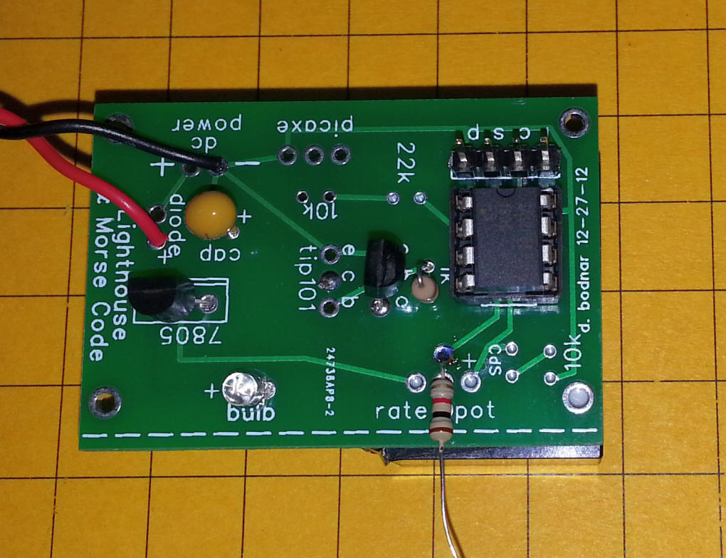
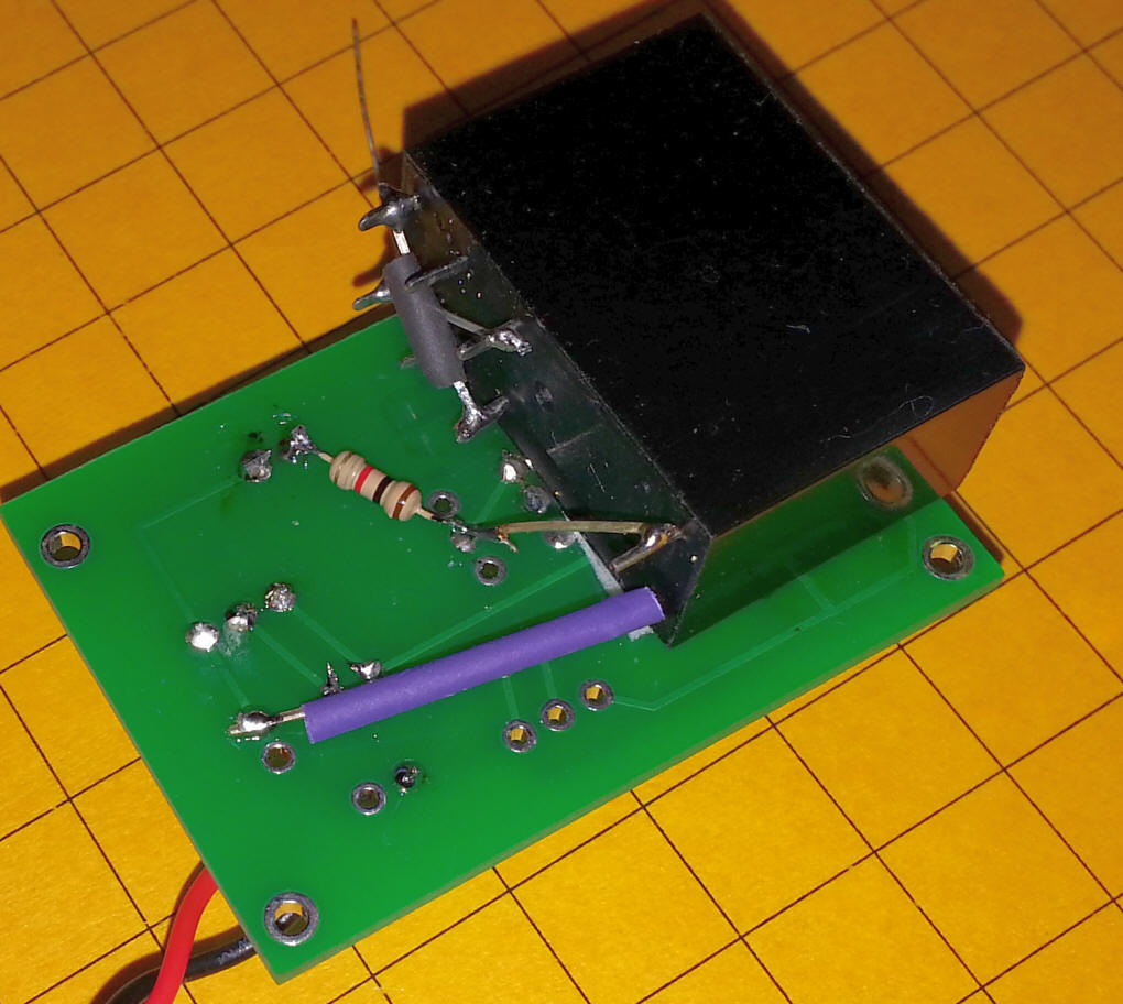
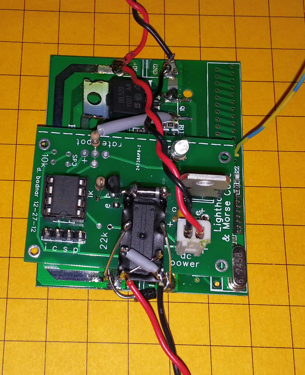
The relay is on the bottom of the board held in place with a bit of foam tape.
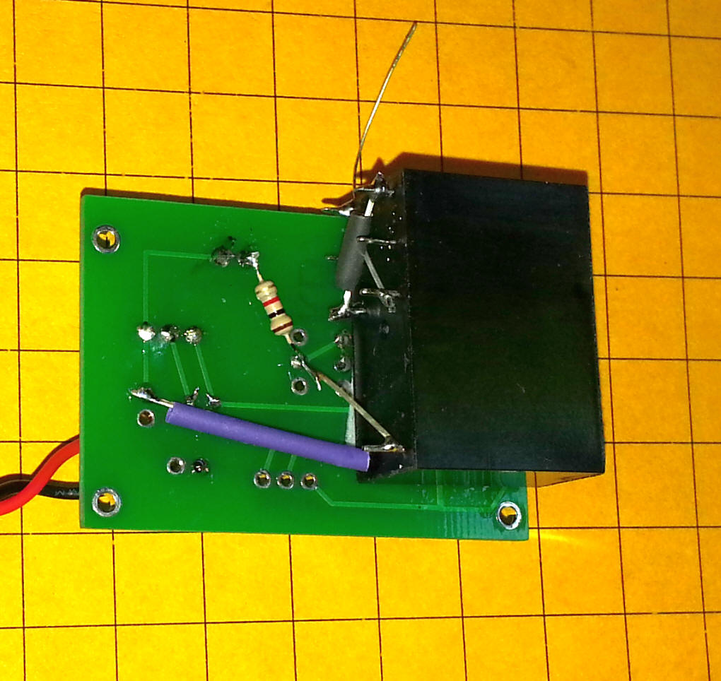
Here is another view of the back of the board.
This is another version of the same board & circuit that utilizes a smaller 5 volt relay. The board has been mounted on top of the RF receiver board with foam tape.
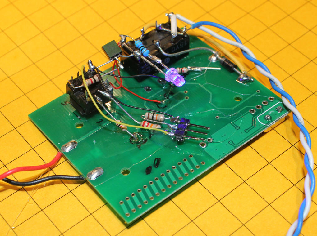
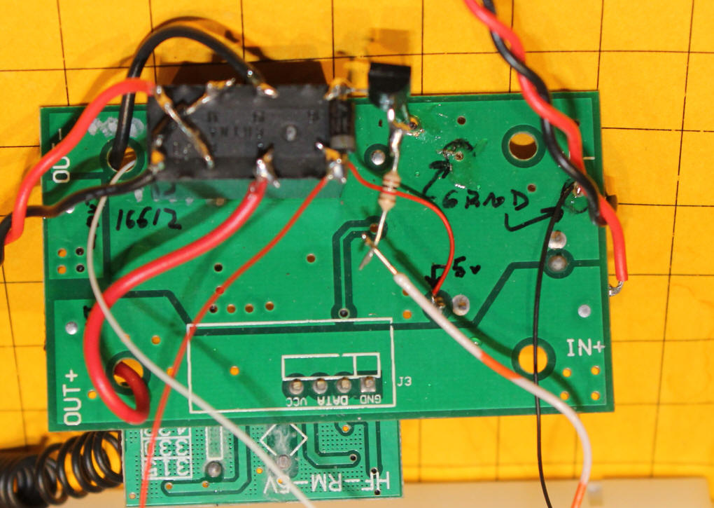
"Dead Bug" Reverse Circuit Installation
Rather than use a separate circuit board a number of components on the radio
control board can be used. This allows us to build up the circuit on the
back of the RC board using as few as seven components. This photo shows
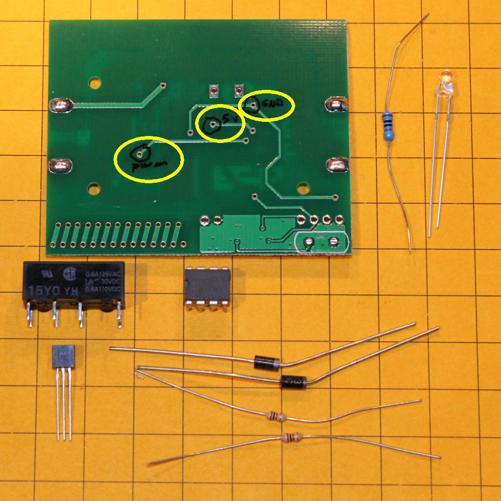
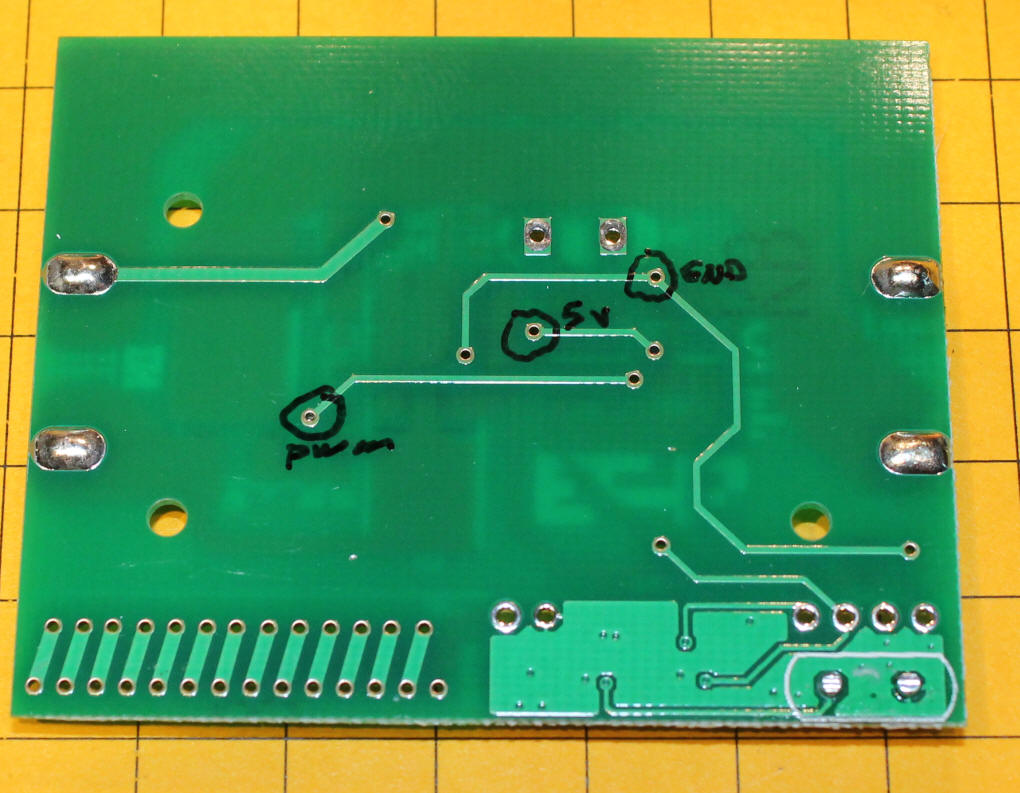
the back of the board with the three connection points that we will use, PWM, 5
Volts and Ground.
The parts below the board are a 5 volt, DPDT relay, a pre-programmed PIC 12F683, a 2N2222 NPN transistor, two generic diodes (I used 1N4003's) and two 1K resistors. There are two optional parts to the right, an LED and a 470 ohm resistor.
First remove the connectors from each end of the board.
Mark the three connection points as shown. I had to scrape a bit of the varnish off of each contact point in order to get a good solder joint.
The relay is glued to the circuit board with its pins up. This is where the "dead bug" construction method gets its name!
Notice the "X" wiring between the four relay contacts on the right. They are circled in red. This wiring pattern is what reverses the polarity when the relay switches on or off.
There are two diodes, circled in yellow. They must be mounted with their banded end, the cathode, oriented as shown. The center pair of relay pins go to the output power from the RC board. One of the diode's long leads is used to connect to one side and a yellow wire goes to the other.
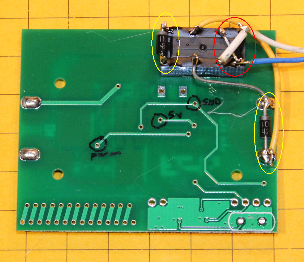
Power goes to the relay and PIC controller as shown. The PIC is also glued to the board "dead bug" style. Red wire is used for 5 volts and black for ground.
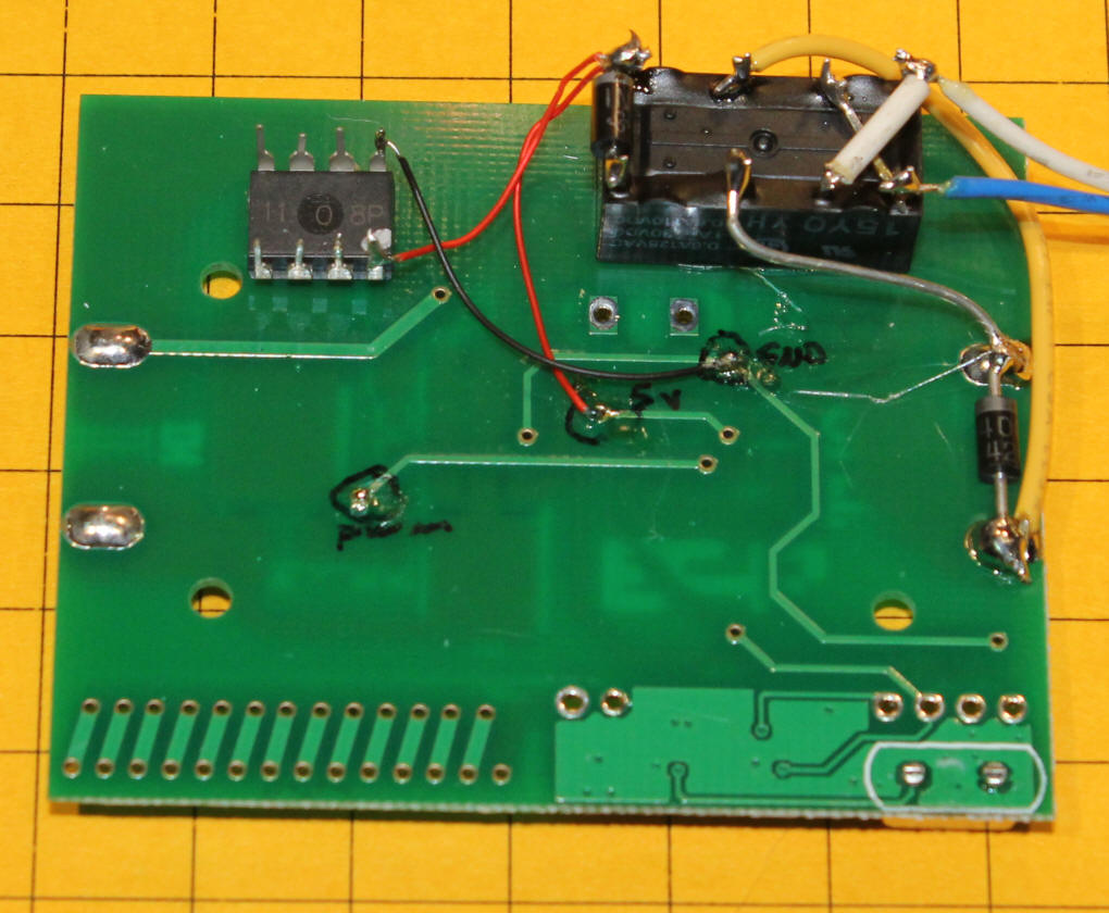
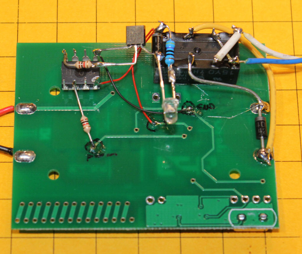
The transistor that operates the relay is added along with a 1K resistor that goes to its base from pin 5 on the PIC. The transistor must be oriented as shown with its emitter going to ground and its collector going to the relay. The PWM connection goes from the contact on the RC board to pin 3 on the PIC via a 1K resistor. This connection is used to detect if the power to the motor is on or off.
![]()
The optional LED and current limiting resistor has been added. It lights when the relay is on and goes out when it is off. I would recommend extending the LEDs connection wires so that it can be placed where it can be seen easily.
If you would like to give this circuit a try the parts are readily available. If you have the capability to program a PIC 12F683 I can supply the compiled code. If you do not I can program a chip for you and send it for $3.00 plus shipping.
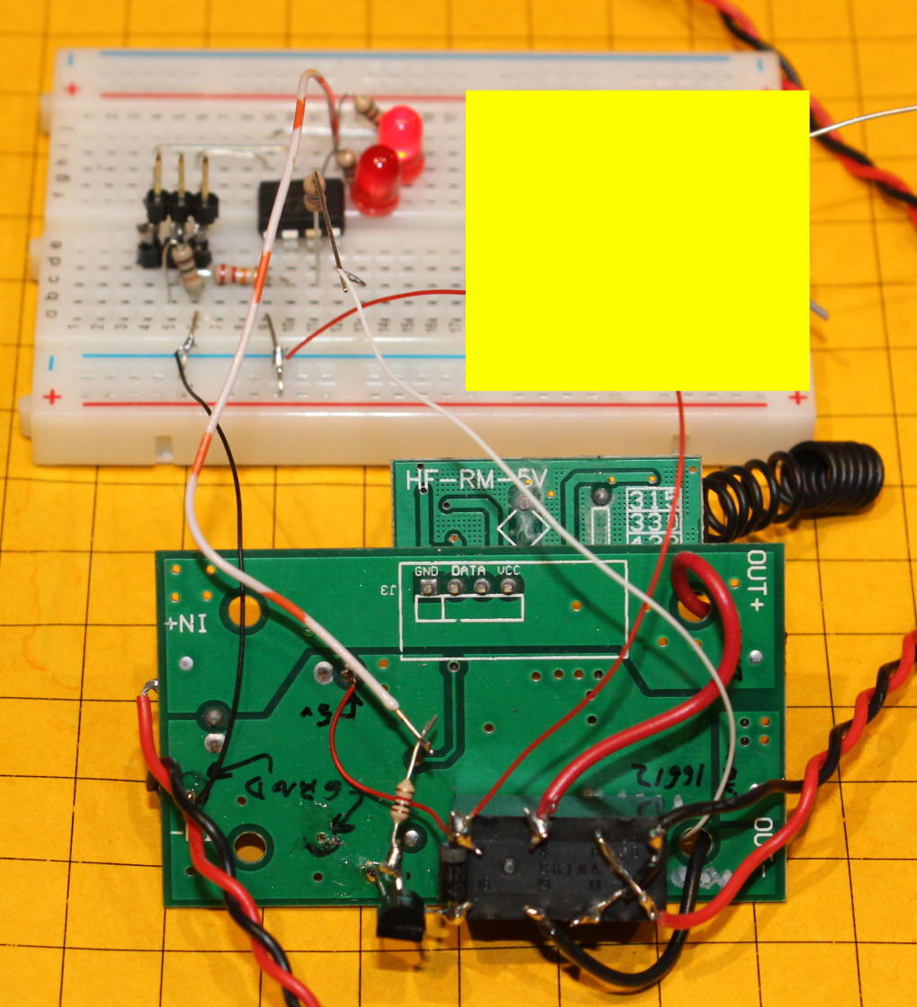
Using a PICAXE for the Reversing Circuit
The installation show above uses a PIC microcontroller. Although
similar to a PICAXE it is much more expensive to program. See
this
article for details on the differences between these two chips.
The schematic here is for the PICAXE version of the program. It is almost
identical to the PIC 12F683 schematic. The main difference is the
programming connection to pins 2 and 7.
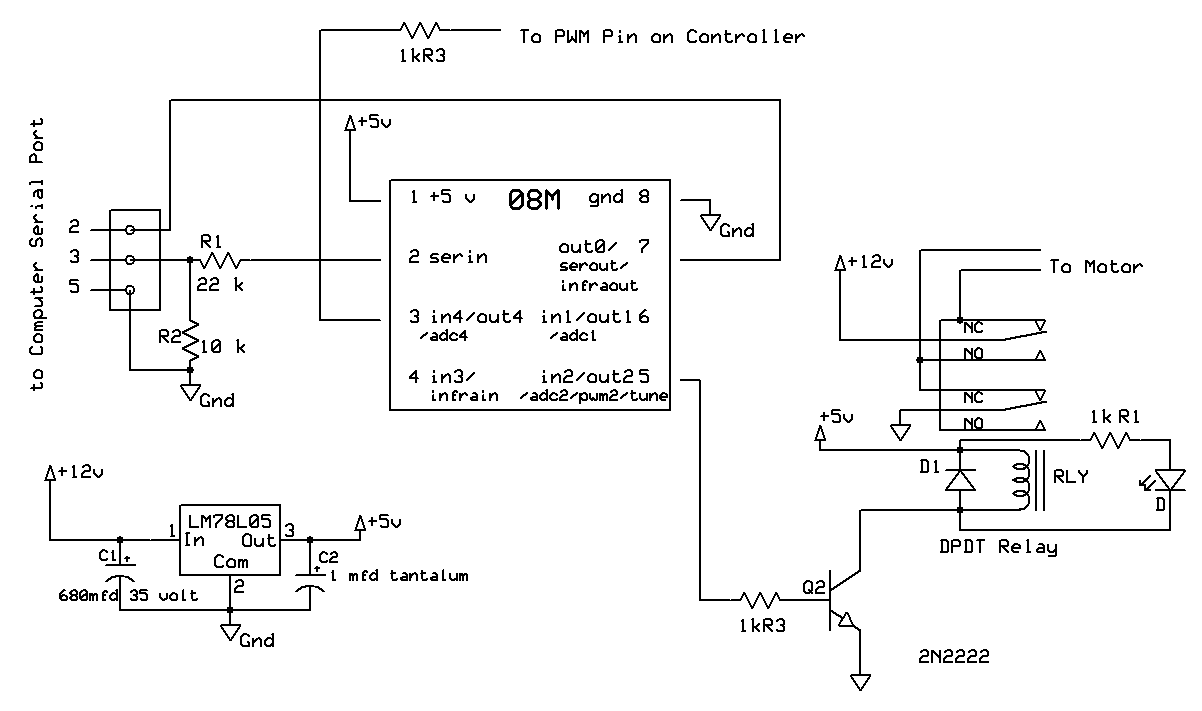
The code for the PICAXE is also very similar and works just as well.
'08M from 12F683 code
'd. bodnar 7-3-13
Symbol Relay = 2 'pin 5 hpwm 1
Symbol Temp1= w8
Symbol temp2 = b2
Symbol SawOff =bit1
Symbol HaveToggled = bit2
Symbol RelayBit = bit3 'saved so the relay resets to what it was when power was
turned off
Sertxd (10,13,"d. bodnar Ver 1.0 E-Unit",10,13)
Sertxd (10,13,"07-03-13",10,13)
Sertxd (10,13,"E-unit for RC board - saves prior state of relay",10,13)
read 0,relaybit
Sertxd ("relaybit = ",#relaybit,10,13)
if relaybit = 0 then
high Relay
else
low Relay
endif
havetoggled = 1
sawoff = 0
'if we see 20 zeros then we know it has been off
' in that case set a flag so that the next time we see a non zero we
' toggle the relay
Start:
for temp2=1 to 20
readadc c.4, temp1 ''read pin 3 PWM
if temp1 <> 0 then skipout:
next temp2
sawoff = 1
havetoggled = 0
goto start:
SkipOut:
if HaveToggled = 0 then
toggle Relay
if relaybit = 0 then
relaybit = 1
else
relaybit = 0
endif
write 0, relaybit 'save relay state so it starts in the same direction
'if power fails
Sertxd ("TOGGLED ",10,13)
HaveToggled = 1
endif
sawoff=0
goto start:
Constructing the PICAXE Version
Wiring and assembly for the PICAXE version is almost identical to that for
the PIC. In fact, the installation that I did with the PICAXE shown below
was done by removing the PIC chip and soldering the same wires to the same pins
on the PICAXE. The only differences are that I plugged the PICAXE into an
8 pin socket before soldering (not necessary but it makes it easy to switch back
to the PIC) and the addition of the 3 pin programming header near the center of
the board. Its left pin (yellow wire) goes to pin 7 on the PICAXE.
The center pin goes to pin 2 via a 22K resistor (red, red, orange color code) as
well as to a 10K resistor (brown, black, orange) that connects to the right pin.
That pin also connects to ground via a black wire.
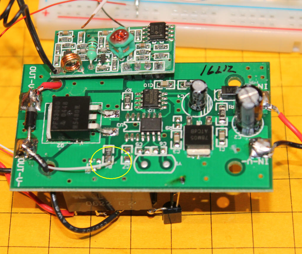
Variant of the
Receiver
BangGood.com sells a unit
that looks the same but has a different receiver. The first clue that
there was a difference was that there was no ID sticker on the receiver or
transmitter. I tested the two units that I purchased and they both worked
with either transmitter.
When I opened the transmitter it was the same as the others but there were no solder pad jumpers to set it as a uniquely coded transmitter. The receiver is dramatically different and has no coding.
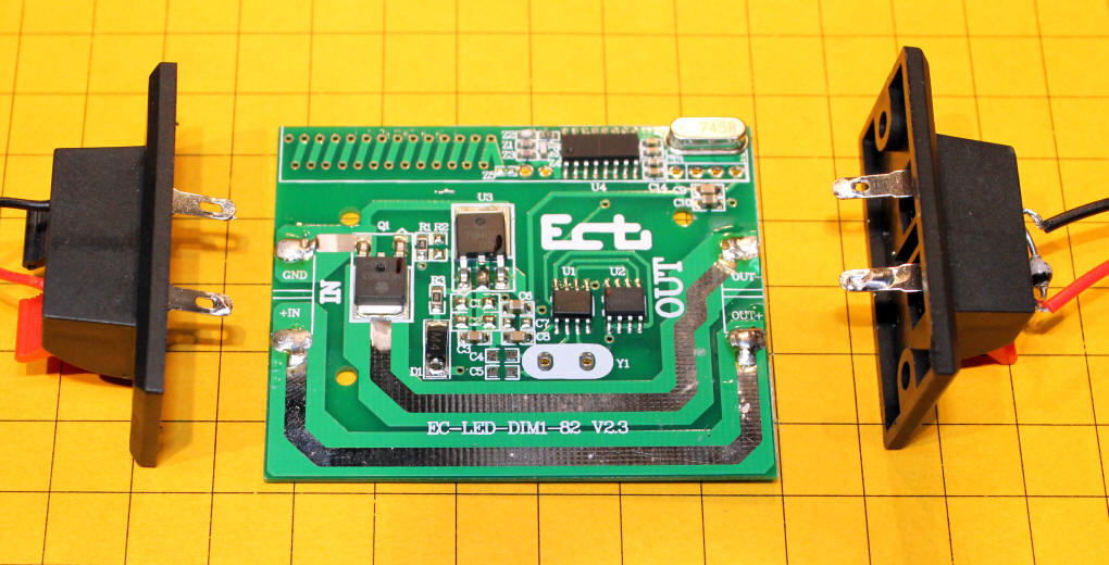
This view of the other side of the circuit board shows the dramatic difference between the units. They are functionally the same but not well suited to the on-board reverse unit shown earlier.
Variant #2
Another variant was received from an eBay vendor. This one has the
receiver on a separate board. The photos below show how to hook up to the
connections that you need to install the reversing circuit.
There is the front of the board. The receiver module is at the top. Note the yellow circled connection. This is where the white wire picks up the PWM signal. Power comes in from the right and leaves to the left.
This view of the back of the board shows where ground and +5 volts can be picked up. The relay and transistor are at the top.
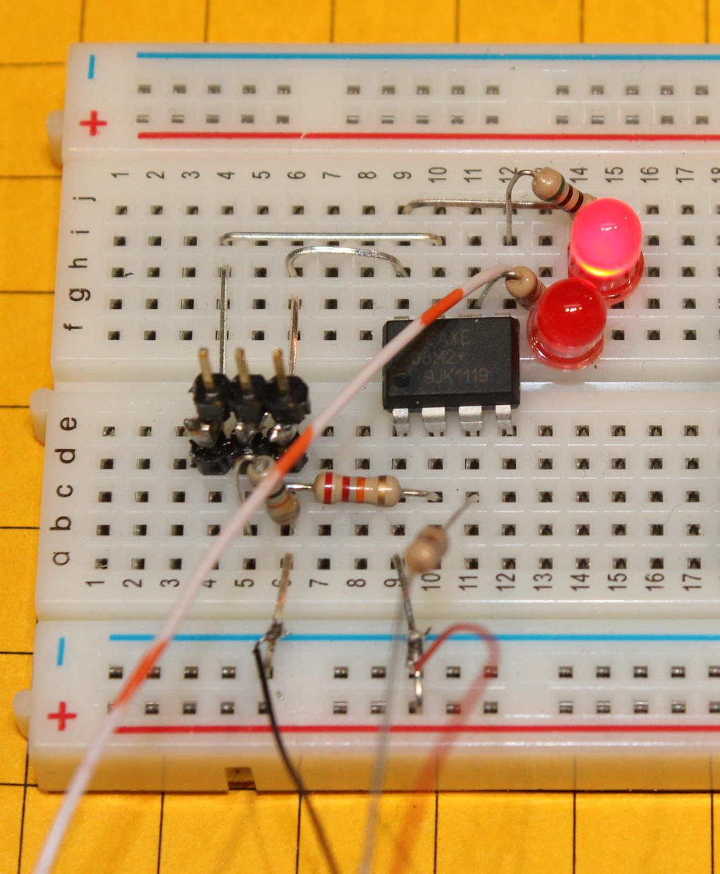
Here is a test circuit that has a PICAXE on a prototype board. The yellow rectangle obscures another project on the board. The relay is controlled by pin 5 and the PWM connects to pin 3.
Here is a close-up of the PICAXE.
Conclusion
This inexpensive RC system has proven to be an interesting thing to explore
and to modify for model railroad use. Even if you choose to skip the
reverse option I think you will enjoy this cost-effective way to bring radio
control to many engines, large and small.
Please let me know if you have any questions