Another Inexpensive Radio
Control Experiment
revised d. bodnar 12-27-2015
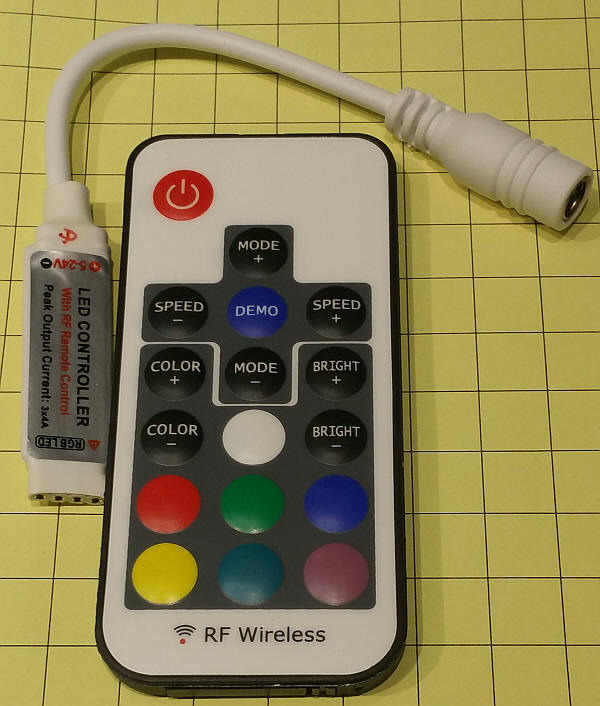
| Introduction There are a number of inexpensive (< $10.00) radio control units that have come to market that may have model railroad control applications. These controllers are designed to connect to LED strip lights, either of a single color or of the RGB variety (R=red, G=green, B=blue) I have done some experimenting with a few of the devices I have found on eBay, Amazon and from other vendors. Some of these devices communicate from the transmitter to the receiver via infrared signals and other use RF (Radio Frequency). I have limited my experiments for this article to RF devices as they generally have greater range and can operate around barriers (IR units require line-of-sight operation) The devices to be explored also are designed to operate RGB LEDs so that one color can be used to control the engine speed while another color is used to toggle a DPDT (Double Pole Double Throw) relay to reverse the motor's direction of rotation. If you have no need to reverse your train you can use one of the simpler, one color controllers.
|
| Selecting an Appropriate Device Some of these LED controllers are better suited to use with trains than others. For example, the unit pictured here can only vary the brightness of the LEDs in 6 steps. While this may be OK for LEDs it is not for an engine's motor.
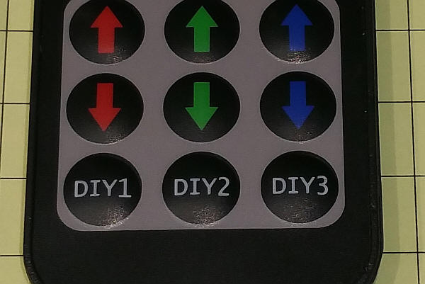
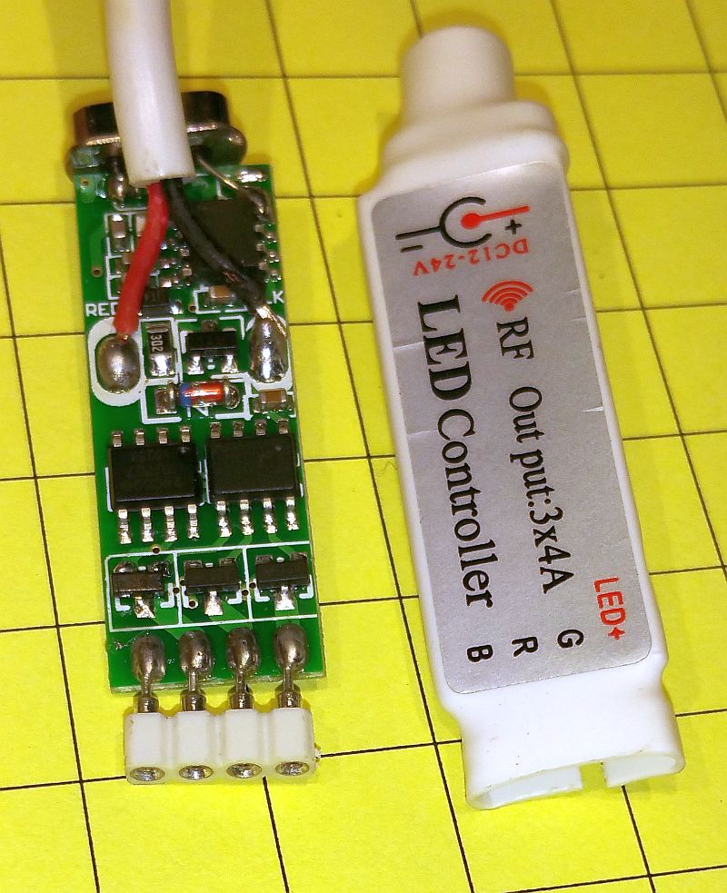
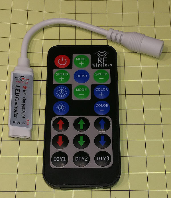
The unit pictured at the top of the page has three buttons labeled DIY1, DIY2 and DIY3. These buttons can be used to set the individual brightness level for each LED color in many discrete steps.
To use the DIY keys just press one and set the red, green and blue to any level you want. When you return to that key it will return the LEDs to the selected levels. I set DIY1 to max Red, which turns on the relay, nearly max Green for high speed and did not use the blue at all. The DIY2 key was set as the DIY1 except that the red was set to minimum to turn the relay off. That way pressing DIY1 went in one direction and DIY2 went in the other direction. |
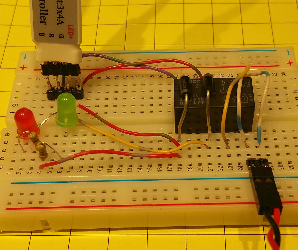
| The Circuit The schematic shows the output from the LED Controller going to a DPDT relay. Diodes D1 and D2 protect the internal components in the controller from back EMF from the engine's motor and the relay. LEDs D3 and D4 and resistors R1 and R2 are optional. They are useful during development as they give a visual indication of the state of the relay and the power going to the motor. The input power to the LED Controller is not shown on the schematic. I used 18 volts for a G scale engine. Anything from 12 to 24 is acceptable.
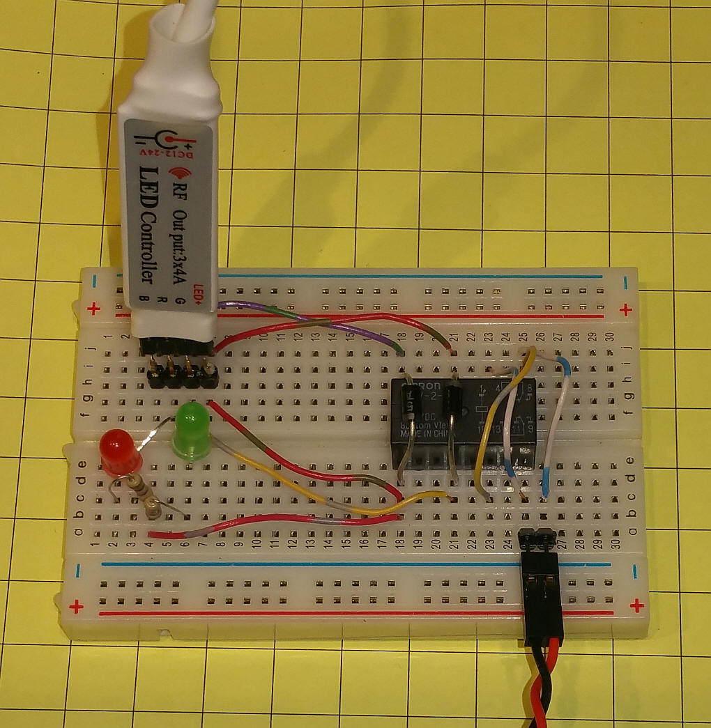
The prototype circuit is shown here on a solderless breadboard. The four terminals on the LED Controller are labeled "LED+", the common positive connection, "G", for Green, "R", for Red and "B", for Blue. The connections on the solderless breadboard closely follow the schematic. The relay (black object to the right) is a 12 volt, DPDT. The two diodes go over the relay - note the silver bands on them and their orientation.
Power to the track is via the twisted red/black wire in the bottom right. The two LEDs are optional.
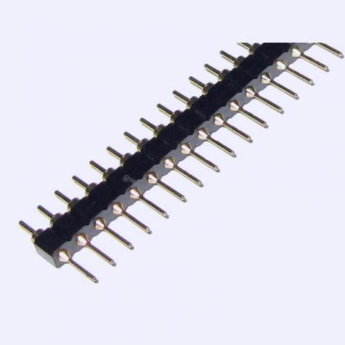
That the 4 pin connector on the end of the LED controller will not accept the most common size of 0.1" headers. They fit into machined pins like the ones here: http://www.ebay.com/itm/5x-40-pin-1-row-0-1-PCB-Male-Machined-Round-Header-DE1557-/310891410876?hash=item48629275bc:g:Fz0AAOSw-jhUHNTp
|
|
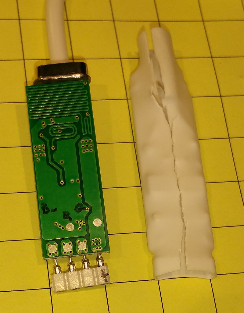
These photos show the receiver with the heat
shrink removed. The three small devices at the bottom of the
board are MOSFETs (like transistors) that control the brightness of
the LEDs. Their spec sheet says that they are good for a
maximum of 2 amps each even though the seller says they are good for
4 amps. The maximum voltage on the spec sheet is 20 while the
seller says 24 volts is OK. The two chips near the center of the board are the microprocessor and memory chip. the IC at the top is the RF receiver and the crystal that determines the frequency is at the very top.
|