LED Display Timer Board
d. bodnar revised 9-12-13
New information on board with separate trigger connection
Introduction
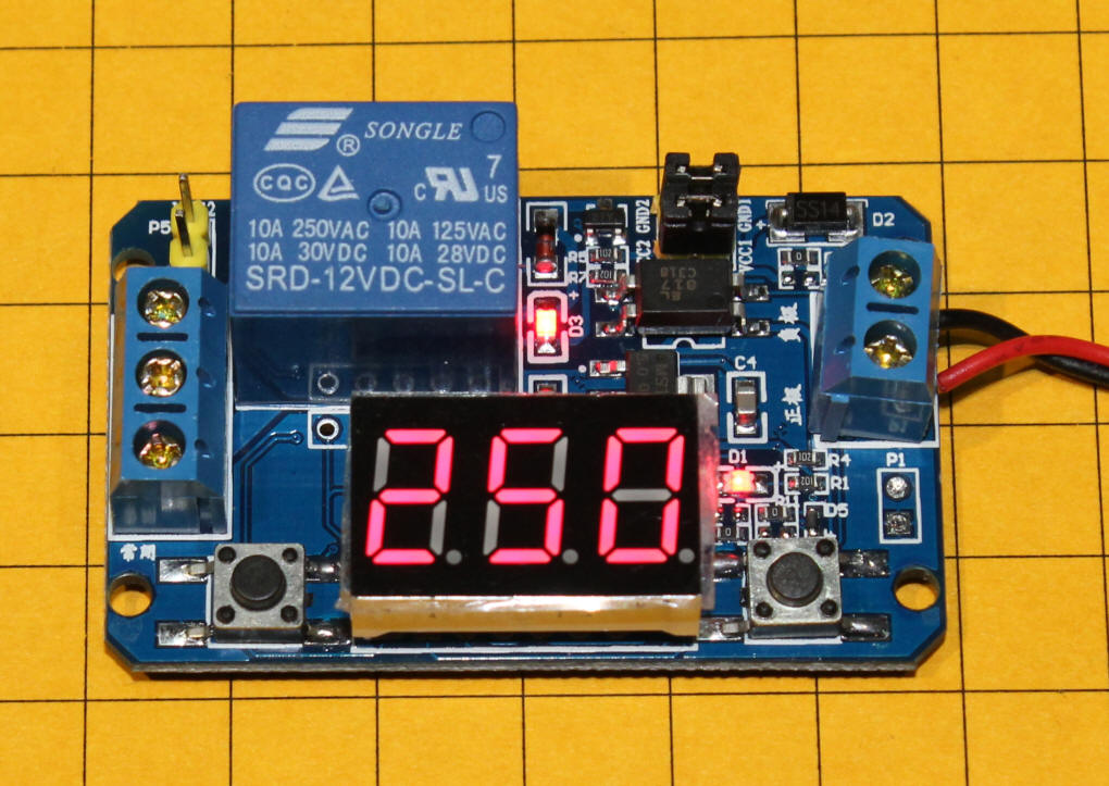
I recently came across a single board timer with a 3 digit LED display at a
good price that appeared to have capabilities that make it ideal for many model
railroading applications. It is designed to activate a relay for a set
number of seconds then turn the relay off for another set number of seconds.
Both of these times (time on and time off) can range from 1 second to 999
seconds and are clearly shown on the red LED display making setup a snap.
After the on and off times are set they are stored so that upon applying power the unit immediately activates the relay for the set ON time and counts down on the display. When it reaches zero it turns the relay off and counts down the OFF time. It repeats this sequence until the power is removed.
I can see using this timer to operate animations or other devices that you want to run for a time and rest for a time. It would, however, be more useful for me if it did have a trigger input that would activate the relay when a button was pressed and keep that relay ON for the set time. Even though the unit does not provide that function as delivered it can easily be adapted for this purpose as described later on in this article. I have also added information about a 2nd timer that already has such a trigger function build in. It is described at the end of this article.
Distributors
These units are available from a number of on-line sources including
SuntekStore where it is item # 14007844
and sells for $7.99 including free shipping. The price shown on their web
page indicates a regular price of $12.99 so the discounted price may be for a
limited time.
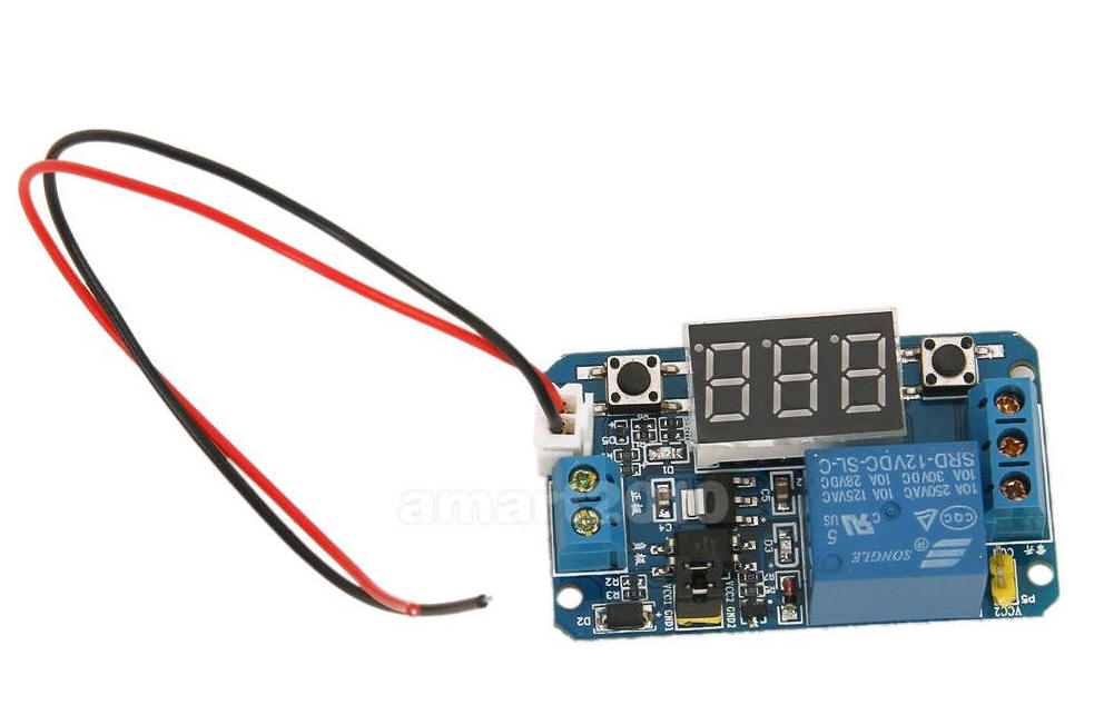
You can also search Google and / or eBay for
and you will find the boards. Note that some of the boards include a 2 wire (red & black) cable (shown in the photo below) that appears to be a trigger - I have not evaluated this unit yet and can't determine how it works and how its operation compares to the unit described here and the documentation on the web sites that sell this unit don't say what these wires do.
Programming
When the unit is delivered it is set to 10 seconds on and 10 seconds off.
To change the time follow these steps.
To change the ON time:
To change the OFF time:
Modifying the wiring to add a Trigger
As mentioned earlier there are situations where you might want a particular
animation or crossing signal to come on and remain on for a set time after a
button is pressed. This is how the trains and animations at Pittsburgh's
Children's Hospital train layout operate. There are eight buttons spread
out on the front of the layout. Each starts up a train, trolley or
animation for a set time.
Even though this board does not have a trigger it is easy to wire it so that pressing a button will activate the timer, having it stay on for the set ON time.
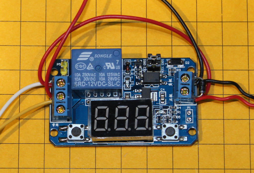
The diode (D1) on the line that goes to the 12 volt load is optional but should be used if the load is inductive, like a motor or device with a magnetic coil.
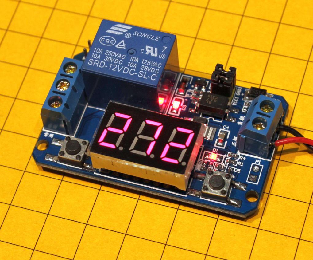
This photo shows the unit with the trigger rewiring shown in the schematic. The black / red wires at the top go to 12 volts DC. The yellow / white wires to the left go to the trigger switch and the red / black wires to the right go to the load. Note that a small diode has been added for inductive loads.
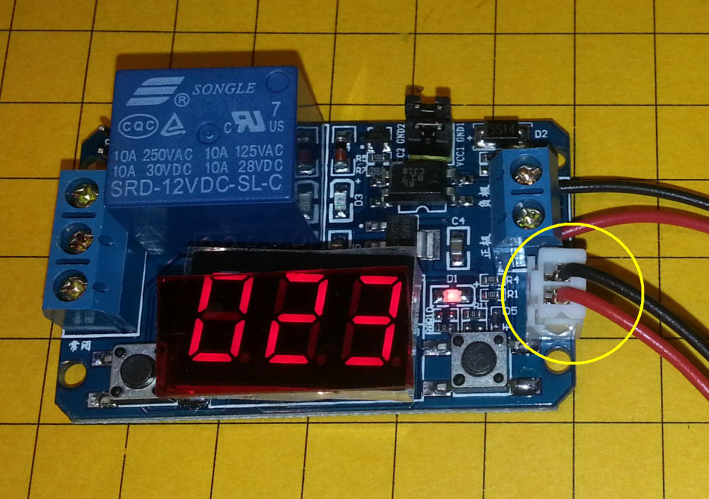
As mentioned earlier in this article I had seen a second board that had two contacts to the right of the LED display. In the photo above they are circled in yellow. None of the descriptions of the board on web sites gave any indication of what these contacts did other than the addition of the word "trigger" to the titles of the advertisements. Invariably the functions of the boards with the two extra wires were the same as the one described earlier.
I ordered two of these "trigger" boards from SuntekStore, item # 14007846, and was pleased to find the extra wires are, indeed, a trigger that closes the relay for a time that you set on the LED display.
Programming
When the unit is delivered it is set to so that connecting the trigger
wires activates the relay for 10 seconds.
To change the time follow these steps.
To change the time that the relay remains ON:
Operation
Once the time has been set briefly connect the two trigger wires and the
relay will be turned on and the count down will begin. Once the display
reaches zero the relay will go off until you trigger it again.
If you connect the trigger wires while the relay is on the time will be reset to its original setting and the countdown will begin again.
Conclusion
I think you will find these small, inexpensive timer boards to be an ideal
solution to many model railroad timing needs. Please let me know if you have any questions or have anything to add to his
page - email:
info@trainelectronics.com