Track Pickup for Lighting Buildings with LEDs
d. bodnar revised 6-12-14
 Introduction
The Pittsburgh Garden Railway Society sets up layouts at a number of
community events and train shows each year. We have an assortment of
buildings that sit along the track and I like to see lighting inside of them as
it adds to the realism of the display. Options for powering the lighting
for these buildings include running wires to each building from some central
location or operating from batteries. I am not a big fan of either of
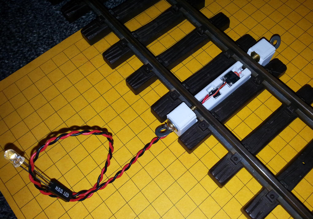
these methods of getting power to the buildings. Since each building is
quite close to the track and the track has power most if not all of the time, I
decided to experiment with pickups that would feed power from the track to LEDs
that would light the buildings.
Design - Electrical
In order to use track power to light LEDs two things need to be addressed.
First, the track power is DC but it can be of either polarity depending on the
direction of travel of the train. We also need to limit the current that
gets to the LEDs to keep them from self-destructing.
A small bridge rectifier can be employed to provide DC
power of fixed polarity and a small integrated circuit, the CL2N3, can be used
to limit the maximum current to 20 mA. For more information about the
CL2N3 see:
http://www.trainelectronics.com/LED_Articles_2007/LED_104/index.htm
The circuit shown here can power a number of white or
warm white LEDs, especially if they are wired in series. If more current
is needed two or more CL2N3's can be wired in parallel as shown in the
aforementioned article. You could also skip the CL2N3 and just use current
limiting resistors.
If you are using identical LEDs you can wire them in
series or parallel as shown here:
SERIES
PARALLEL
Design - Frame
The next issue was designing a way to pull power from
the track. Standard track pickups such as those sold by LGB, Bachmann and
other vendors are certainly an option. Since I have a 3D printer I decided
to design a track pickup and use it to house the electronic components as well.
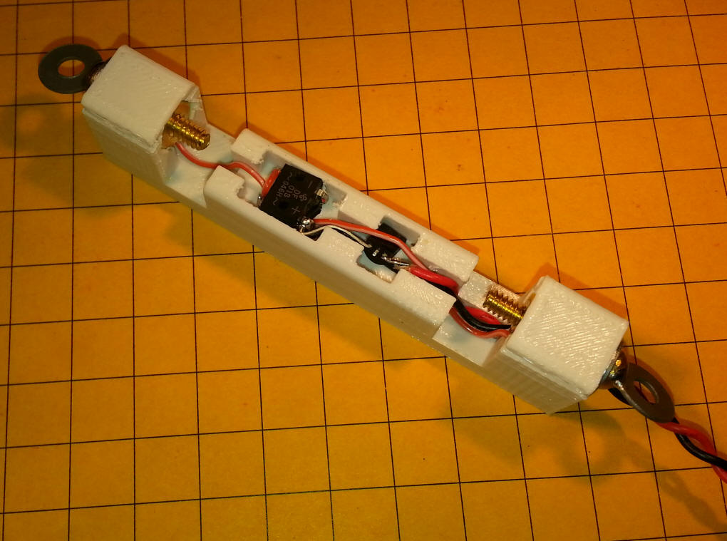
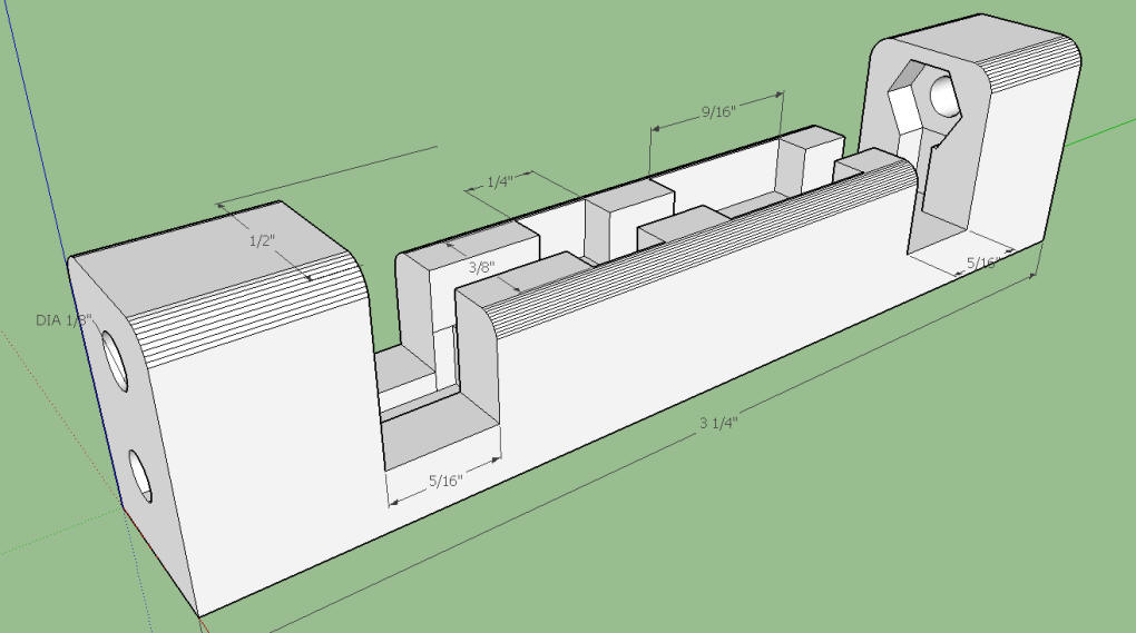
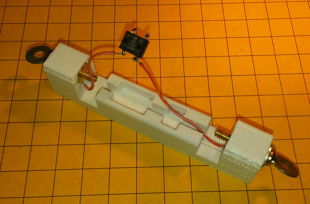
The design, from SketchUp, is shown here. Room
for brass nuts & bolts is provided at each end and two cavities in the plastic
accommodate the bridge rectifier & CL2N3.
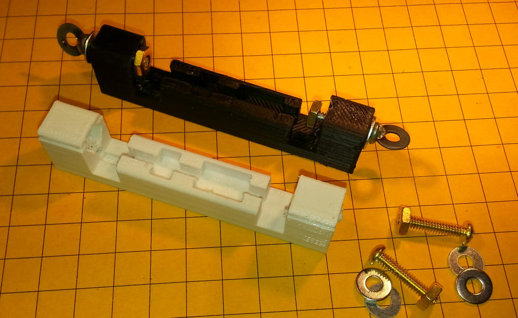
Materials
- Brass Screws
6-32 x 3/4"
- Brass nuts 6-32
- Washers #6
- 20 mA LED driver -
CL2N3-G -
Mouser
- Bridge rectifier -
DF01S-E3/45
- surface mount -
Mouser
- 3D printed frame -
STL file is here
- Stranded hookup wire
Construction
Since the 3D printer will partially fill the holes at each end of the frame
ream them out with drill bits. The holes for the bolts are 9/64" and the
access hole that wires pass through is 1/8" in diameter.
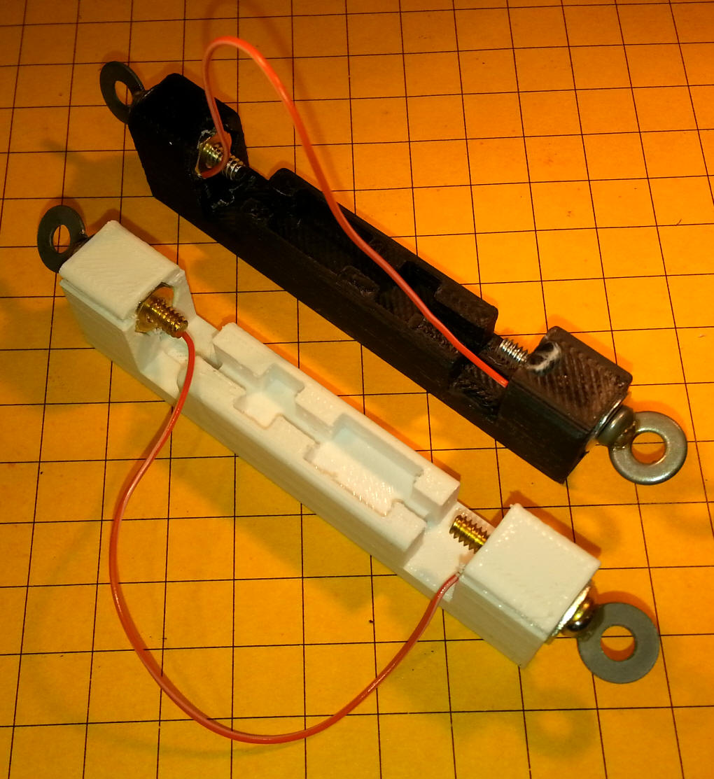
Strip a section of thin stranded hookup wire - I use
the wire that can be salvaged from old parallel printer cables. These
cables contain a bundle of individual wires and they are almost always stranded.
Although it is not necessary you can solder the wire to
the brass nuts. I find that it works just as well to place the wire behind
the nut in the hexagonal shaped hole and pull the nut against the hole and
stripped end of the wire. Test for continuity between the two screws
before cutting the wire.
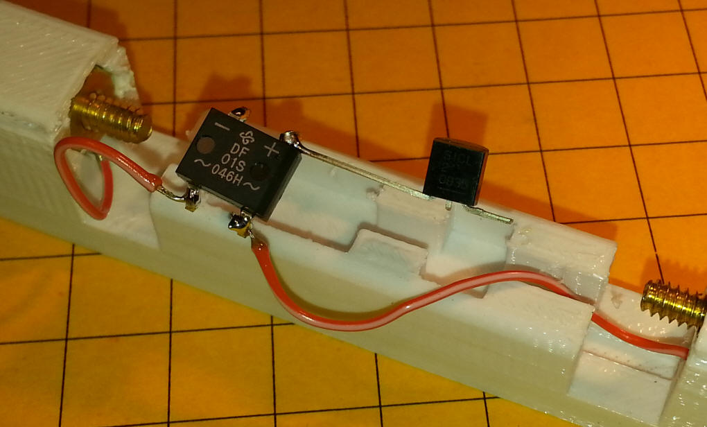
Solder the ends of each wire to the terminals on the
bridge rectifier marked with a ~ symbol. These two terminals are meant to
accept AC voltage, thus the sine wave shaped symbol.
Solder the input pin of the CL2N3 to the + terminal on
the bridge rectifier. The output pin from the CL2N3 goes to the red LED
connection wire and the black wire goes to the - terminal on the bridge
rectifier.
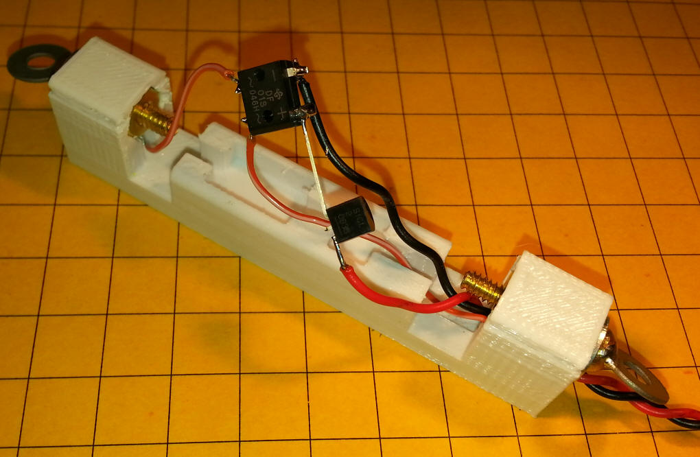
Pass the red/black wire through the small access hole.
Make sure that the wires are all pressed into the channels in the frame so that
they are protected from abrasion from the track.