|
Introduction This is easily accomplished if the train operates from standard DC track power. Unfortunately he was running either DCC or constant track power with radio control so that the polarity on the track always remains the same. The same issue would arise when using battery power. He had built a mechanism that threw a switch one way when running forward and the other way when going backwards but it put a good bit of drag on the car. He was looking for a solution that produced little or no drag. He had also considered a modification to the coupler so that a forward pull could be detected but that option was not practical with the couplers that he was using. After giving this some thought (over a few days and a few bike rides!) I came up with a method using three magnets and a reed switch. If the magnets are mounted as shown below the sequence of pulses that the reed switch produced was different based on direction of travel. |
|
| This diagram shows how the magnets are mounted
on the wheel. Three magnets are placed. Two are 60 degrees
apart and the third is 120 degrees away from the second, leaving a 180
degree gap between the third and first magnet. When the wheel turns in a clockwise direction the pulses are short, long, medium, short, long medium. When going counter clockwise they are short, medium, long, short, medium, long. By determining which pulse is the long one and comparing that to the one that follows it the direction can be figured out.
|
|
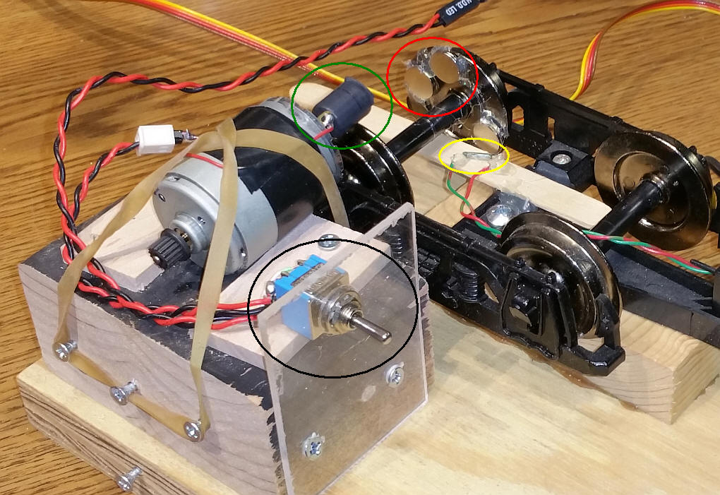
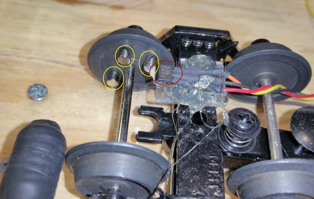
| Test Rig This mechanism was used for testing. The small motor (upper left) turns the wheel either clockwise or counter clockwise. The DPDT switch (circled in black) determines the direction or rotation. The magnets (two of the three are circled in red) pulse the reed switch (circled in yellow).
|
|
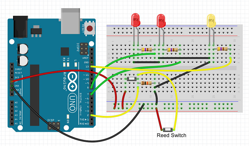
| Circuit The reed switch is mounted next to the magnets on the wheel. There is a duplicate switch on the prototype board that can be used for testing. The yellow LED lights as the wheel turns and detects magnets. One red LED lights if the wheel turns in one direction and the other red LED lights if it turns the other way. After a 5 second period without any magnet detection passes both LEDs are turned off. The diagram shows the circuit with an Arduino Uno but just about any Arduino should work. This is especially important if space is an issue.
|
|
| Software -1 Initial testing used the example program that comes with the Arduino called "Button". It simply blinks an LED when a button (or reed switch) closes. I attached one wire from the reed switch to pin 2 on the Arduino. A 10K resistor pulled that pin low by going to ground. The other wire from the reed switch connected to + 5 volts.
|
|
| Logic Analyzer Test I connected my Saleae Logic Analyzer to the output LED on the Arduino and made the following observations. Wheel clockwise rotation Note that the large period (1) has a short one (3) to the right and a medium length one to the left (2).
Wheel counter clockwise rotation
Note that the two pulse patterns are surely different. All that remains is to write a computer program for the Arduino to differentiate between them. |
|
| Software -2 The first program that I wrote measures the length of each pulse gap and sends it to the serial terminal:
|
|
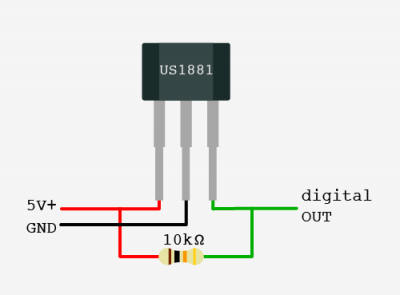
O-Scale with Hall Sensor Two adjustments to the software are needed. See notes after the photo. The first change is necessary as the Hall sensor is high when no magnet is sensed and low when a magnet is detected. The sensor's output goes to pin 2 and is pulled high with a 10K resistor. The sensor's other pins go to +5 volts and ground.
 buttonState = digitalRead(buttonPin);
  if (buttonState == LOW) {     /////////////////////////Change here for HALL
    firstMinusFlag=0;
 Serial.print("  Ratio = ");
    Serial.println(direction);
    if (direction >=2 ){    /////////////////////////Change here for HALL
      digitalWrite(ledDirection, HIGH);
      digitalWrite(ledDirection2, LOW);
|
|
|
PIC Schematic
|
|
|
PIC Basic Pro Code - version 1.0 I translated the Arduino code (written in "C") to Basic for the PIC 12F683 - The code is very similar to that of the Arduino ' d. bodnar 4-4-2015 Version 1.1
'Sample sketch to show pulses from reed switch on wheel to determine if the wheel turns CW or CCW
Include "modedefs.bas"
ansel = 0
cmcon0 = 7
Serial_out var gpio.0 'pin 7 'Serial Out
LEDPulse var gpio.2 'pin 5 hpwm 1 - Pulses when reed hit
LEDDirection1 var gpio.4 'pin 3 an3
LEDDirection2 var gpio.1 'pin 6 an1
ReedSW var gpio.5 'pin 2 - reed switch
notUsed3 var gpio.3 'pin 4
Temp1 var word
Temp2 var word
b1 var byte
b2 var byte
'Serial does not work if next line is compiled
'''OSCCON = %00100000 ' Set to 8MHz
Serout serial_out,n9600,[13,10,13,10,13,10,"d. bodnar Ver 1.1 + Wheel Direction",13,10]
Serout serial_out,n9600,[13,10,"8 MhZ 4-04-15",13,10]
gpio = %00100000 '5 is only input - others outputs
minusCount var word
firstPlusFlag var byte
firstMinusFlag var byte
countValue var word [4]
maxCountValuePosition var word
maxCountValuePosition2 var word
direction var byte
big var word
y var byte
x var byte
SerPrintFlag var bit
SerPrintFlag=0
Top:
if reedSW=1 then
firstMinusFlag =0
if (minusCount <>0) then
countValue[y]=minusCount
if (countValue[y]> big) then
big = countValue[y]
maxCountValuePosition=y
endif
y=y+1
endif
minusCount=0
high ledpulse
else
minusCount=minusCount+1
low ledpulse
endif
if y=3 then
for x=0 to 3
if SerPrintFlag=1 then Serout serial_out,n9600,[ #countValue[x]," "]
next x
if SerPrintFlag=1 then Serout serial_out,n9600,[" big= ", #big, " pos = ",#maxCountValuePosition," " ]
big =0
y=0
countValue[3]=countValue[0]
direction=countValue[maxCountValuePosition]/countValue[maxCountValuePosition+1 ]
if SerPrintFlag=1 then Serout serial_out,n9600,[" Ratio = ",#direction ,13,10]
if direction >2 then
high leddirection1
low leddirection2
else
low leddirection1
high leddirection2
endif
endif
Goto Top:
|
|
|
Two Hall Sensor Schematic
|
|
PIC BASIC PRO - uses two Hall Sensors & one magnet ' d. bodnar 4-4-2015 Version 1.3 WORKING 'Sample sketch to show pulses from reed switch on wheel to determine if the wheel turns CW or CCW Include "modedefs.bas" ansel = 0 cmcon0 = 7 Serial_out var gpio.0 'pin 7 'Serial Out LEDPulse var gpio.2 'pin 5 hpwm 1 - Pulses when reed hit LEDDirection1 var gpio.4 'pin 3 an3 LEDDirection2 var gpio.1 'pin 6 an1 Hall1 var gpio.5 'pin 2 - reed switch Hall2 var gpio.3 'pin 4 Serout serial_out,n9600,[13,10,13,10,13,10,"d. bodnar Ver 1.3 + Wheel Direction",13,10] Serout serial_out,n9600,[13,10,"8 MhZ 4-04-15",13,10] gpio = %00101000 '5 and 3 are inputs - others outputs FreeCount var word low ledDirection1:low leddirection2 FreeCount=0 Top: FreeCount=freecount + 1 if Hall1 = 0 and freecount > 5000 then Freecount=0 high LEDDirection1 low LEDdirection2 endif if Hall2 = 0 and freecount > 5000 then freecount=0 high LEDDirection2 low LEDdirection1 endif goto top:
|