Revised 10-14-09
The
receiver for Aristo-Craft’s Train Engineer Revolution has the
capability to
control six auxiliary functions that can activate sounds and turn the smoke unit
control accessory
on or
off.
These
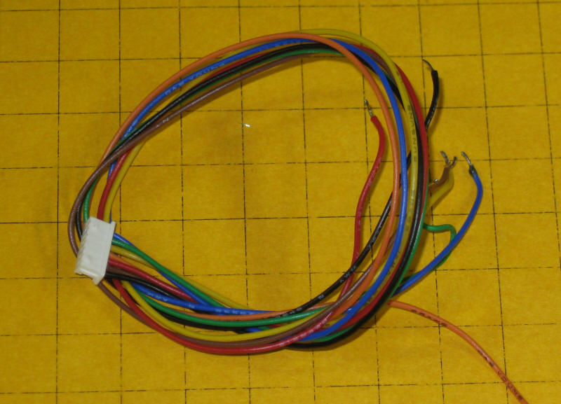
functions are activated by means of an auxiliary wiring harness that connects to
a plug on the receiver. It is
made up
of seven wires, six for control and one for ground.
The
Revolutions receiver outputs are referred to as open collector outputs. This means that electronically they are
equivalent to NPN transistors. The
control lead from the wiring harness is connected to the collector of the
transistor
whose emitter is attached to ground.
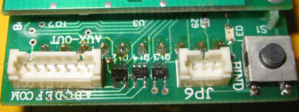
When an auxiliary output is activated on the Revolution the control lead connects whatever device it goes to to ground. This design works well but is limited by the amount of power that it can handle. The devices on the receiver are dual chip transistors, part # SUR521H. According to the data sheet each of the transistors is rated at 100 ma. I would not, however, connect a device that would draw anything near that level. It is best to keep the current draw to 20 or 30 ma, maximum.
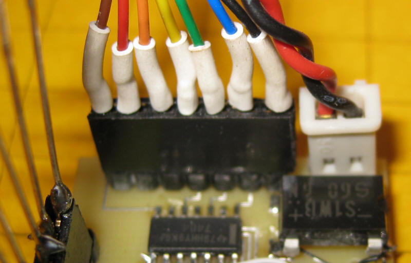
The devices are seen at the center of this photo. Note the "2X" markings on them. This was the only clue to their identity.... it was great fun getting the data sheet for them!
This
is not a problem when these leads are used to activate a small LED or horns
or bells
on a sound card but problems arise when incandescent cabin lights or
smoke
units are used as they can draw much more power.
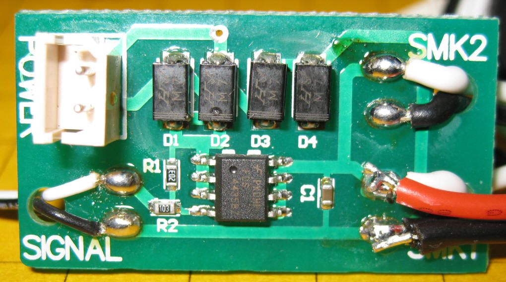
Aristo Craft has designed a smoke board that contains power transistors that can control a high current smoke unit. The smoke boards can also be used to control incandescent light bulbs and other DC loads.
The photo here shows the smoke board. The four devices at the top are diodes that accept power of either polarity. The 8 pin device at the bottom is a Mosfet that turns the power on or off based on the input signal from the receiver. It is part # FDS4435BZ.
Although the smoke board works well I felt that a more compact board that would provide buffered connections between the Revolution receiver and whatever an operator might want to control would be a better solution for me.
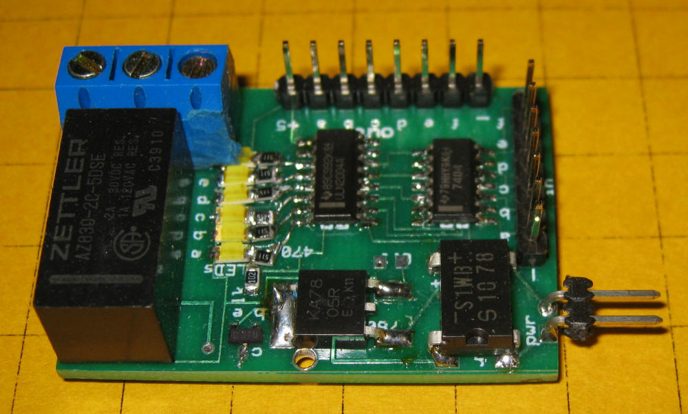
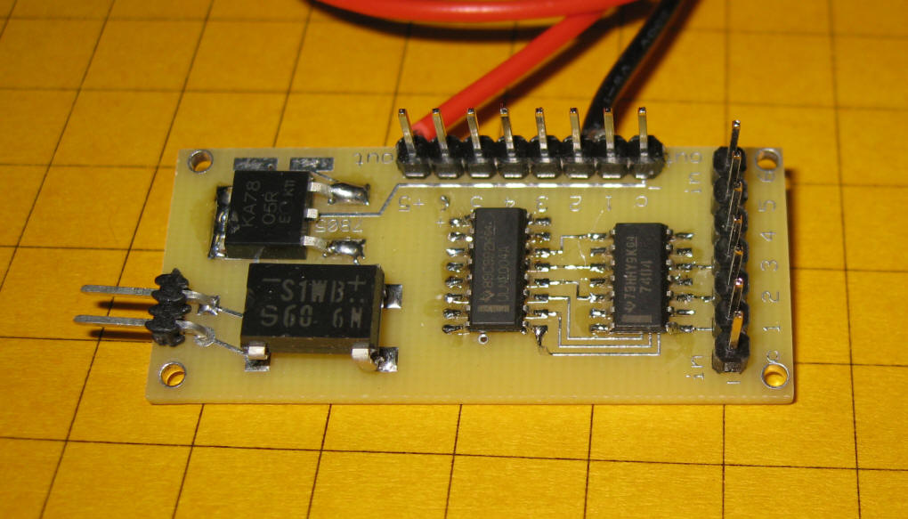
The board shown here has only a few components. There are two surface mount integrated circuits, a bridge rectifier and surface mount voltage regulator. In addition there is a DPDT relay that can be used to control devices that need an amp or more to operate.
Each output can sink 1/2 amp and can be used to control small relays or other devices. No individual device can draw more than 1/2 amp and the ULN2003A may overheat if all six outputs are simultaneously used to supply 1/2 amp. This would also overload the voltage regulator that is rated at 1 amp maximum output.
SCHEMATIC
There are two ICs in
the schematic. The 74LS04
is a hex inverter and the ULN2003A is a
Darlington transistor array. The 74LS04 takes the output from
the Revolution's auxiliary cable and inverts it before connecting its
output to the input of the ULN2003A. The Darlington array can
sink 500 mA. Its outputs go directly to the 8 pin output header
at the bottom of the drawing. The last output (#6) from the
revolution is connected to a relay. If there is no need for the
relay it can left off of the board.
Power for the auxiliary interface can be taken from the track power connections or, in the case of a battery operated locomotive, direct from the battery. In the photo below track or battery power goes into the non-plug & play board through the outside wires, colored red and black. Wires can easily be soldered to these contacts and routed to the power input terminals on the interface. Note that polarity does not matter as the interface has a bridge rectifier installed on it.
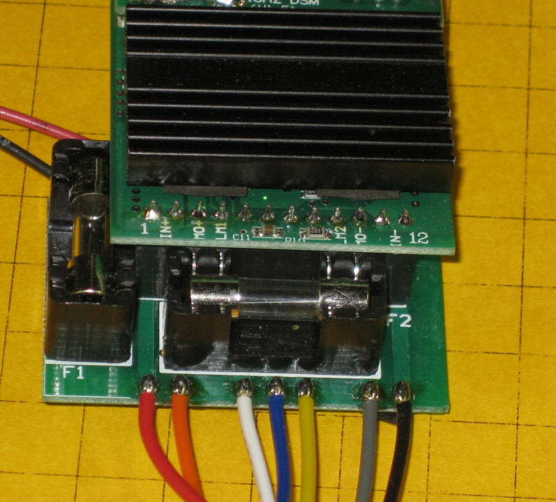
This photo shows the 7 wire auxiliary cable connected to the interface board. The black wire goes to the right and the other six follow in sequence. The red and black wires far to the right go to the track or battery power pick up connections.
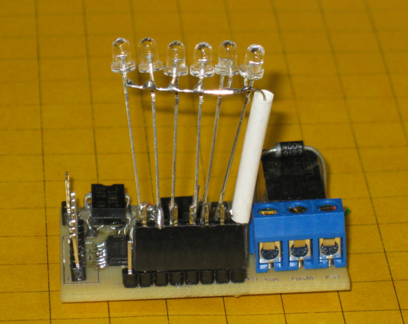
Here a set of six LEDs have been connected to the output header. Note that the left most pin is not being used - it connects to ground. The connection to the far right (with the white tubing) is +5. The anodes of all of the LEDs are wired together and connected to that pin. Each of the cathodes go to an output pin. We could easily substitute six 5 volt relays for the six LEDs.
The blue connector goes to the NO, Common, NC contacts on the relay that is controlled by pin 6.
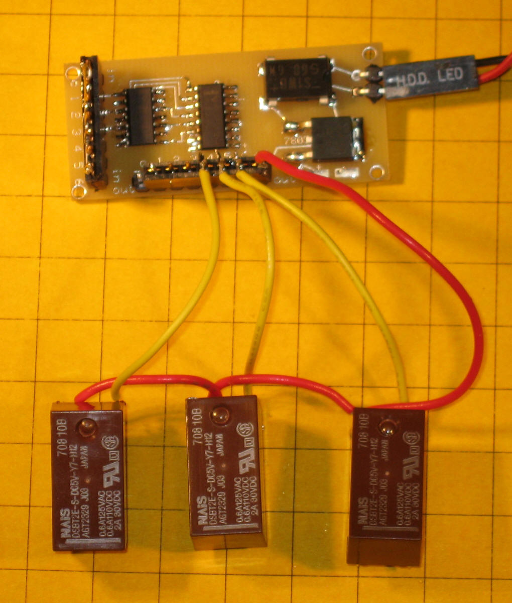
The latest revision of the board does not contain the single relay. This was done to keep the board size to a minimum. The two wires at the top connect to the coil contacts on a 5 volt DPDT relay.
The test setup shown below was used to determine the power handling capacity of the circuit when used with three 5 volt DPDT relays.
Each relay draws about 70 ma. When the circuit is supplied with 20 volts and the three relays are activated the voltage regulator quickly heats to well over 200 degrees Fahrenheit. This is because the excess voltage (between 5 and 20 volts) it turned into heat. When the supply voltage was dropped to 12 or fewer volts the temperature dropped to about 150 degrees F, a more acceptable temperature.
Note: the three relays drew a total of about 1/4 amp. The difference between 5 volts and 20 volts is 15 volts. 15 volts @ 0.25 amps is about 4 watts - no wonder it got hot!
In order to deal with these heat issues the next step is to experiment with a 12 volt version of this circuit. That will require replacing the ULN2003a with a ULN2004a, the7805 with a 7812, and the 7404 with a 4049. Such a circuit would allow one to directly drive 12 volt relays and other devices. It would also tend to heat the voltage regulator less as the difference between the supply voltage and the output voltage would be smaller.