Bike Blinker +Plus+
Revised 07-11-10
Kit Construction Step-by-Step
Parts
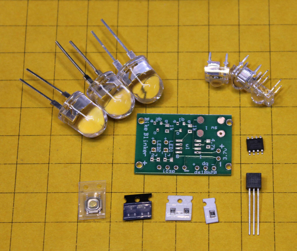
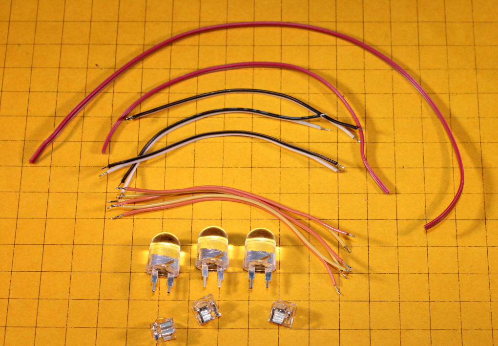
Gather the parts from the kit and the other materials that you need.
Make sure that you have properly identified each item and that you
have a clear workspace when you remove the surface mount components, especially
the resistors, as they are very easy to lose!
The parts shown above are as follows (starting in the upper left and going clockwise)
Additional Parts
In addition to the parts in the kit you will need:
two different colors of thin stranded hookup wire for power leads
three different colors of small gauge hookup wire should you want to extend the temperature sensor
soldering iron - fine tip
solder - thin
tweezers
heat shrink tubing or electrical tape
magnifying glass
wire cutters
batteries to provide between 3 and 5 volts (3 AAA rechargeable cells, for example)
2 additional resistors (50 to 100 ohms) should you supply more than 3.7 volts to the circuit
glue (hot melt works well) or double sided tape to mount the unit and LEDs to your helmet
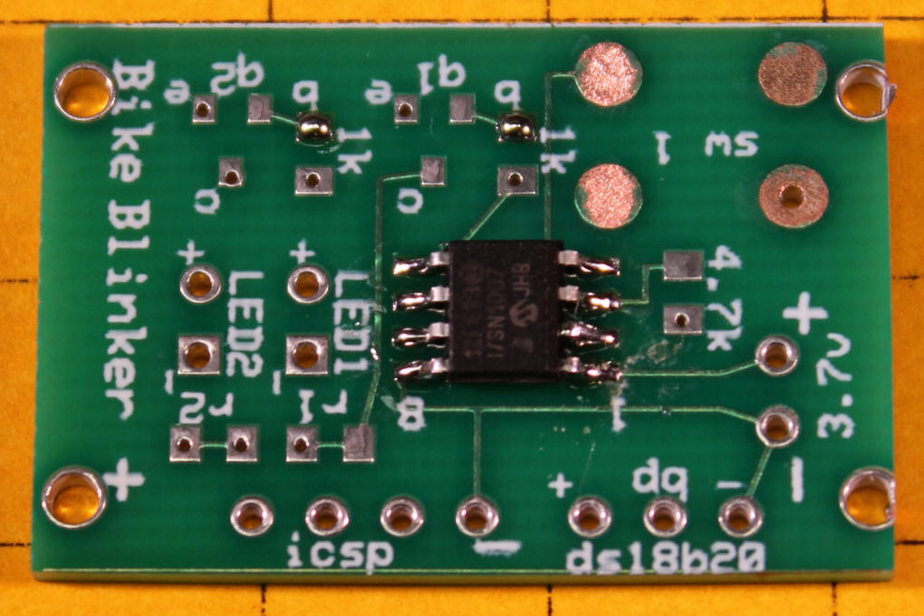
Installing the Microcontroller
Identify pin 1 on the 12F683. It is marked with a small circular
"dimple", circled in yellow in the photo below. Orient the chip so that pin 1 aligns with the number "1" on the
circuit board.
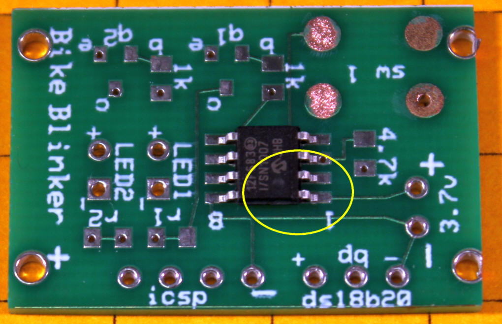
Using a fine tipped soldering iron and small diameter solder attach pin 1 of the 12F683 to the circuit board. If the chip is not soldered in place with the other pins directly over the appropriate pads reheat the solder and adjust the position of the chip as needed. After attaching pin 1 the other seven contacts on the chip must be aligned as shown in this photo. If they are angled or off center you are more likely to wind up with solder bridges when you complete soldering.
Once you are sure that the chip is aligned correctly solder the other seven pins. Use a magnifying glass to check for solder bridges between the solder pads.
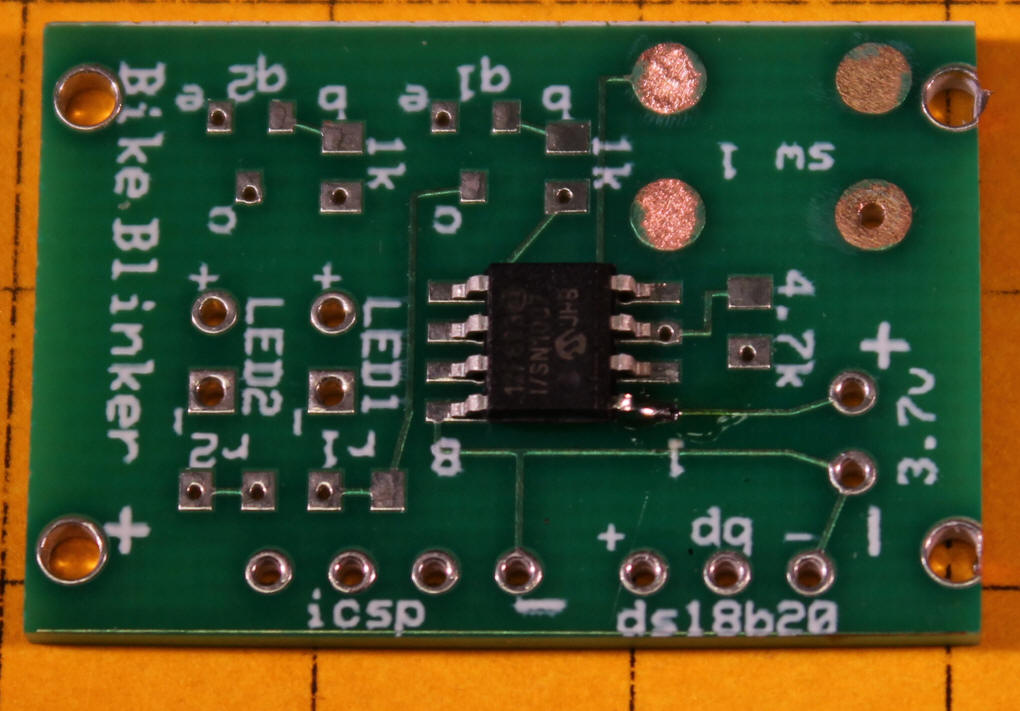
Installing the Resistors
The two 1.5K surface mount resistors each go to the side of one of the
Mosfets. The easiest way to attach them is to place a small amount of
solder onto one of the pads. They can be seen towards the top of this photo
next to the 1k labels.
Hold the resistor in place with a pair of tweezers and apply heat to the end of the resistor that is over the pad that you just tinned with solder.
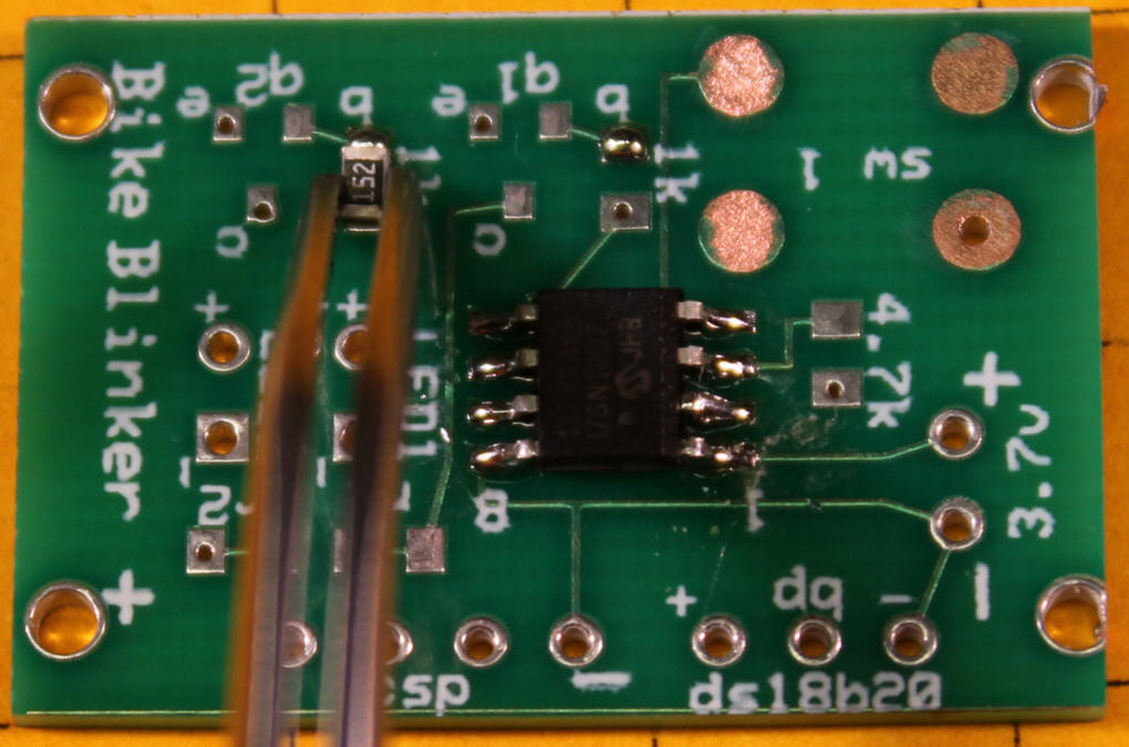
Once the solder liquefies press the resistor flat with the tweezers and allow the solder to cool. Apply heat and solder to the other end of the resistor and pad soldering that end in place.
Repeat with the other 1.5K resistor and the 4.7K resistor that is to the right of the 12F683. In the photo below the tops of the three resistors have been soldered. The bottoms will be soldered next.
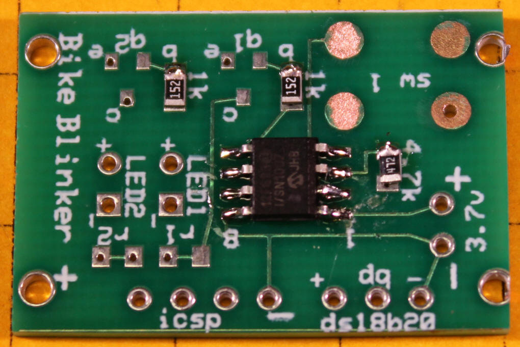
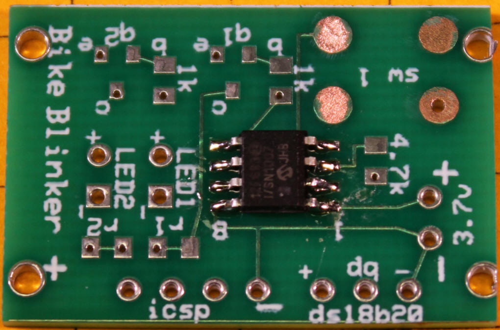
Installing the Mosfets
The two Mosfets are three terminal devices. They go to the left of
each of the 1.5K resistors. Apply a bit of solder to one of the solder
pads for each Mosfet as we did with the resistors. 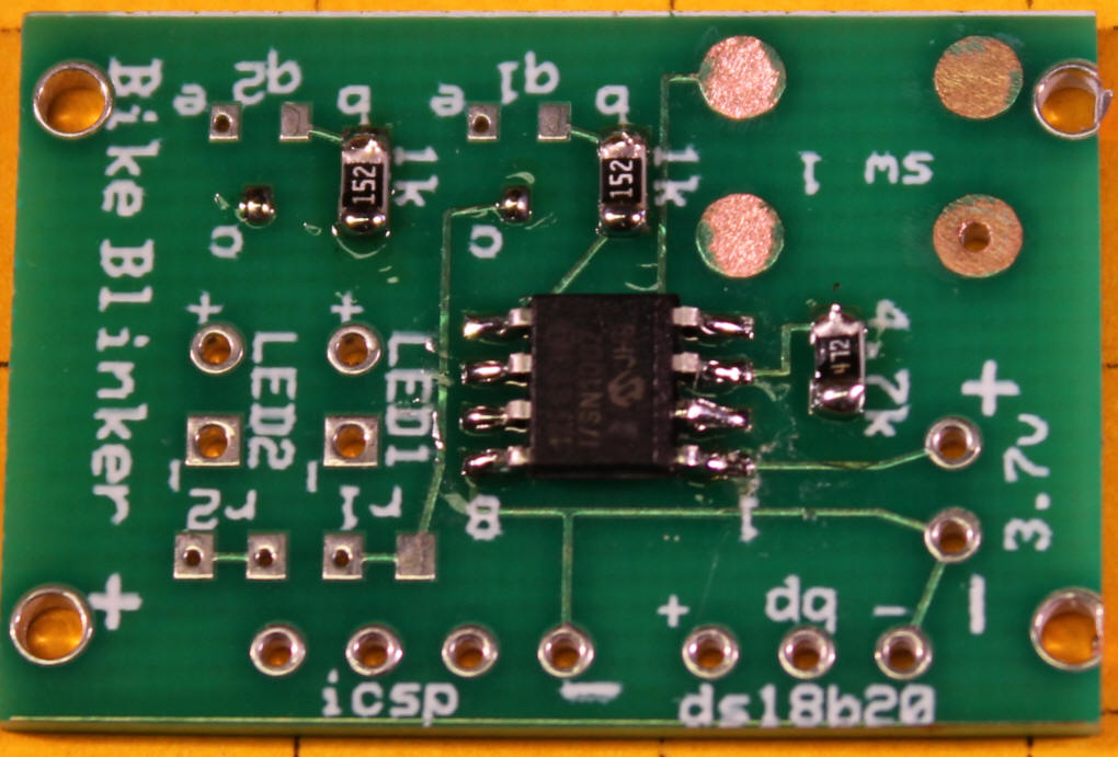
Hold the device in place with tweezers and solder that one pad. Reheat the solder and adjust the position of the Mosfets as needed. Once you are satisfied that they are aligned evenly over the solder pads use the iron and additional solder to attach the other leads.
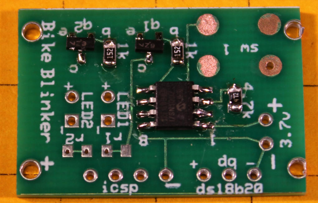
Installing the Switch
The switch has four solder tabs extending from it. It must be
oriented as shown in the photo with the tabs extending out to the sides.
Attach one tab using the same procedure employed earlier. Once the switch
is attached by one pin solder the other three. If you decide to add an
external switch (shown at the end of this document) you should attach the two
leads from it to the upper left and lower right solder pads.
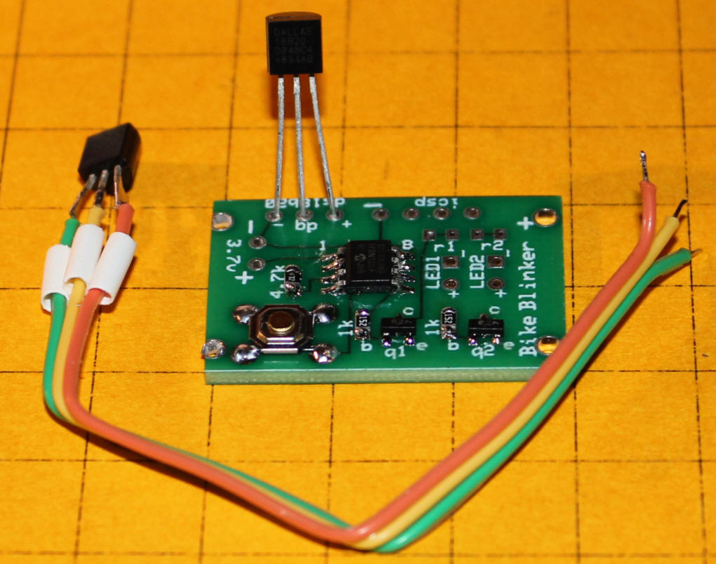
Installing the Temperature Sensor
If you are not planning on extending the leads on the temperature sensor you
can solder its leads directly to the three holes by the ds18b20 label.
Please note the orientation of the device with the flat, labeled side of the sensor
facing the 12F683.
The temperature sensor can be placed a few inches or feet from the circuit board should you need to relocate it. I put my sensor on a short length of wire to get it away from the heat radiating from my head so that winter readings would not be skewed. In the photo below the sensor is connected directly to the board. Next to it is another sensor with additional wire added to it. Note that the heat shrink tubing by the sensor still needs to be pushed against the sensor and heated so that it shrinks around the joints.
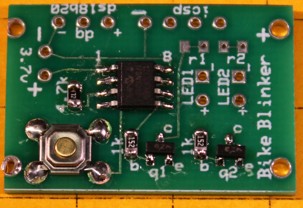
Attaching Power Leads
The wires that you use for power leads will vary depending on the way that
you supply power to the flasher. If you are wiring directly to a set of
batteries small pieces of stranded hookup wire, red for positive and black for
negative, will work well. Stranded wire is preferred as it is less likely
to break. Be very careful to wire the power leads correctly and to connect
them to the battery correctly as reversing the polarity, even for a moment, is
likely to destroy the microcontroller and the temperature sensor.
This photo also shows clearly where the LEDs will be connected, to the two pairs of holes to the right of LED1 and LED2. Note that one is marked + and one is marked -. You can also see the locations where current limiting resistors can be added if you plan on operating this unit with more than 3.7 volts. The small traces on the circuit board that connects the pads for R1 and R2 need to be cut and the resistors soldered in. This is described in more detail later on.

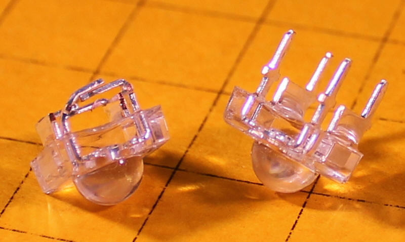
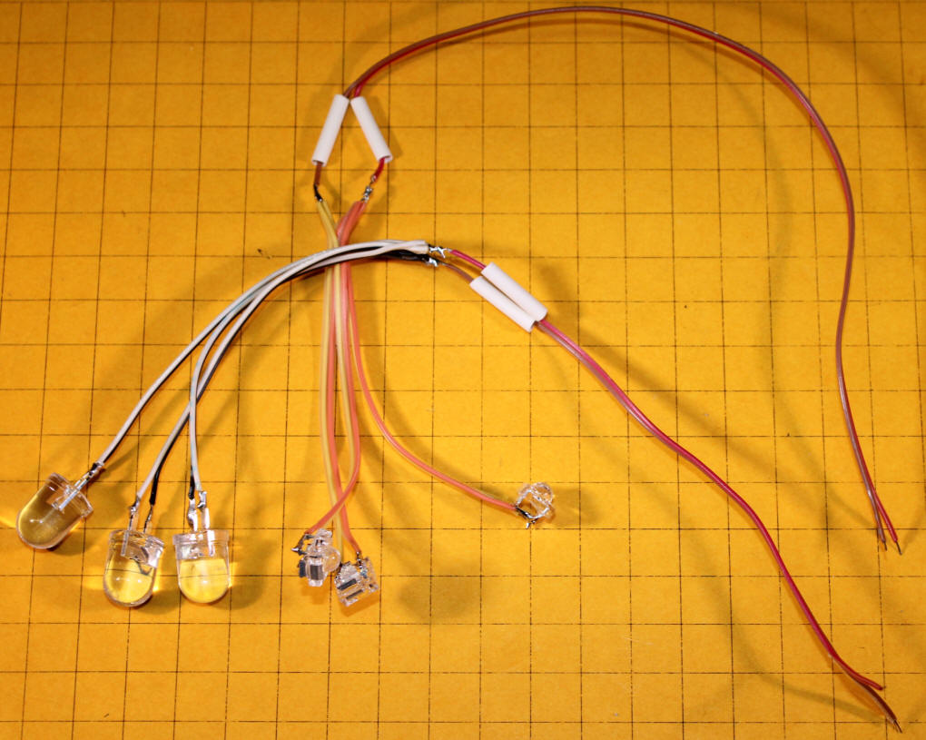
Wiring the White LEDs
The white LEDs are meant to be mounted at the front of the helmet.
There are two pairs of leads on each white LED. The two smaller leads are wired together
internally and are the positive (anode) leads. The two larger leads are
also connected together internally and are negative (cathode) leads. All three white
LEDs are to be wired in parallel. Depending on how you want to lay them
out on your helmet it may be easiest to solder two wires to each LED, one red
for positive and one black for negative, and connect them to another, longer
pair of wires that go to the circuit board. It is best to use stranded
wire for the white and red LEDs as it is less likely to break while in use.
The white LED on the left has its pairs of leads bent together to make the package a bit smaller.
Wiring the Red LEDs
The red LEDs each have two leads. The longer lead is the anode
(positive) connection and the shorter lead is the cathode (negative). Wire
them as we did the white LEDs. This photo shows all six LEDs and the
pieces of hookup wire that I used to connect them. The leads on the red
LEDs have been shortened. If you cut the leads please mark the anode
before cutting as there is no notch on the LED package to denote the cathode as
is the case with most LEDs. Before cutting down the leads I just marked
the shorter lead (cathode) with a black dot to remind me that it was the
negative lead.
Here the wiring has been completed except for placing and shrinking the heat-shrink tubing. As you can see the three red LEDs and the three white LEDs are wired in parallel.
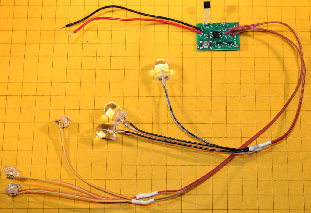
Connecting the LEDs to the Circuit Board
Once the LEDs sets have been wired together you can test them by applying 2
to 3 volts (no more!) to each set of LEDs. Once you are sure that all three red and all
three white LEDs are wired correctly you can connect them to the circuit board.
The positive lead for the white LEDs goes to one solder pad marked + and the negative lead goes to the adjoining one marked -. The red LEDs are wired to the other + and - solder pads.
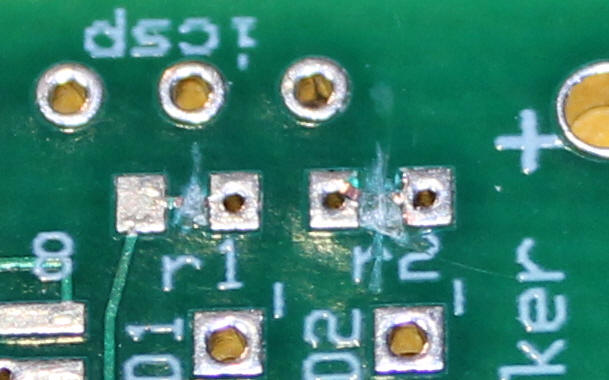
Optional Current Limiting Resistors
You will recall from the article that it is not necessary to use current
limiting resistors in series with the LEDs unless you are running the blinker from a power supply that
provides more than 3.7 volts. If you are using 5 volts, for example, you
need to cut the traces between the resistor pads and solder small current
limiting resistors, 50 to 100 ohms depending on the voltage supplied, to keep the LEDs from
drawing too much current and failing prematurely.
Here the traces between the pads labeled r1 and r2 have been cut with a razor blade. Check with an ohm meter after cutting to make sure that there is no continuity between the two pads on either side of the cuts.
If you don't have the proper value in surface mount resistors you can solder two standard 1/4 watt resistors from Radio Shack as shown here.
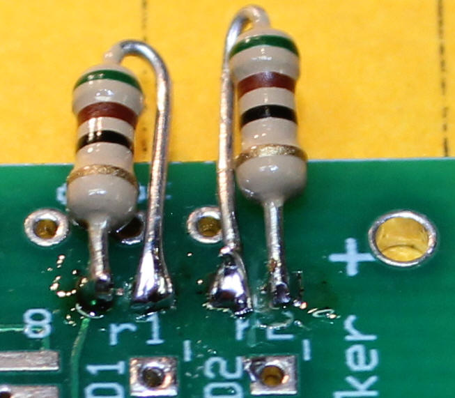
If you prefer you can also just leave the jumpers intact and wire the larger resistors shown above in series with the wires going to the two sets of LEDs.
Testing
Before connecting to power for the first time use an ohm meter to
check the resistance between the positive and negative power connections.
It should be either 0 ohms or 1 meg ohms depending on which way you hook up the
leads from the ohm meter. If the resistance is not in that range you
may have a short circuit from a solder bridge. Double check all
connections before powering up.
Once the circuit is complete and the LEDs have been installed connect the unit to your power supply. The LEDs should flash out the Morse Code letter "F" indicating Fahrenheit, then they should report the current temperature.
Try using the button to change to one of the other modes as described in the article.
Installing in your Helmet
Use hot melt or similar glue to attach the white and red LEDs to the front
and rear of your helmet. The circuit board and battery can be attached
with double sided foam tape. In this photo the three red LEDs are grouped
together at the rear of the helmet.
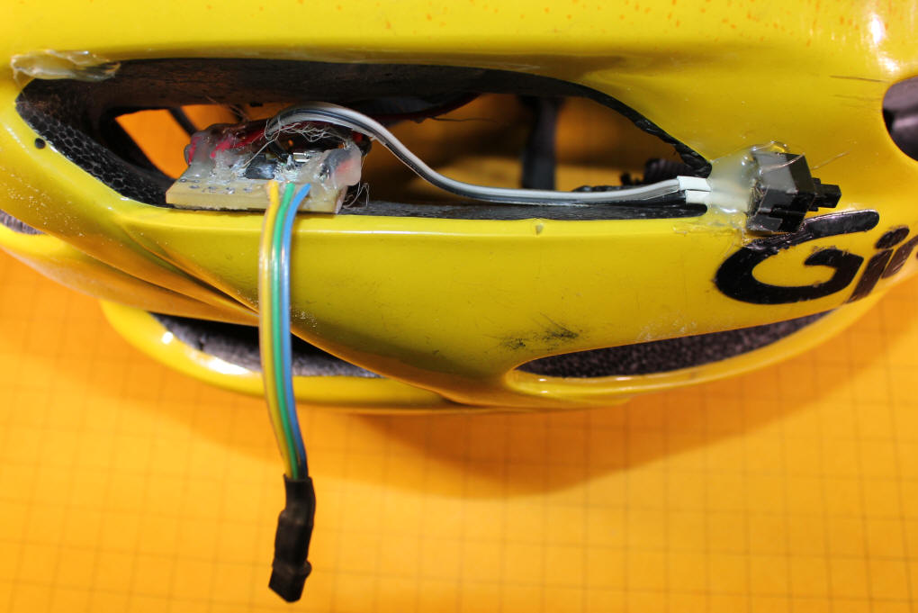
The circuit board has been mounted in one of the helmet's vents. This photo also shows the extended sensor wire and an extension push button switch that can be used to change modes. If you want to add a 2nd switch just wire it in parallel with the existing switch using two solder pads that are diagonally oriented to each other. These are shown in an earlier photo.
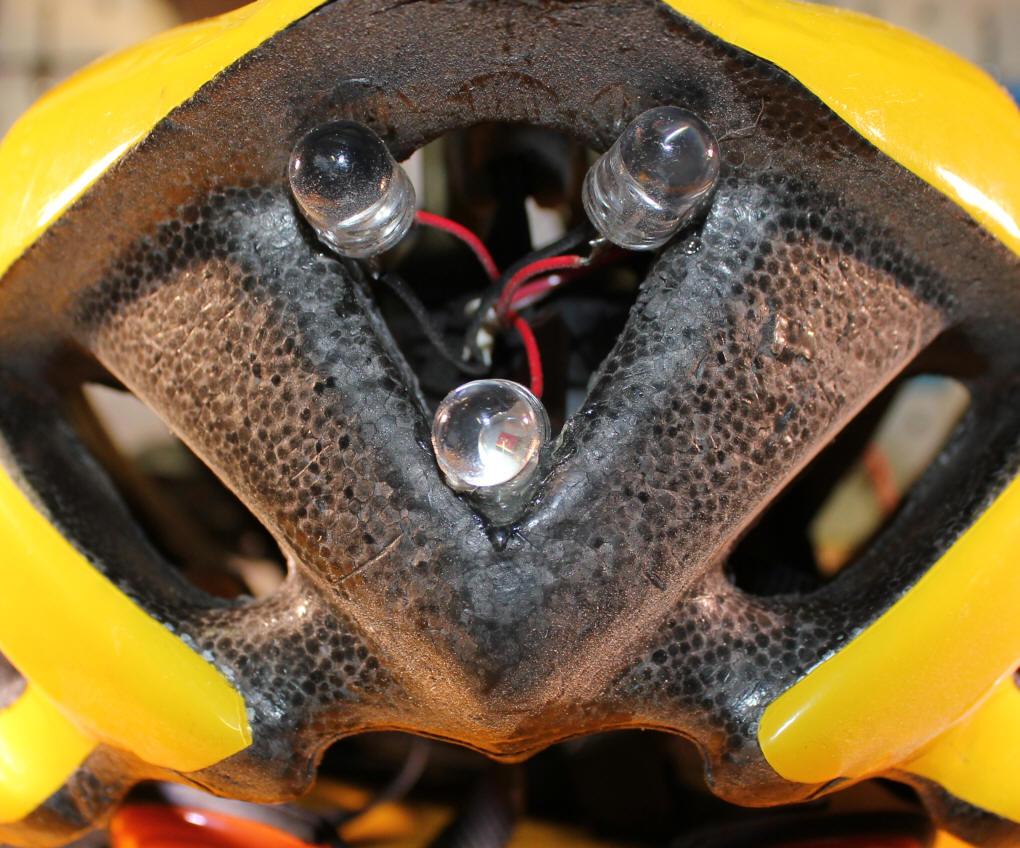
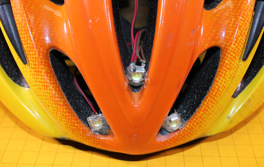
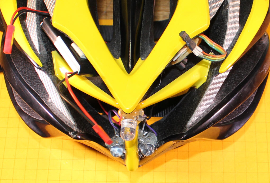
Here are three LEDs at the front of a helmet.
Here is the rear of another helmet. Note the small 3.7 volt lithium battery in a vent to the left and the circuit board & sensor to the right.
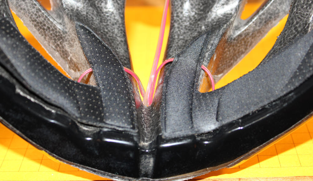
Inside of the helmet connecting wires were run under padding.
I hope that this step-by-step guide helps you to successfully assemble your Bike Blinker +Plus+ and that it gives you many, many miles and many, many years of safe cycling!