Bike Blinker +Plus+ in the Garden
revised 08-11-10

I hope you have had a chance to read the article in Nuts & Volts that describes how I made a bicycle helmet light that does double duty.  Its most important task is to alert drivers to my presence on the road but it also flashes out the temperature so that I and those riding with me know why we feel so darn cold or warm, depending on the season!

After I completed the first few helmet blinkers friends asked if I could make them blinkers with some different characteristics & capabilities. 

First I was asked to make a unit that could put into a garden so that a glance out of the window and a quick observation of the flashing LED would give an outside temperature reading.  I thought it was a great idea but a number of questions came up including:

That got me to thinking and to setting a number of design objectives.

  1. The light should be battery powered with an option to recharge the battery with a small solar panel.
  2. PIC microcontrollers have a low power "sleep" mode that would be used to make the most of whatever power we provided.
  3. The temperature would be reported every 8-10 seconds.  That would preserve the batteries and still not force you to wait very long before getting a report.
  4. A single 3mm LED should be sufficient for temperature reports.  A low operating voltage and a fairly large current limiting resistor should be used to keep the power draw to a minimum and to keep the brightness down.

The second request was for a version of the Bike Blinker that would only give a temperature report only when its button was pressed.  This was to be mounted on the handlebars of a bicycle so that a temperature report could be generated whenever it was safe to observe the blinking LED for a few seconds. 

I decided to power this unit with a small 2032 watch battery as it would be drawing nearly no power when waiting for the button to be pressed.  This would be accomplished by putting the microcontroller to "sleep" and using an interrupt, from the unit's button, to awaken it from its low power mode.

Garden Temperature Flasher
No hardware changes were needed to convert the helmet blinker to one that would reside in the garden.  I simply connected the circuit to a pair of AA cells.  Two fresh alkaline AA cells provide enough power (approximately 1000 ma / hour) to operate the blinker for more than a month.  If a smaller unit is needed AAA cells can be used.  Just remember to keep the voltage below 3.7 volts unless you install the optional current limiting resistors to protect the LEDs.

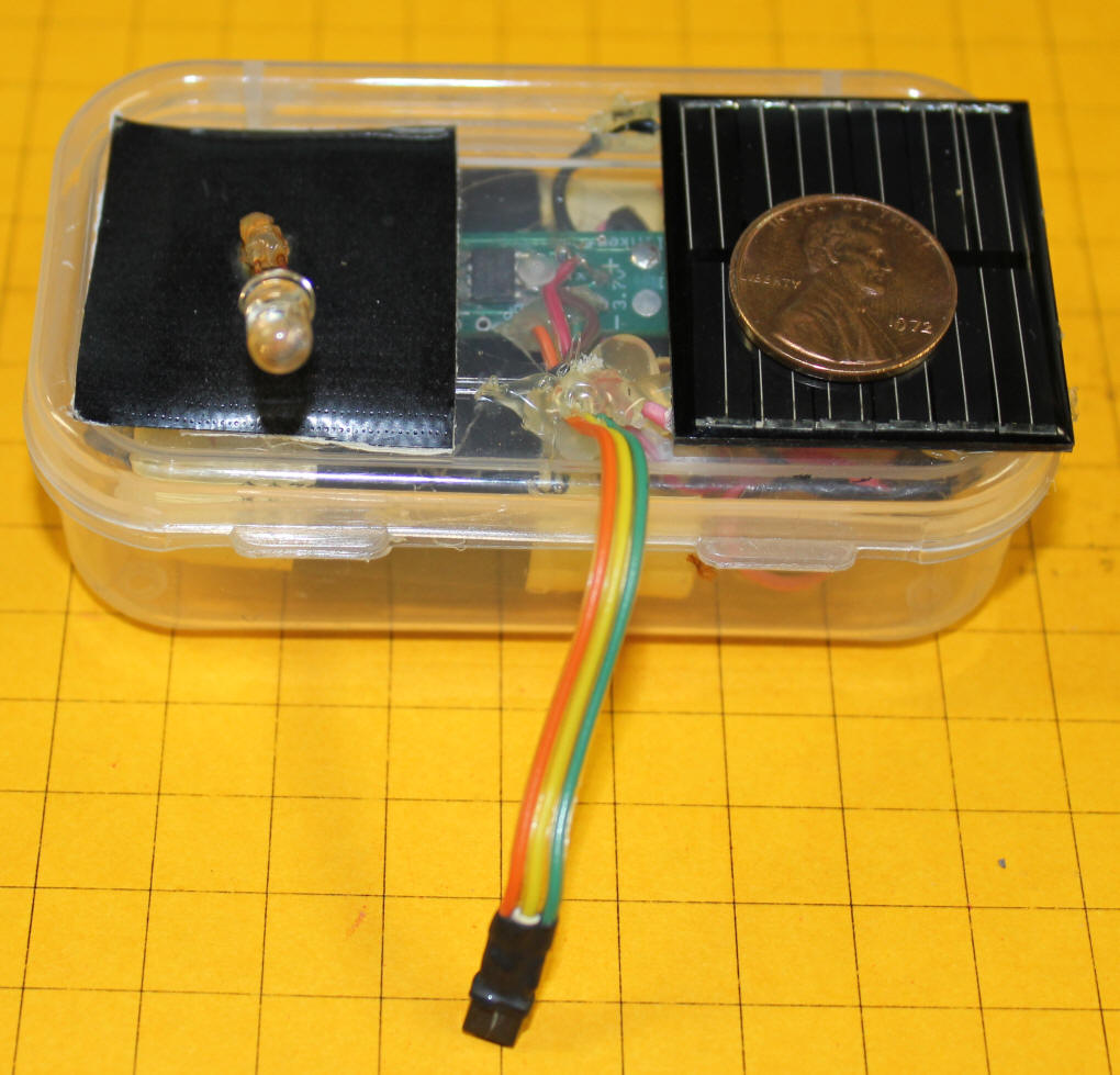
I also experimented with rechargeable batteries that were charged during the day with a solar panel.  I found very small solar cells at  Solarbotics.com that were rated for 6.7 volts at 31ma.  I connected that solar cell to 3 AA NiCad cells and then to the flasher circuit.  Even though the solar cell was extremely small, less than 1.5" square, it did a great job of keeping the unit alive. 

In this photo the solar panel is on the right with a penny sitting on it.  The LED is on the left.  The piece of black tape behind the LED helps with viewing when the unit is in sunlight.  The circuitry and 3 AA NiCad cells are in the small plastic box.  If you look carefully you may be able to see that the LED's leads have begun to rust.  That is the only sign of corrosion that I have noted to date.

The tests with solar charging were done in the summer and I suspected that a larger solar panel may be needed in the winter due to the shorter days and a dearth of sunlight.

I found a likely candidate for a larger solar panel from BG Micro.  They sell a solar unit that is a larger (2 3/8" square) and delivers 4.5 volts at 90 ma.  It, too, worked well in the summer and I expect it will keep the blinker working through those long dark winter days!

The schematic is about as simple as it gets!  The solar panel is to the left and the batteries are to the right.  Diode, D1, keeps the batteries from discharging through the solar panel at night when the sun is down.  Just make sure that you don't run the blinker without the batteries in the circuit.  In direct sunlight many solar panels can put out sufficient voltage to destroy the microcontroller.  The batteries in the circuit provide a load that helps to keep the voltage down.  Even though the schematic shows 2.4 volts for the batteries (two rechargeable cells) it works equally with three or four cells.  Just make sure that the output from the solar panels is a few volts above the voltage of the battery.

Batteries
If you decide to use the solar powered option you can use either NiCad or NiMh rechargeable cells.  NiCads give more charge / discharge cycles while NiMh 
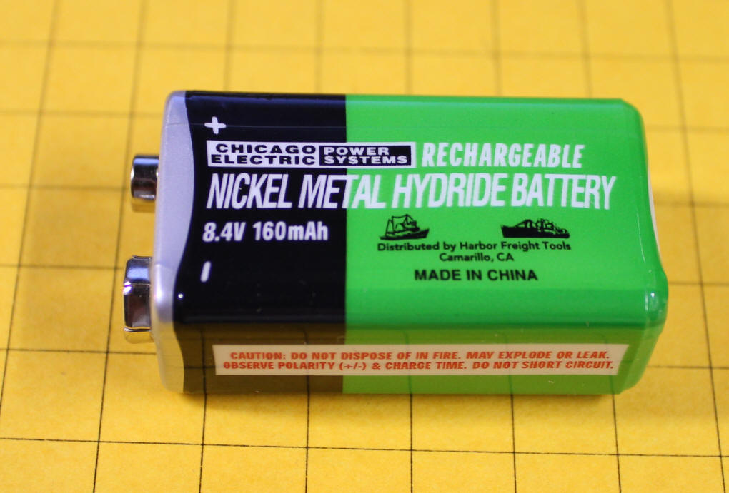
typically have a higher mAh rating.  I decided to use some very small NiMh cells from Harbor Freight.  Each cell is only about 1 cm in diameter and 1.5 cm high.  You won't find these tiny cells in their catalog as they are hidden within their 9v rechargeable battery, shown here.  Note that the 9 volt battery is marked 8.4 volts.  Since one NiMh cell puts out 1.2 volts I reasoned that there should be 7 individual cells inside.  Little did I know how nicely they would work out for this project.

To disassemble the battery remove the colored label material and pry off the top.  You should then be able to slide the insides of the unit out of the case.  As you can see there are seven individual cells wired in series. 

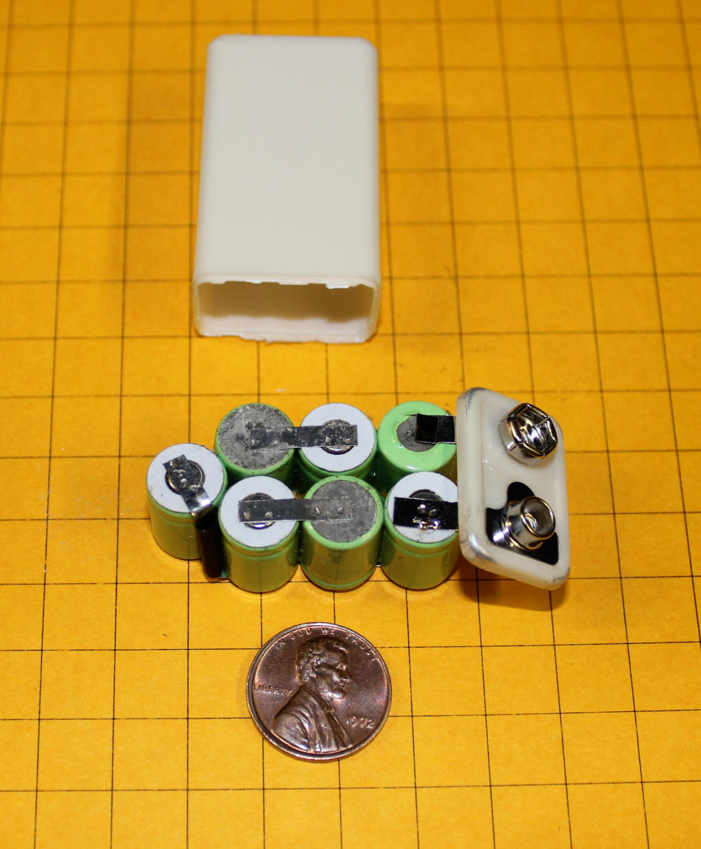
I first experimented with using three of the cells (shown here) and encasing them in heat shrink tubing.  It worked fairly well but I decided to use four cells to get a bit more brightness from the LEDs.

The solar panels from BG Micro ( http://www.bgmicro.com/pwr1241.aspx ) are shown here.  Each panel puts out 4.5 volts in direct sunlight.  That is a bit lean to recharge four cells so I opted to put two panels in series giving me an output of about 9 volts.  This drops a bit due to the diode that is in series with them but is more than sufficient to charge four cells.

It is important to note that there is a black "-" sign that has been placed on the back of each panel indicating the negative lead.  Here are the two panels ready to be wired in series.

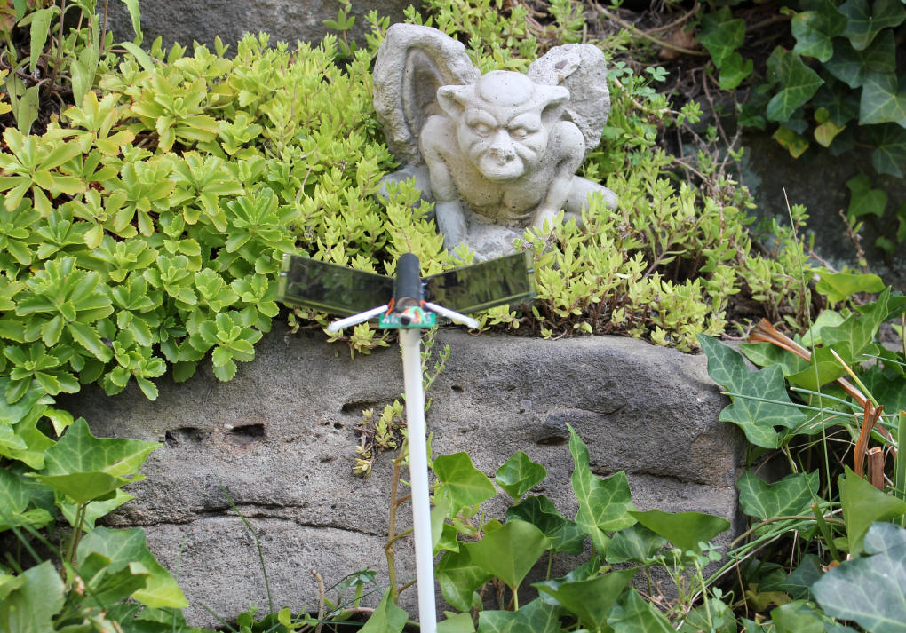
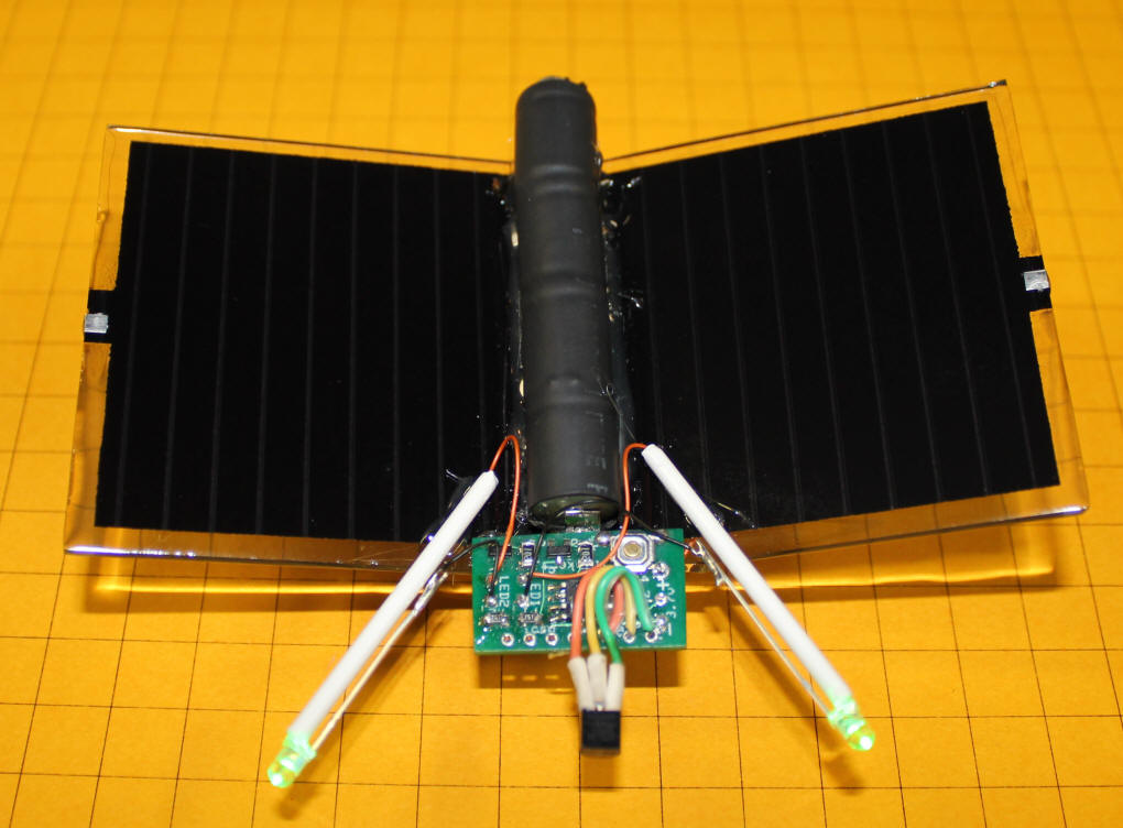
When joined together at a slight angle as shown here the panels began to resemble butterfly wings so I glued the battery, encased in black heat shrink tubing. in the center to represent the insect's body. 

The circuit board and two pieces of plastic tubing were added.  The tubing holds the two LEDs that blink out the temperature and resemble a butterfly's antennae.  The temperature sensor is in the center on a short wire extension.  Note that in this photo I am using four cells wired in series.

The unit is nearly complete with its green LEDs lighting up brightly as they flash out the temperature.

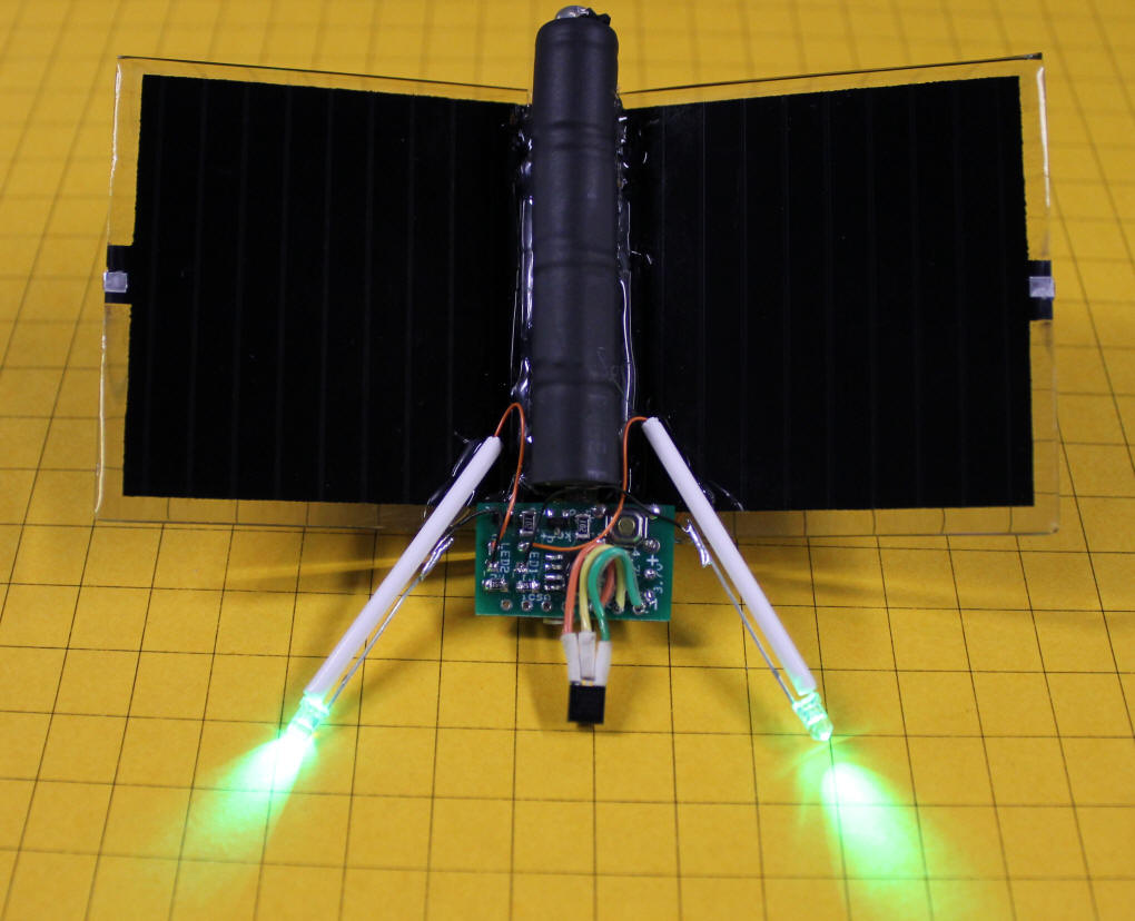
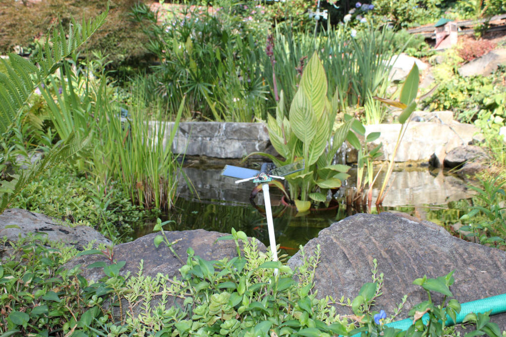
A short stick attached to the bottom allows for easy placement in the garden.

Software Changes
The software modifications for the garden flasher are very minor.  The processor is put to sleep for 7 seconds after each temperature report.  The area of the program where changes were made are highlighted
in RED in the listing below.

The mode selection routines are bypassed and the unit only works as a temperature reporter.  The button has one purpose.  You can hold it in on power-up to change the temperature from Fahrenheit to Celsius or visa versa.

GARDEN FLASHER
'd. bodnar 12-26-09 0 fixed error between 15 and 8 F
'Modified 03-02-10 to only give temperature when button pushed - no other functions
'Modified 06-26-10 to give temperature every 10 seconds - sleeps in between
'Modified 8-11-10 to allow button on power up to change temperature scale (f/c)
'1998 bytes of 2048 before text strings removed
'THIS WORKS: serout2 serialout, 84+16384,[bin r_temp,10,13] '84=9600- 16384=inverted data
INCLUDE "modedefs.bas"
ansel=0                 'use pins as digital rather than analog
DEFINE OSC 8            'use 8 mhz oscillator
OSCCON = $70            'set clock speed 
option_reg.7=0          'turn on weak pull ups
wpu = %00100000         'weak pull ups on pin GPIO.5 only 
INTCON = %00001100      '00xx11xx to be CCP1 mode

SerialOut       VAR GPIO.0      'pin 7
NotUsed1        VAR GPIO.1      'pin 6
LED             VAR GPIO.2      'pin 5 
NotUsed3        VAR GPIO.3      'pin 4
DQ              VAR	GPIO.4      'pin 3 One-wire Data-Pin "DQ"
ChangeSwitch    VAR GPIO.5      'pin 2
R_Temp          VAR	WORD        'RAW Temperature readings
C_Temp          VAR WORD        'Celsius Temperature
Decimal_C_Temp  VAR WORD        'store just the decimal C temperature
F_Temp          VAR WORD        'Fahrenheit Temperature
G_Temp          VAR WORD        'Generic Temperature for report (either C or F)
NEGPOS          VAR BYTE        'Sign char "-" or "+"
C               VAR BYTE        'Status of I/O port bit
Minimum         VAR BYTE        'minimum temperature (store as C or F)
Maximum         VAR BYTE        'maximum temperature (store as C or F)
Mode            VAR BYTE        'branch variable
Y               VAR BYTE        'for/next variable
Z               VAR BYTE        'temporary variable
Ones            VAR BYTE        'ones
Tens            VAR BYTE        'tens
Hundreds        VAR BYTE        'hundreds
Scale           VAR BIT         '=0 if Fahrenheit / =1 if Celsius
SleepCounter    VAR BYTE        'count times mode shown before sleep
C_neg           VAR BIT         '=1 if cold bit for C set
MinMaxReptFlag  VAR BYTE        '0=temp, 1=min, 2=max- order of minmaxreport

TPause          CON 300
BetweenPause    CON 300
Mode            = 1             'start in Temperature reporting mode
Scale           = 0             '0 =  Fahrenheit
GPIO            = %00110000     'GPIO 4 & 5 as inputs - others as outputs
DATA @0,0,0                     'start with Fahrenheit scale (0) & mode 0
READ 0, Scale                   'read saved scale (F or C)   
READ 1, Mode                    'read mode 

SEROUT SerialOut,n9600,[12,10,13,"Ver 5.1T Bike Blinker +PLUS+ Time ONLY!!",10,13]
SEROUT SerialOut,n9600,["(c) d. bodnar 08-11-10",10,13]
 
VeryTop:  
LOW LED 
'''pause 1000
MinMaxReptFlag=0
'gosub showscale                 'flash "C" or "F" in Morse Code
'Note that minimum & Maximum are stored as temperature + 100 to handle negatives
Minimum         = 255           'store as temp + 100 , below 100 is negative
Maximum         = 0             'gives range of 100 below to 125 above

IF ChangeSwitch = 0 THEN        'if switch held change scale
    Scale = NOT(Scale)
    GOSUB ShowScale
    WRITE 0,Scale               'save current scale to memory
    WHILE ChangeSwitch=0        'stay here till switch released
        GOSUB showscale
    WEND
ENDIF   

start:
GOTO Temperature
Start2:
GOTO gotosleep:
'if changeswitch=0 then goto ChangeMode
'Branch  Mode, [Temperature, FullBrightFast, FullBrightSlow, FullOn, MinMaxReport]
GOTO start:

Temperature:
GOSUB Start_Convert
'serout serialout,n9600,[10,13,"-+= ",negpos,10,13 ]
IF Scale = 1 THEN 
    G_Temp=C_Temp        '0=fahrenheit, 1=celsius
    ELSE
    G_Temp=F_Temp
ENDIF

Report_Temperature:
IF NEGPOS = "+" THEN
    IF G_Temp + 100 > Maximum THEN    'save new max if new temperature is above old
        Maximum = G_Temp+100
    ENDIF
    ELSE
    IF 100-G_Temp  > Maximum THEN
        Maximum = 100-G_Temp
    ENDIF
ENDIF

IF NEGPOS="+" THEN
    IF G_Temp + 100 < Minimum THEN    'store new minimum temperature if lower
        Minimum = G_Temp+100
    ENDIF
ENDIF
IF NEGPOS="-" THEN
    IF 100-G_Temp< Minimum THEN
        Minimum=100-G_Temp
    ENDIF
ENDIF
SEROUT SerialOut,n9600,["Min/Max = ",#Minimum," ",#Maximum,10,13,10]
HIGH LED:FOR Y=1 TO 20:TOGGLE LED:PAUSE 20:NEXT Y:LOW LED  'fast blink @ start
IF C_neg = 1 AND Scale=1 THEN ' temperature is below zero Ceisius
    NEGPOS = "-"
ENDIF
IF (Scale=0 AND NEGPOS = "-") OR (C_neg=1 AND Scale=1)  THEN 'dim LED after rapid flash to show below zero temperature
    GOSUB minpwm:
ENDIF
IF ChangeSwitch=0 THEN GOTO ChangeMode 'watch for button press
PAUSE 400
'serout serialout,n9600,["G=",#G_Temp," +- ",NEGPOS,10,13]     'sign is for celsius!
Hundreds=G_Temp/100
'serout serialout,n9600,["Gh=",#G_Temp," ",#hundreds,10,13] 
IF Hundreds<>0 THEN ' show hundreds of degrees if temperature is >=100
    FOR Y=1 TO Hundreds:HIGH LED:PAUSE TPause:LOW LED:PAUSE TPause
    IF ChangeSwitch=0 THEN GOTO ChangeMode  'watch for button press
    NEXT Y
    PAUSE BetweenPause:PAUSE BetweenPause
ENDIF
IF ChangeSwitch=0 THEN GOTO ChangeMode     'watch for button press
G_Temp=G_Temp-(Hundreds*100)
Tens=G_Temp/10
'   serout serialout,n9600,["Gt=",#G_Temp," ",#Tens,10,13] 
IF Tens<>0 THEN ' show tens of degrees
    FOR Y=1 TO Tens:HIGH LED:PAUSE TPause:LOW LED:PAUSE TPause
    IF ChangeSwitch=0 THEN GOTO ChangeMode   'watch for button press
    NEXT Y :PAUSE BetweenPause
    PAUSE BetweenPause
ELSE 
    HIGH LED:PAUSE 40:LOW LED:PAUSE 40:PAUSE BetweenPause
    PAUSE BetweenPause
ENDIF
IF ChangeSwitch=0 THEN GOTO ChangeMode  'watch for button press
G_Temp=G_Temp-(Tens*10)
Ones=G_Temp
'serout serialout,n9600,["Go=",#G_Temp," ",#ones,10,13] 
IF Ones<>0 THEN ' show ones of degrees
FOR Y=1 TO Ones:HIGH LED:PAUSE TPause:LOW LED:PAUSE TPause
IF ChangeSwitch=0 THEN GOTO ChangeMode   'watch for button press
NEXT Y:PAUSE BetweenPause
IF ChangeSwitch=0 THEN GOTO ChangeMode  'watch for button press
PAUSE BetweenPause
ELSE 
IF ChangeSwitch=0 THEN GOTO ChangeMode     'watch for button press
HIGH LED:PAUSE 40:LOW LED:PAUSE 40:PAUSE BetweenPause
ENDIF
GOTO Start2
 
Start_Convert:
OWOUT DQ, 1, [$CC,$44]		  'Send calculate temperature command
REPEAT                      
    PAUSEUS 25 	  	     	  'Waiting loop until reading complete
    OWIN DQ, 4, [C]			  'Monitor for pin high transition ...   
UNTIL C <> 0 				  ' ... reading complete
OWOUT DQ, 1, [$CC, $BE]		  'Send read scratchpad command
OWIN DQ, 2, [R_Temp.LowByte,R_Temp.HighByte]	'get temperature
IF R_Temp.11 = 1 THEN          'check below zero bit
    C_neg=1
    NEGPOS = "-"
    R_Temp = ~R_Temp + 1
ELSE 
    NEGPOS = "+"
    C_neg=0
ENDIF
C_Temp = R_Temp >> 3        'Get whole # of degrees & first decimal bit
SEROUT SerialOut , n9600,["C =  ",NEGPOS,#C_Temp/2," deg. C",10,13]
F_Temp = C_Temp * 9  
F_Temp = F_Temp / 5
F_Temp=F_Temp/2 	     'remove decimal bit
IF NEGPOS="+" THEN
    F_Temp = F_Temp + 32 
ENDIF
IF NEGPOS ="-" AND C_Temp <= 36 THEN    'was 18 - caused error!
    F_Temp = 32 - F_Temp 
    NEGPOS = "+"
ENDIF
IF NEGPOS="-" AND C_Temp > 36 THEN      'was 18 - caused error!
    F_Temp = F_Temp  - 32
ENDIF
SEROUT SerialOut,n9600,["F =  ",NEGPOS,#F_Temp," deg.F",10,13]
C_Temp = C_Temp/2	
RETURN

FullBrightFast: 'full brightness - fast blink
SEROUT SerialOut,n9600,["@f",10,13] 
HIGH LED:PAUSE 60:LOW LED:PAUSE 60:GOTO start:

FullBrightSlow: 'full brightness - slow blink
SEROUT SerialOut,n9600,["@s",10,13] 
HIGH LED:PAUSE 500:LOW LED:PAUSE 500:GOTO start:

FullOn:
SEROUT 0,n9600,[10,13,"@ON",10,13]
HIGH LED
GOTO start:


ShowScale:
DIT CON 70        'Morse Code DIT
DAH CON DIT*3     'Morse Code DAH
SPACE CON DIT*5   'Morse Code space between Dits & Dahs
''serout serialout,n9600,["Sc=",#scale,10,13]

IF Scale=0 THEN    'Morse Code "F"
    HIGH LED:PAUSE DIT:LOW LED:PAUSE SPACE:HIGH LED:PAUSE DIT:LOW LED:PAUSE SPACE
    HIGH LED:PAUSE DAH:LOW LED:PAUSE SPACE:HIGH LED:PAUSE DIT:LOW LED:PAUSE SPACE
ELSE                'Morse Code "C"
    HIGH LED:PAUSE DAH:LOW LED:PAUSE SPACE:HIGH LED:PAUSE DIT:LOW LED:PAUSE SPACE
    HIGH LED:PAUSE DAH:LOW LED:PAUSE SPACE:HIGH LED:PAUSE DIT:LOW LED:PAUSE SPACE
ENDIF
PAUSE 1000
RETURN

MinPWM:
FOR Y= 255 TO 0 STEP -1
    PWM 2, Y, 3
    IF ChangeSwitch=0 THEN GOTO ChangeMode   'watch for button press
NEXT Y
RETURN

MaxPWM:
FOR Y= 0 TO 255 
    PWM 2, Y, 3                              
    IF ChangeSwitch=0 THEN GOTO ChangeMode  'watch for button press
NEXT Y
RETURN

GoToSleep:
Mode=Mode-1
WRITE 0, Scale      'save current scale 
WRITE 1, Mode       'save current mode
SEROUT 0,n9600,[10,13,"@Sleep",10,13]
PAUSE 300
FOR Y= 255 TO 0 STEP -1  'dim showing going to sleep
    PWM 2, Y,3
NEXT Y
LOW LED:
INTCON.0 = 0	'Reset the  Port change bit 
IOC=0
LongSleep:
SEROUT 0, n9600, ["Z", 10,13]
'Pause 3000
INTCON.0 = 0	'Reset the  Port change bit
gpio.5=0        'reset switch pin
IOC = %00100000 'enable INTERRUPT ON CHANGE on gpio 5 
SLEEP 7     'pause low power 7 seconds
'if intcon.0=0 then goto longsleep
INTCON.0 = 0	'Reset the  Port change bit   
IOC=0
FOR Y= 0 TO 255  'brighten LED to show waking up
    PWM 2, Y,3
NEXT Y    
SEROUT 0, n9600, ["xZ", 10,13] 
INTCON.0 = 0	'Reset the  Port change bit   
'''pause 500
GOTO VeryTop:

ChangeMode:
RETURN
 

On Demand Temperature Flasher
The unit that was to be mounted on the bicycle's handlebars was modified to sit on top of a battery holder for a 2032 lithium battery.  Even though these cells are very small and can only deliver a small amount of power the fact that the processor is in an extremely low power mode when not flashing allows a 
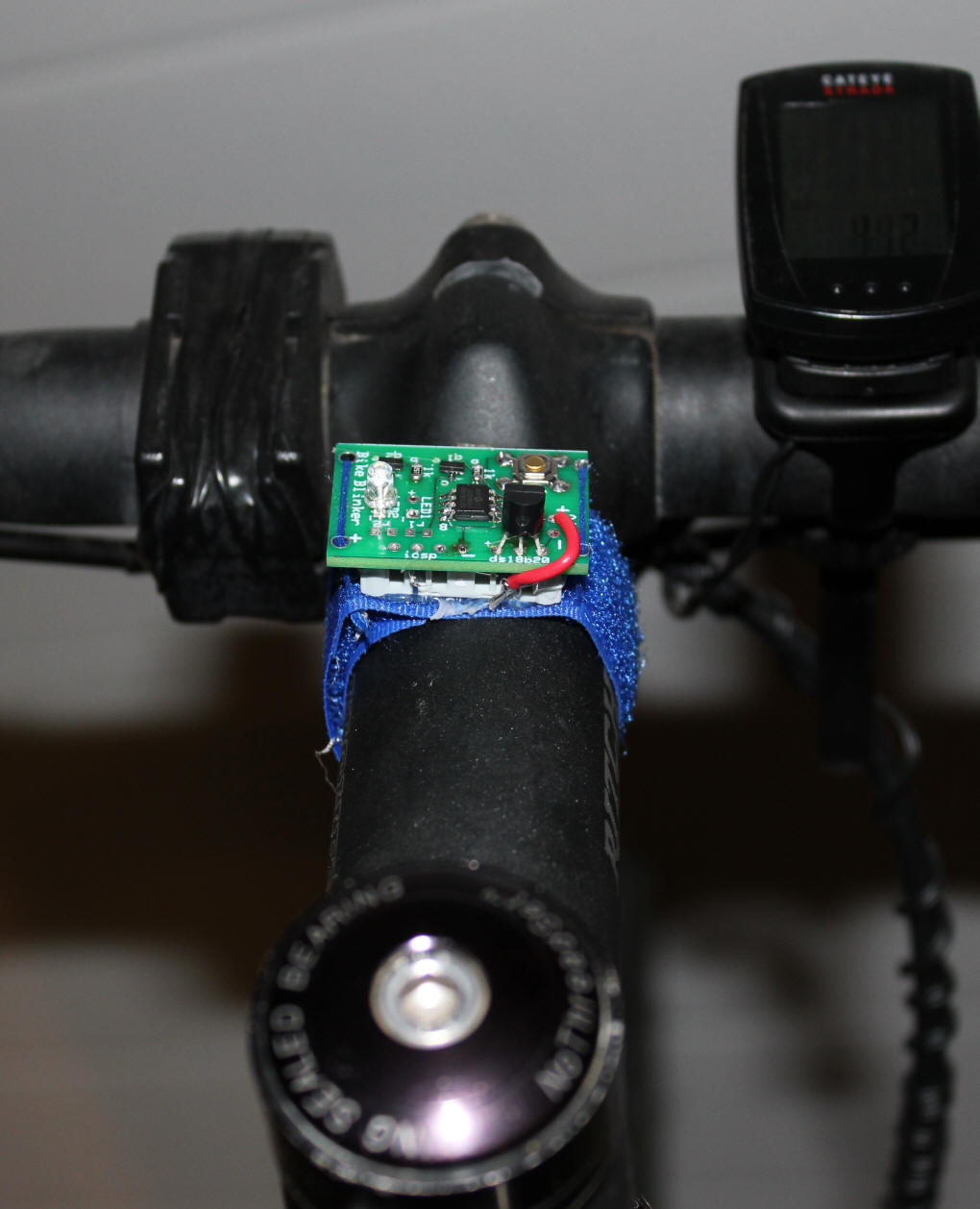
single battery to last for months & months.  A piece of Velcro was glued to the bottom of the unit to facilitate easy mounting on the bike.

The 2032 battery is housed in a small cell holder that will be glued to the bottom of the circuit board.  The one shown here is similar to this unit from Digikey:  http://search.digikey.com/scripts/DkSearch/dksus.dll?Detail&name=1065K-ND and this one from batteryholders.com  http://www.batteryholders.com/show-part.php?part=bk-5058 - There are a number of other 2032 holders that would work equally well.

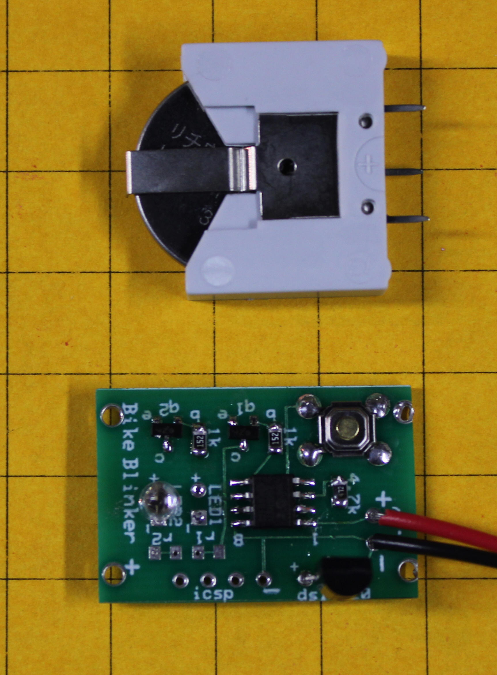
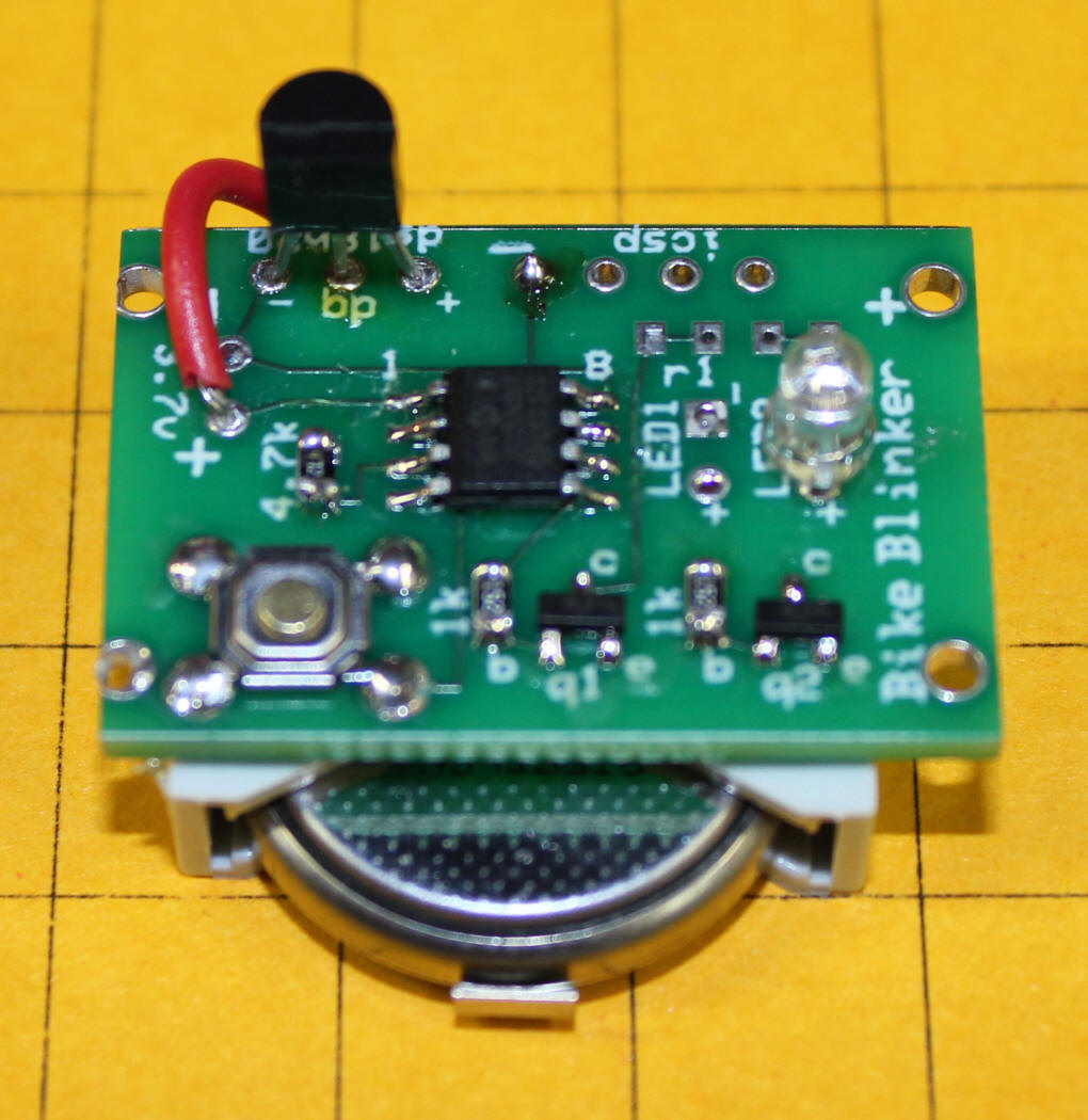
Here the cell 2032 holder has been glued to the circuit board.  The negative power lead is soldered to the negative contact that is used for ISCP and the positive lead is attached with a piece of red wire.

In this view you can see the positive connection (the red wire) and the negative connection by the "-" at top center.

To simplify mounting to the bike a section of Velcro has been glued to the unit.   The glue connection was reinforced with thread.

Software changes are again minimal.  The areas where the changes were made are highlighted in Red.

ON DEMAND _ BUTTON ONLY
'd. bodnar 12-26-09 0 fixed error between 15 and 8 F
'Modified 03-02-10 to only give temperature when button pushed - no other functions
'Modified 8-11-10 to allow button on power up to change temperature scale (f/c)
'1998 bytes of 2048 before text strings removed
'THIS WORKS: serout2 serialout, 84+16384,[bin r_temp,10,13] '84=9600- 16384=inverted data
INCLUDE "modedefs.bas"
ansel=0                 'use pins as digital rather than analog
DEFINE OSC 8            'use 8 mhz oscillator
OSCCON = $70            'set clock speed 
option_reg.7=0          'turn on weak pull ups
wpu = %00100000         'weak pull ups on pin GPIO.5 only 
INTCON = %00001100      '00xx11xx to be CCP1 mode

SerialOut       VAR GPIO.0      'pin 7
NotUsed1        VAR GPIO.1      'pin 6
LED             VAR GPIO.2      'pin 5 
NotUsed3        VAR GPIO.3      'pin 4
DQ              VAR	GPIO.4      'pin 3 One-wire Data-Pin "DQ"
ChangeSwitch    VAR GPIO.5      'pin 2
R_Temp          VAR	WORD        'RAW Temperature readings
C_Temp          VAR WORD        'Celsius Temperature
Decimal_C_Temp  VAR WORD        'store just the decimal C temperature
F_Temp          VAR WORD        'Fahrenheit Temperature
G_Temp          VAR WORD        'Generic Temperature for report (either C or F)
NEGPOS          VAR BYTE        'Sign char "-" or "+"
C               VAR BYTE        'Status of I/O port bit
Minimum         VAR BYTE        'minimum temperature (store as C or F)
Maximum         VAR BYTE        'maximum temperature (store as C or F)
Mode            VAR BYTE        'branch variable
Y               VAR BYTE        'for/next variable
Z               VAR BYTE        'temporary variable
Ones            VAR BYTE        'ones
Tens            VAR BYTE        'tens
Hundreds        VAR BYTE        'hundreds
Scale           VAR BIT         '=0 if Fahrenheit / =1 if Celsius
SleepCounter    VAR BYTE        'count times mode shown before sleep
C_neg           VAR BIT         '=1 if cold bit for C set
MinMaxReptFlag  VAR BYTE        '0=temp, 1=min, 2=max- order of minmaxreport

TPause          CON 300
BetweenPause    CON 300
Mode            = 1             'start in Temperature reporting mode
Scale           = 0             '0 =  Fahrenheit
GPIO            = %00110000     'GPIO 4 & 5 as inputs - others as outputs
DATA @0,0,0                     'start with Fahrenheit scale (0) & mode 0
READ 0, Scale                   'read saved scale (F or C)   
READ 1, Mode                    'read mode 

SEROUT SerialOut,n9600,[12,10,13,"Ver 5.1Zb Bike Blinker +PLUS+ BUTTON ONLY",10,13]
SEROUT SerialOut,n9600,["(c) d. bodnar 08-11-10",10,13]
 
VeryTop:  
LOW LED 
'''pause 1000
MinMaxReptFlag=0
'gosub showscale                 'flash "C" or "F" in Morse Code
'Note that minimum & Maximum are stored as temperature + 100 to handle negatives
Minimum         = 255           'store as temp + 100 , below 100 is negative
Maximum         = 0             'gives range of 100 below to 125 above

IF ChangeSwitch = 0 THEN        'if switch held change scale
    Scale = NOT(Scale)
    GOSUB ShowScale
    WRITE 0,Scale               'save current scale to memory
    WHILE ChangeSwitch=0        'stay here till switch released
        GOSUB showscale
    WEND
ENDIF   

start:
GOTO Temperature
Start2:
GOTO gotosleep:
'if changeswitch=0 then goto ChangeMode
'Branch  Mode, [Temperature, FullBrightFast, FullBrightSlow, FullOn, MinMaxReport]
GOTO start:

Temperature:
GOSUB Start_Convert
'serout serialout,n9600,[10,13,"-+= ",negpos,10,13 ]
IF Scale = 1 THEN 
    G_Temp=C_Temp        '0=fahrenheit, 1=celsius
    ELSE
    G_Temp=F_Temp
ENDIF

Report_Temperature:
IF NEGPOS = "+" THEN
    IF G_Temp + 100 > Maximum THEN    'save new max if new temperature is above old
        Maximum = G_Temp+100
    ENDIF
    ELSE
    IF 100-G_Temp  > Maximum THEN
        Maximum = 100-G_Temp
    ENDIF
ENDIF

IF NEGPOS="+" THEN
    IF G_Temp + 100 < Minimum THEN    'store new minimum temperature if lower
        Minimum = G_Temp+100
    ENDIF
ENDIF
IF NEGPOS="-" THEN
    IF 100-G_Temp< Minimum THEN
        Minimum=100-G_Temp
    ENDIF
ENDIF
SEROUT SerialOut,n9600,["Min/Max = ",#Minimum," ",#Maximum,10,13,10]
HIGH LED:FOR Y=1 TO 20:TOGGLE LED:PAUSE 20:NEXT Y:LOW LED  'fast blink @ start
IF C_neg = 1 AND Scale=1 THEN ' temperature is below zero Ceisius
    NEGPOS = "-"
ENDIF
IF (Scale=0 AND NEGPOS = "-") OR (C_neg=1 AND Scale=1)  THEN 'dim LED after rapid flash to show below zero temperature
    GOSUB minpwm:
ENDIF
IF ChangeSwitch=0 THEN GOTO ChangeMode 'watch for button press
PAUSE 400
'serout serialout,n9600,["G=",#G_Temp," +- ",NEGPOS,10,13]     'sign is for celsius!
Hundreds=G_Temp/100
'serout serialout,n9600,["Gh=",#G_Temp," ",#hundreds,10,13] 
IF Hundreds<>0 THEN ' show hundreds of degrees if temperature is >=100
    FOR Y=1 TO Hundreds:HIGH LED:PAUSE TPause:LOW LED:PAUSE TPause
    IF ChangeSwitch=0 THEN GOTO ChangeMode  'watch for button press
    NEXT Y
    PAUSE BetweenPause:PAUSE BetweenPause
ENDIF
IF ChangeSwitch=0 THEN GOTO ChangeMode     'watch for button press
G_Temp=G_Temp-(Hundreds*100)
Tens=G_Temp/10
'   serout serialout,n9600,["Gt=",#G_Temp," ",#Tens,10,13] 
IF Tens<>0 THEN ' show tens of degrees
    FOR Y=1 TO Tens:HIGH LED:PAUSE TPause:LOW LED:PAUSE TPause
    IF ChangeSwitch=0 THEN GOTO ChangeMode   'watch for button press
    NEXT Y :PAUSE BetweenPause
    PAUSE BetweenPause
ELSE 
    HIGH LED:PAUSE 40:LOW LED:PAUSE 40:PAUSE BetweenPause
    PAUSE BetweenPause
ENDIF
IF ChangeSwitch=0 THEN GOTO ChangeMode  'watch for button press
G_Temp=G_Temp-(Tens*10)
Ones=G_Temp
'serout serialout,n9600,["Go=",#G_Temp," ",#ones,10,13] 
IF Ones<>0 THEN ' show ones of degrees
FOR Y=1 TO Ones:HIGH LED:PAUSE TPause:LOW LED:PAUSE TPause
IF ChangeSwitch=0 THEN GOTO ChangeMode   'watch for button press
NEXT Y:PAUSE BetweenPause
IF ChangeSwitch=0 THEN GOTO ChangeMode  'watch for button press
PAUSE BetweenPause
ELSE 
IF ChangeSwitch=0 THEN GOTO ChangeMode     'watch for button press
HIGH LED:PAUSE 40:LOW LED:PAUSE 40:PAUSE BetweenPause
ENDIF
GOTO Start2
 
Start_Convert:
OWOUT DQ, 1, [$CC,$44]		  'Send calculate temperature command
REPEAT                      
    PAUSEUS 25 	  	     	  'Waiting loop until reading complete
    OWIN DQ, 4, [C]			  'Monitor for pin high transition ...   
UNTIL C <> 0 				  ' ... reading complete
OWOUT DQ, 1, [$CC, $BE]		  'Send read scratchpad command
OWIN DQ, 2, [R_Temp.LowByte,R_Temp.HighByte]	'get temperature
IF R_Temp.11 = 1 THEN          'check below zero bit
    C_neg=1
    NEGPOS = "-"
    R_Temp = ~R_Temp + 1
ELSE 
    NEGPOS = "+"
    C_neg=0
ENDIF
C_Temp = R_Temp >> 3        'Get whole # of degrees & first decimal bit
SEROUT SerialOut , n9600,["C =  ",NEGPOS,#C_Temp/2," deg. C",10,13]
F_Temp = C_Temp * 9  
F_Temp = F_Temp / 5
F_Temp=F_Temp/2 	     'remove decimal bit
IF NEGPOS="+" THEN
    F_Temp = F_Temp + 32 
ENDIF
IF NEGPOS ="-" AND C_Temp <= 36 THEN    'was 18 - caused error!
    F_Temp = 32 - F_Temp 
    NEGPOS = "+"
ENDIF
IF NEGPOS="-" AND C_Temp > 36 THEN      'was 18 - caused error!
    F_Temp = F_Temp  - 32
ENDIF
SEROUT SerialOut,n9600,["F =  ",NEGPOS,#F_Temp," deg.F",10,13]
C_Temp = C_Temp/2	
RETURN

FullBrightFast: 'full brightness - fast blink
SEROUT SerialOut,n9600,["@f",10,13] 
HIGH LED:PAUSE 60:LOW LED:PAUSE 60:GOTO start:

FullBrightSlow: 'full brightness - slow blink
SEROUT SerialOut,n9600,["@s",10,13] 
HIGH LED:PAUSE 500:LOW LED:PAUSE 500:GOTO start:

FullOn:
SEROUT 0,n9600,[10,13,"@ON",10,13]
HIGH LED
GOTO start:


ShowScale:
DIT CON 70        'Morse Code DIT
DAH CON DIT*3     'Morse Code DAH
SPACE CON DIT*5   'Morse Code space between Dits & Dahs
''serout serialout,n9600,["Sc=",#scale,10,13]

IF Scale=0 THEN    'Morse Code "F"
    HIGH LED:PAUSE DIT:LOW LED:PAUSE SPACE:HIGH LED:PAUSE DIT:LOW LED:PAUSE SPACE
    HIGH LED:PAUSE DAH:LOW LED:PAUSE SPACE:HIGH LED:PAUSE DIT:LOW LED:PAUSE SPACE
ELSE                'Morse Code "C"
    HIGH LED:PAUSE DAH:LOW LED:PAUSE SPACE:HIGH LED:PAUSE DIT:LOW LED:PAUSE SPACE
    HIGH LED:PAUSE DAH:LOW LED:PAUSE SPACE:HIGH LED:PAUSE DIT:LOW LED:PAUSE SPACE
ENDIF
PAUSE 1000
RETURN

MinPWM:
FOR Y= 255 TO 0 STEP -1
    PWM 2, Y, 3
    IF ChangeSwitch=0 THEN GOTO ChangeMode   'watch for button press
NEXT Y
RETURN

MaxPWM:
FOR Y= 0 TO 255 
    PWM 2, Y, 3                              
    IF ChangeSwitch=0 THEN GOTO ChangeMode  'watch for button press
NEXT Y
RETURN

GoToSleep:
Mode=Mode-1
WRITE 0, Scale      'save current scale 
WRITE 1, Mode       'save current mode
SEROUT 0,n9600,[10,13,"@Sleep",10,13]
FOR Y= 255 TO 0 STEP -1  'dim showing going to sleep
    PWM 2, Y,3
NEXT Y
LOW LED:
INTCON.0 = 0	'Reset the  Port change bit 
IOC=0
LongSleep:
SEROUT 0, n9600, ["Z", 10,13]
PAUSE 3000
INTCON.0 = 0	'Reset the  Port change bit
gpio.5=0        'reset switch pin
IOC = %00100000 'enable INTERRUPT ON CHANGE on gpio 5 
SLEEP 65000
IF intcon.0=0 THEN GOTO longsleep
INTCON.0 = 0	'Reset the  Port change bit   
IOC=0
FOR Y= 0 TO 255  'brighten LED to show waking up
    PWM 2, Y,3
NEXT Y    
SEROUT 0, n9600, ["xZ", 10,13] 
INTCON.0 = 0	'Reset the  Port change bit   
'''pause 500
GOTO VeryTop:

ChangeMode:
RETURN
 

Some Thoughts on Water-Proofing
Both of these circuits are likely to experience rain and other insults from the environment.  I have used the handlebar unit for well over a year and have not done anything to protect it from the elements.  The battery and its contacts have needed periodic cleaning and the switch has malfunctioned when drenched but for the most part the board has survived admirably.  

The garden blinker has also worked well in the rain but I am convinced that some of the components are sure to corrode and fail if I do nothing more.  I may "pot" the whole thing in epoxy or put the electronics in a small plastic pill box and see how it holds up.  Even then there are likely to be corrosion issues.  If anyone has any suggestions for dealing with moisture please drop me a note (dave@davebodnar.com)

Conclusion
I think that you will find that these two variations of the Bike Blinker +Plus+ make it an even more interesting and useful device.  I encourage you to give it a try.  Please let me know if I can help.

Parts List
Garden Blinker:

On Demand Blinker