Multi-Function Crossing Signal Controller
Building the Kit
Revised 10-04-11
updated 12-20-13
Click here to jump to the new IR Trigger
modification
Click here for the new
IR sensor notes
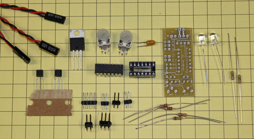
| Parts The parts for the kit are shown below.
Clockwise from the upper left they are:
- 3 plugs for LEDs and power
- 7805 Voltage regulator
- 2 potentiometers
- capacitor - positive side is marked with a bar
- PIC processor
- socket for the PIC
- circuit board
- 2 red LEDs
- 2 - 470 ohm current limiting resistors
- 2 - 10K resistors (black / brown / orange)
- 2 - 1K resistors (black / brown / red)
- Headers - 2x2, 2x3, 3 @ 2 pin, 4 pin
- 2 - 2N2222 NPN transistors
In addition you will need a power supply or batteries, solder,
soldering iron, wire cutters, etc. Missing from the photo are
the three jumpers that select modes. |
 |
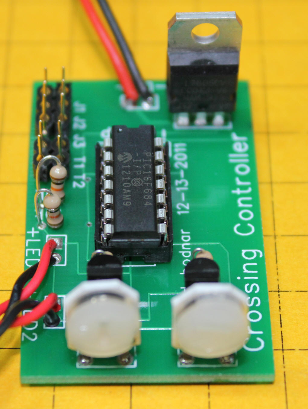
Step 1
Solder the 7805 voltage regulator, capacitor and power pins to
the circuit board. Note the orientation of the 7805 and
capacitor. The red/black cable attaches to a source of 7-20
volts DC.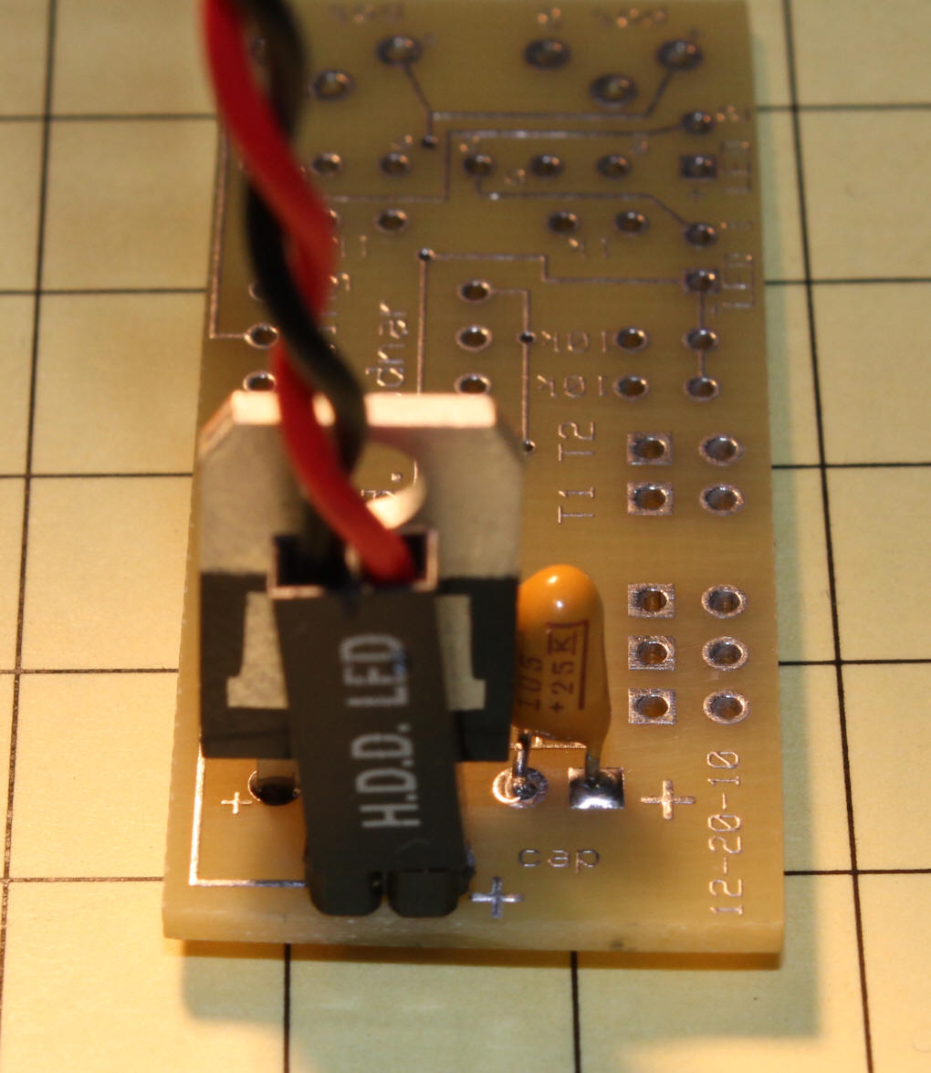
Clip off leads that extend through the board. Check
carefully for solder bridges, they are easy to miss!

|
Step #2
Solder the 14 pin socket to the circuit board. Be careful
that all 14 pins come through the holes in the board as it is easy
to bend one over. Also note the orientation of the socket.
Pin 1 is in the upper left in this photo. The four pins above
the socket are not needed unless you plan on reprogramming the PIC
processor.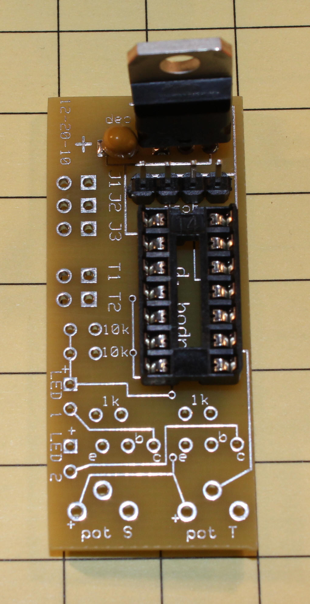
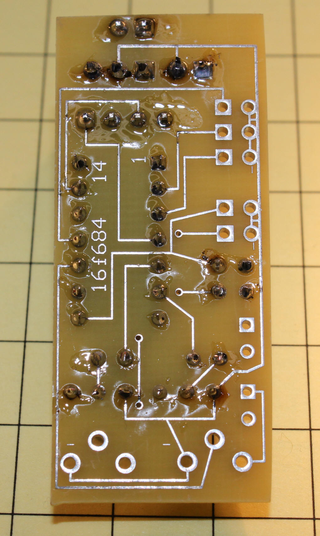
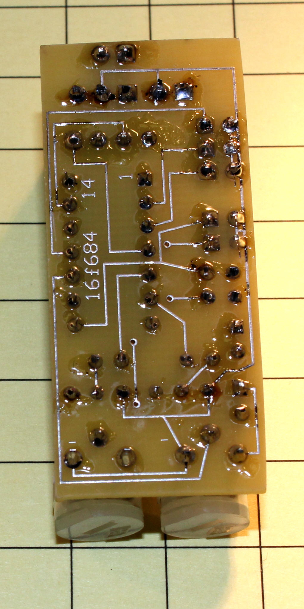
Check after soldering each component to be certain that there are
no solder bridges. The socket pins are very close together and
bridges are easy to create.
|
Step #3
Add the four resistors and the two transistors. The
transistors must be oriented as shown. The 1K resistors are
behind the transistors and the 10K resistors are at the bottom of
the photo. Resistors can be installed either way.
Carefully insert the microcontroller making sure that no pins are
bent under - note that pin 1 (marked with the dot at the bottom left
in the photo) has to been located as shown! There is also a
notch at the left end that marks pin 1, too.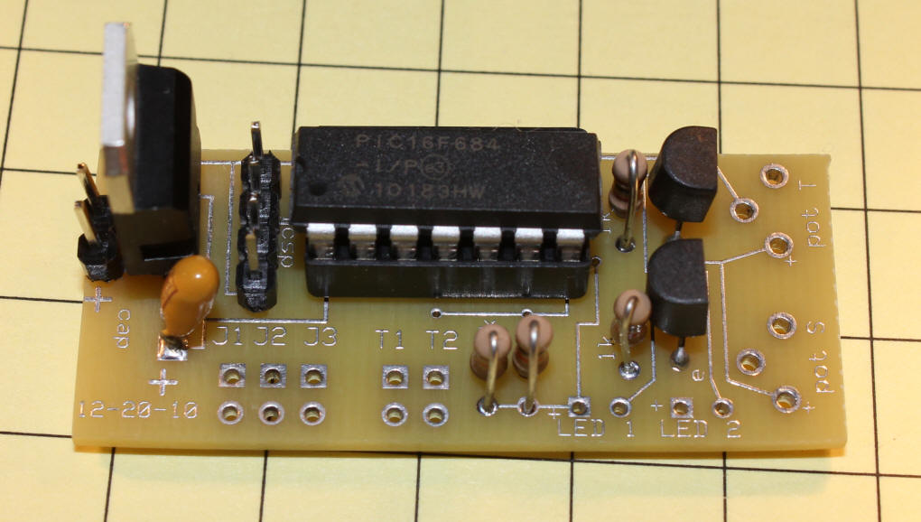
Again, check for bridges and clip leads close to the board.
|
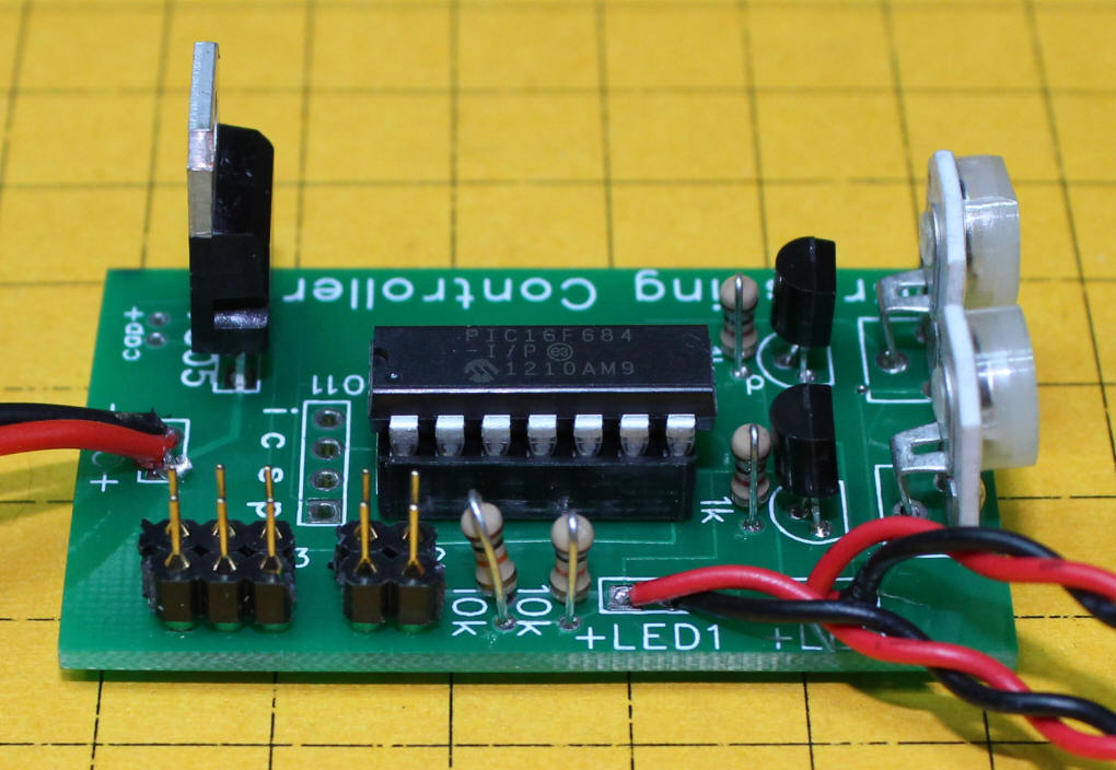
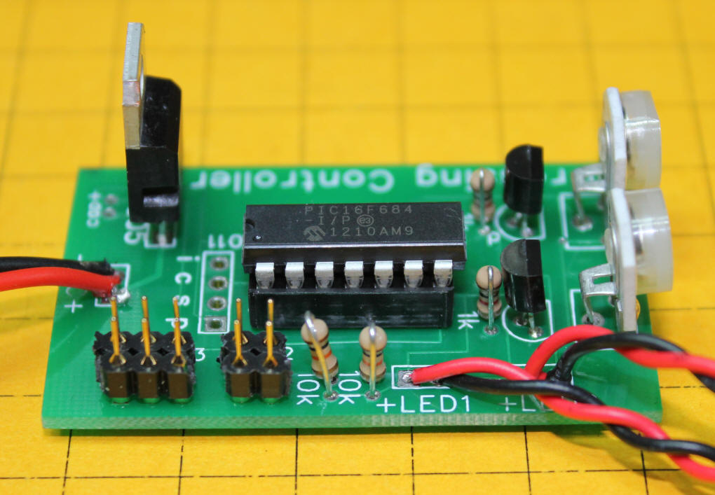
Step #4
Install and solder the two potentiometers and the four sets of
pins as shown.
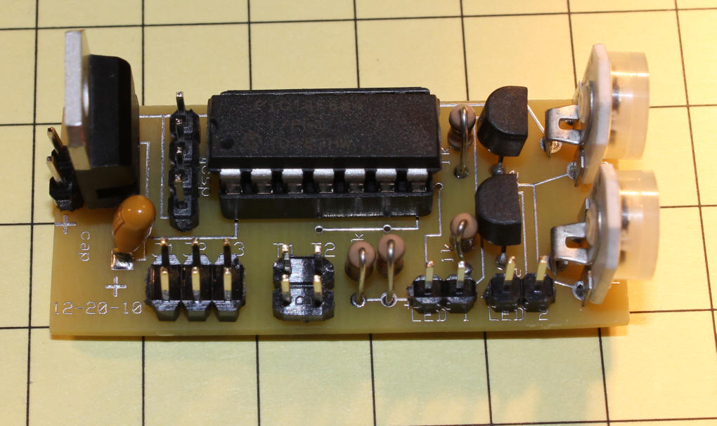 |
Step #5
This photo shows the three mode selection jumpers installed
(bottom left) and the plugs for the two LEDs or incandescent bulbs.
If using LEDs the red wire must go to the left as shown.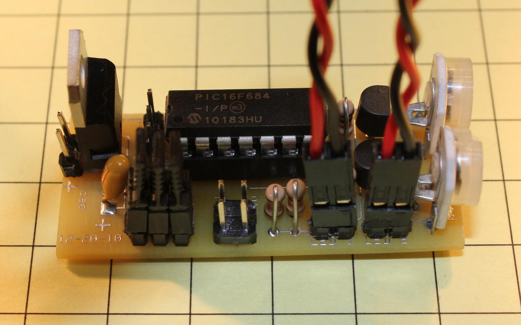
|
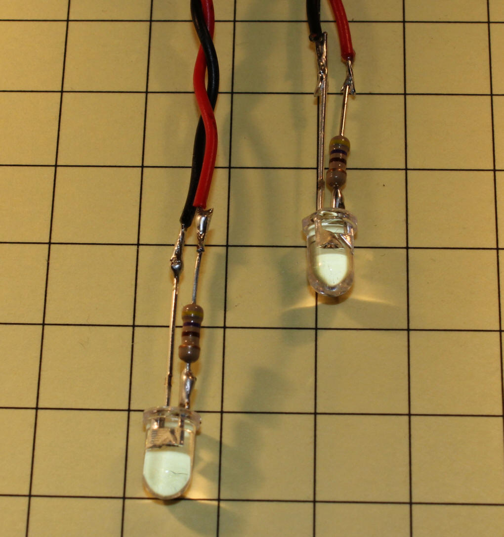
Step #6
Solder the 470 ohm current limiting resistors to the LEDs.
 |
Modification for Incandescent Bulbs
The board is designed to provide 5 volts to illuminate LEDs. If
you want to drive small incandescent bulbs with 12 volts you need to make a
few modifications to the board.
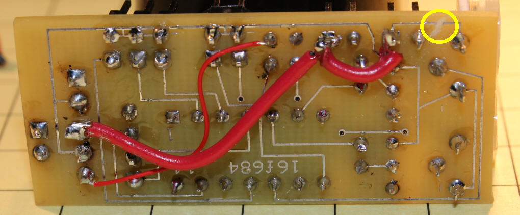
Three traces need to be cut. Two on the top of the board - circled
in yellow and one on the bottom of the board. I used a small Dremel
cutting tip but a razor blade will do. Just make sure that the trace
is completely severed.
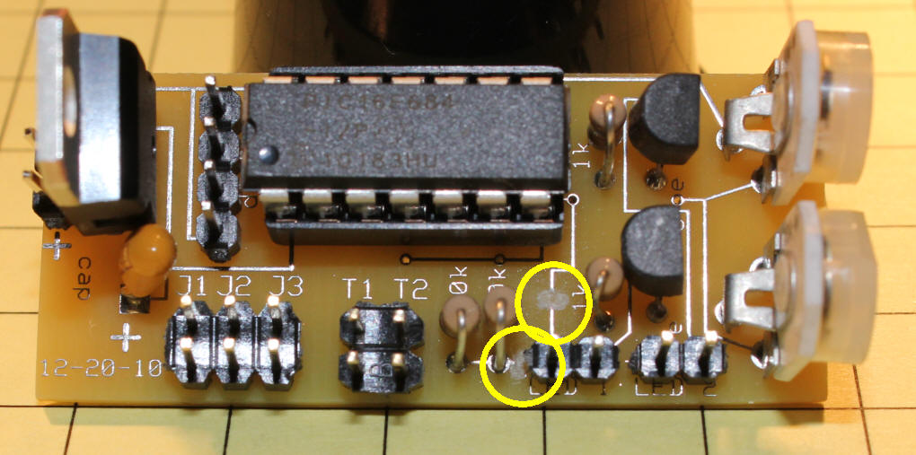
One jumper must be added from the 5 volt side of the 7805 (thin red wire)
and one from the input side of the 7805 (heavier red wire) - note that the
12 volt jumper goes to two pins.
After the modification has been made LEDs can still be used but the
current limiting resistor value may need to be increased from 470 ohms to
1000 ohms. |
|
IR Trigger Modification I
was recently contacted by a gentleman who wanted to use the crossing
controller with an Infrared Trigger similar to the one described here:
http://www.trainelectronics.com/IR_Train_Detector_5-2007/index.htm
He also wanted to use the crossing lights with a larger outdoor signal.
This required the Incandescent Modification, above, but with larger gauge
wire as he would be using 20 watt Halogen bulbs.
The schematic for the Crossing Controller and IR Trigger are shown below.
I considered making up a secondary board that would house the electronics
for the IR detector but opted to place the small 12F683 microcontroller atop
the 16F684 chip on the crossing controller. This would allow the
smaller chip to use the existing voltage regulator and would make for a more
compact package.
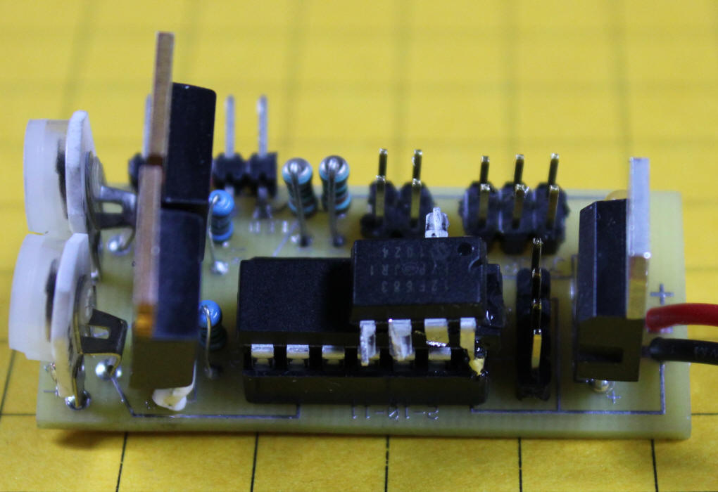
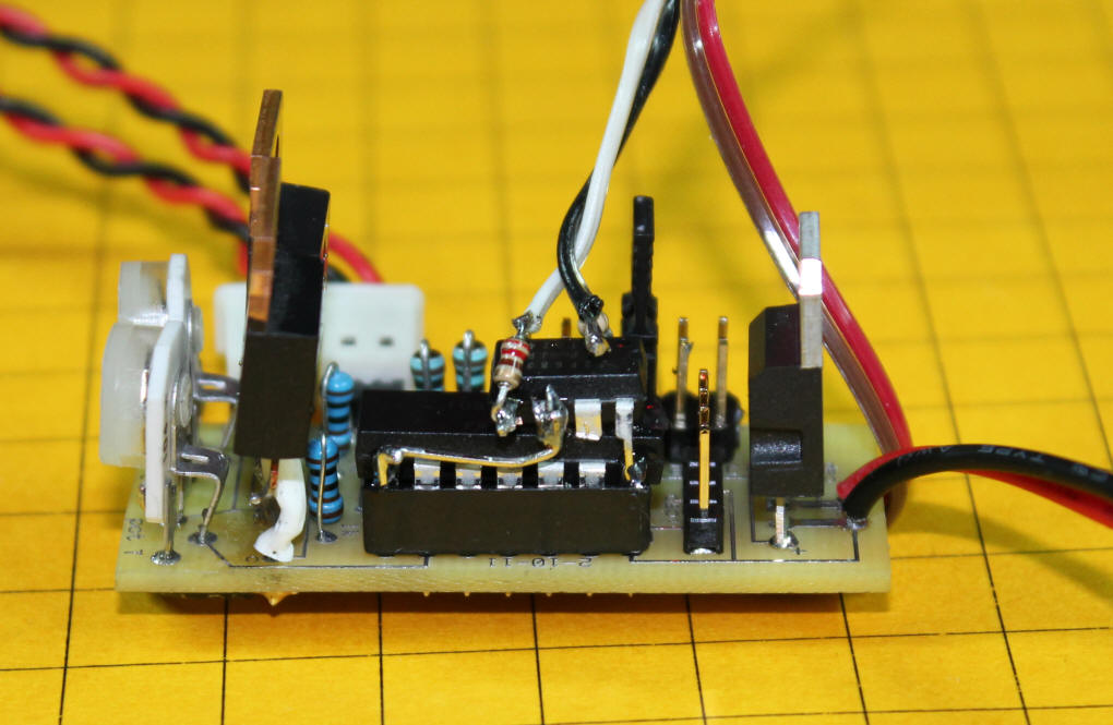
In this photo you can see that the 12F683 has pins 1 and 8 soldered
directly to pins 1 and 14 on the 16F684. These two pins are +5 volts
and ground. The other pins are bent out a bit so that they don't come
into contact with those that are below. Please note that the 12F683
must be programmed BEFORE soldering it to the other chip as no provision is
provided for programming it once it is installed.
Here you can see the heavy wire that has been used to deal with the high
current drawn by the 20 watt bulbs.
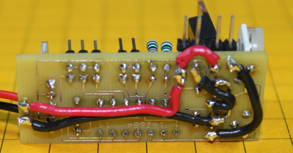
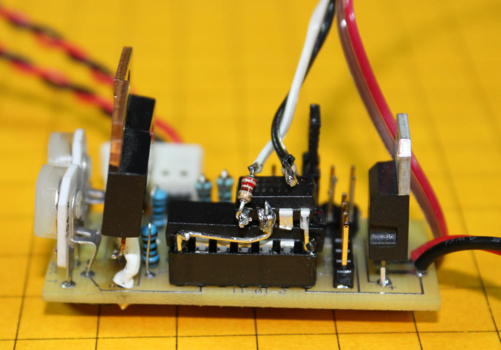
This close-up shows the wiring for the IR Trigger. Pin 6 on the
12F683 goes directly to pin 8 on the 16F684. A 220 ohm resistor is
soldered to pin 6 on the 12F683 - it connects to the lead on the sensor
module that drives the IR LED. A 1000 ohm resistor is soldered to pin
2 on the 12F683 - it goes to the output of the IR detector.
|
|
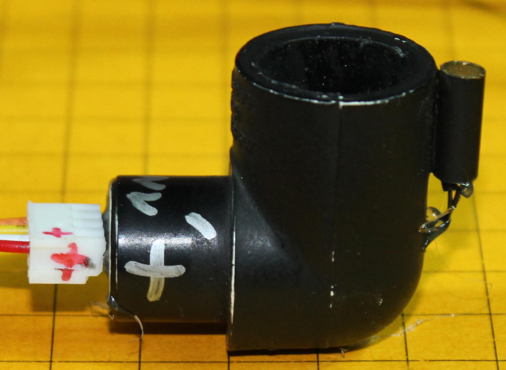
The reflective IR Detector is shown here. The IR LED is in the small
cylinder at the far right. The IR Detector is in the larger round
cavity. The plug that goes to the circuit board is at the far left.
Note that its's positive (red) wire end must go to the lead on the sensor
marked with a "+" sign.
|
|
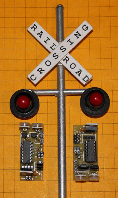
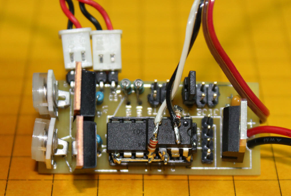
A revised board is now being used with this project. The photos below will
highlight the differences between the two boards
The pins in the upper right corner are easier to install and solder if there
are jumpers on them as shown.
.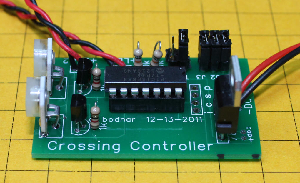
Note that the mode selection pins are longer on the end that extends above
the board.
The red / black wires on the left are power for the board - 7.5 to 12 volts
DC.
The two pairs of red / black wires in the lower right go to the two LEDs. The
current limiting resistors are at the ends of these wires.
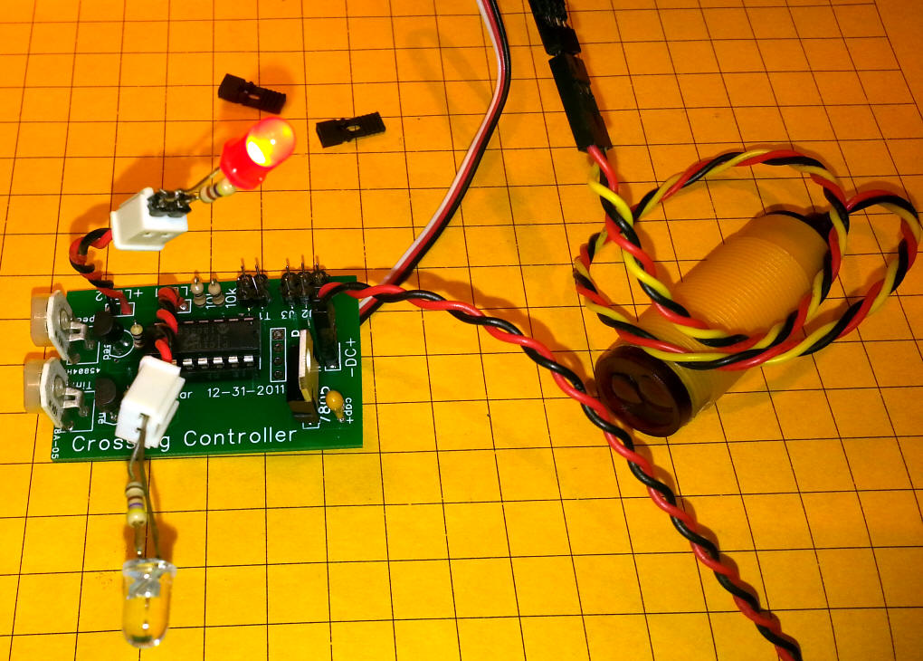
New IR Sensor
A new, self contained IR sensor can easily be connected to the circuit.
It requires a three wire connection, +5 volts, ground and data. I use a 3
wire servo cable with the wires rearranged.
This photo shows the completed board conected to two test LEDs and the IR
sensor - the end of the sensor with the two black plastic lenses is pointed
towards the item to be detected.
The IR sensor has a three wire cable. The red wire goes to 5 volts, the
black to ground and the yellow goes high when an object is detected. A 3
wire male servo cable is used to connect the sensor to the circuit board.
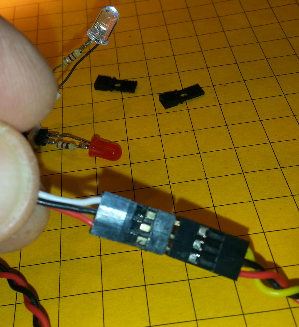
The yellow from the sensor goes to the white wire on the servo cable and is
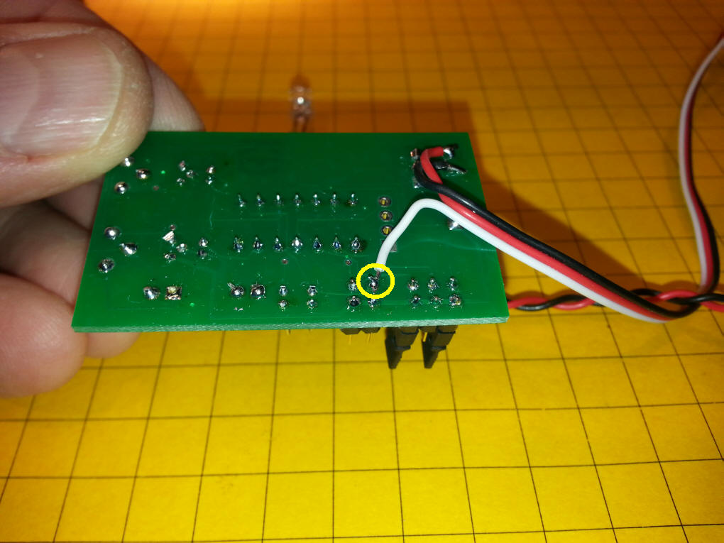
soldered to the inner connection to the first trigger on the circuit board.
The connection is circled in yellow. The red and black wires are soldered
to the positive and negative pads for the small yellow capacitor.
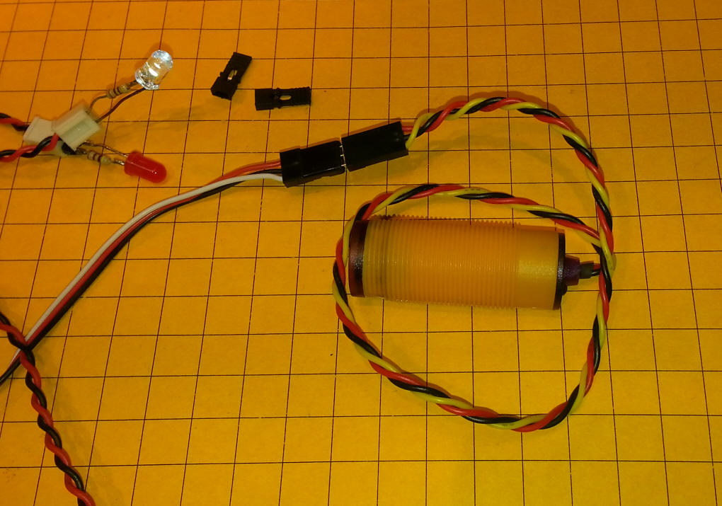
This photo shows the sensor connected to the servo cable and the two test
LEDs.
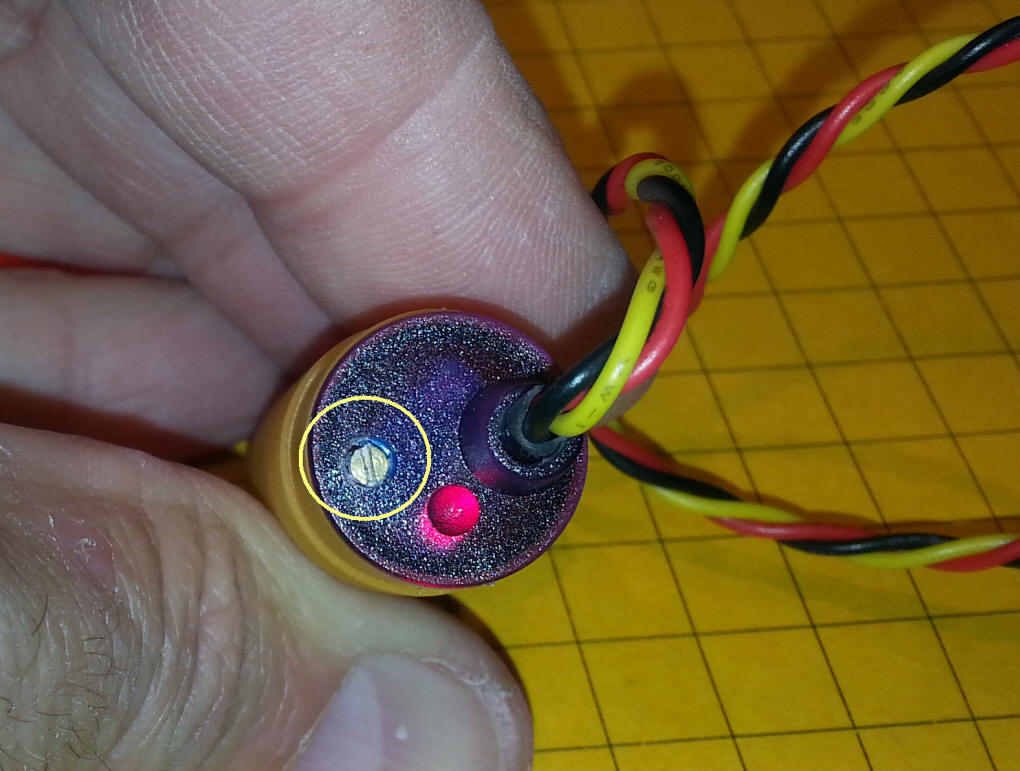
The sensitivity (range) of the sensor can be adjusted by turning the small
screw on the back of the sensor, circled in yellow. Turning it counter
clockwise makes it less sensitive and turning it clockwise makes it more
sensitive. The small red LED beside it lights when an object has been
detected.