| Introduction I have used a number of methods of detecting a train's position in a layout. Each method has its advantages and disadvantage. I recently read a description of a differential train detector that made use of a comparator and two phototransistors. My thanks to the author of the article, Geoff Bunza. While I am sure that the circuit described in Model Railroad Hobbyist works well I prefer to use an inexpensive microcontroller rather than a comparator for this circuit. What follows is a description of my experiments with a differential train detector. |
| Circuit Description In the circuit the brightness detected by two phototransistors (Q1 and Q2) is read by the microcontroller's analog to digital channels and compared. Since one phototransistor is mounted outside of the railroad's rails and the other between the rails a passing train causes a shadow to fall on one of the phototransistors. The change in brightness is noted and the LED is illuminated until the two phototransistors again see the same brightness level. |
| Schematic The schematic shows the two phototransistors, Q1 and Q2. Their collectors go to +5 volts and their emitters go to ground through a 10K resistor. The four pin header to the far left is for programming.
|
| Software for PIC12F683 The program is written in PIC Basic Pro. The main loop of the program which reads the phototransistors is highlighted.
ansel = 0 'all inputs digital |
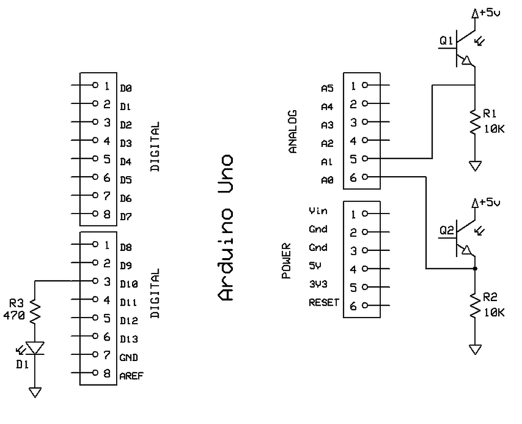
| Arduino Version The code and circuit shown here will work with an Arduino UNO and others. You should note that the schematics and code are very similar. |
 |
// Test of differential train detector on Ardudino
// Connect emitter of phototransistor to ground through a 10K resistor
// Connect the emitter of phototransistor to Pin A0 or A1
// Connect collector of phototransistor to +5 volts

// Connect LED to pin 10 through a current limiting resistor


const int PhotoT1 = 0; // phototransistor - pin A0
const int PhotoT2 = 1; // phototransistor - pin A1
const int DarkDetect = 10; // LED
int PTRead1;
int PTRead2;
int Trigger;


void setup() {
  pinMode(DarkDetect, OUTPUT);
  Serial.begin (115200);
  Serial.println("Differential Light Test v0.1");
}

void loop() {
  PTRead1 = analogRead(PhotoT1);
  PTRead2 = analogRead(PhotoT2);
  Trigger = (PTRead1 + PTRead2) / 2;
  Trigger = Trigger / 5;
  Serial.print("Trigger ");
  Serial.print(Trigger);
  Serial.print(" PTRead1 ");
  Serial.print(PTRead1);
  Serial.print(" PTRead2 ");
  Serial.println(PTRead2);

  if (abs(PTRead2 - PTRead1) > Trigger) {
    digitalWrite(DarkDetect, HIGH);
  }
  else {
    digitalWrite(DarkDetect, LOW);
  }
  delay(500);
}
|
