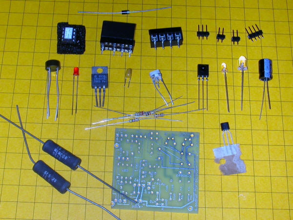
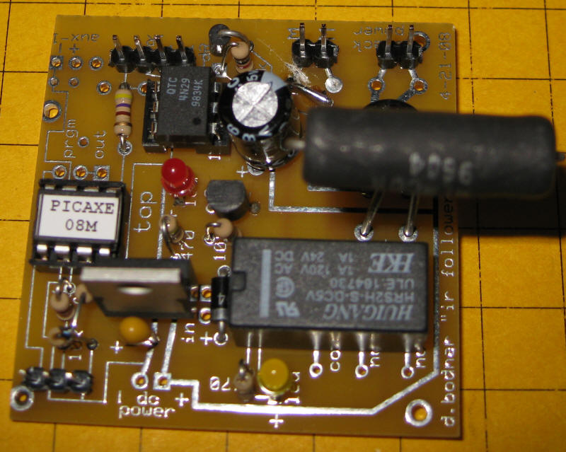
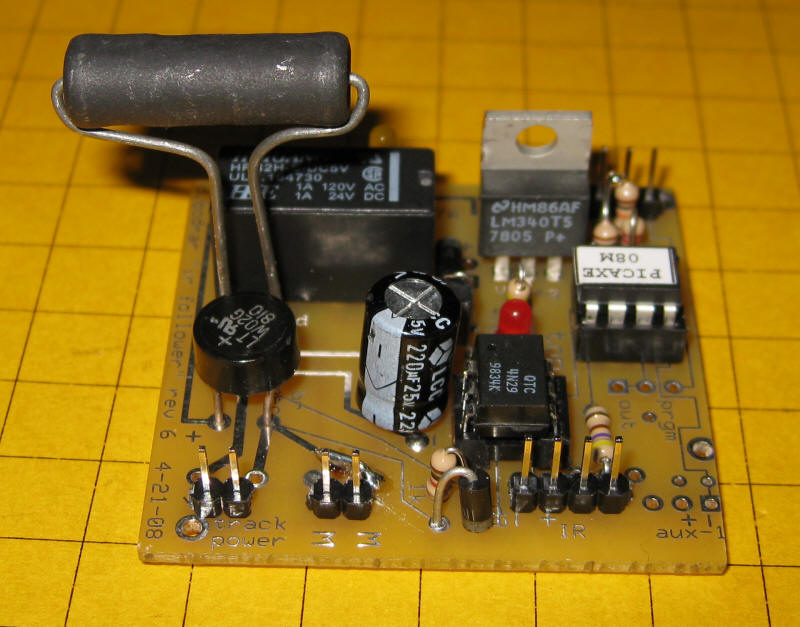
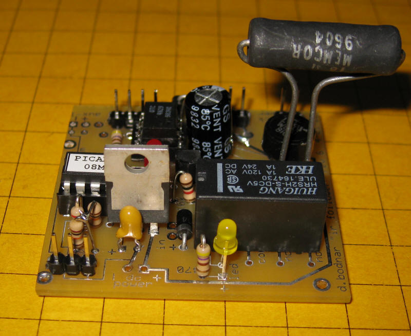
| The parts for the updated (2008) kit are shown below.
Click here for the original construction manual in Word format. The PICAXE and the DPDT relay are both in sockets. The 4 pin screw connector (top row center) can be used or two 2 pin headers can be used if space is a problem as the capacitor may hit the screw connector. There are two IR LEDs - on3 3mm and one 5mm - either can be used. A pot is included to vary the power to the IR LED but it can be bypassed and the 180 or 220 ohm resistor can be used for current limiting. The two 18 ohm power resistors are in the lower left. Some experimentation will be needed to determine if one or both should be used. In the rail truck application (shown below) the two resistors are in series with a switch that can short out the 2nd resistor. When the switch is "off" the resistance is 36 ohms and the slowing is significant. When the switch is "on" the resistance is 18 ohms and the slowing is less.
|
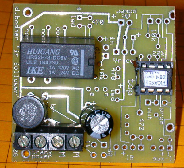
| The IR LED and IR sensor connect through the 4 holes at the
bottom marked "IR" - "aux" is not used. The current limiting
resistor goes where the board is marked 470 - I generally use a
smaller resistor, 180 to 220 ohms. The black four screw
pin connector (bottom left) can be replaced by two sets of 2 pin
headers as mentioned above. Note the orientation of the
bridge rectifier. The three holes above the relay connect to
the unused contacts and can be utilized for other purposes.
|
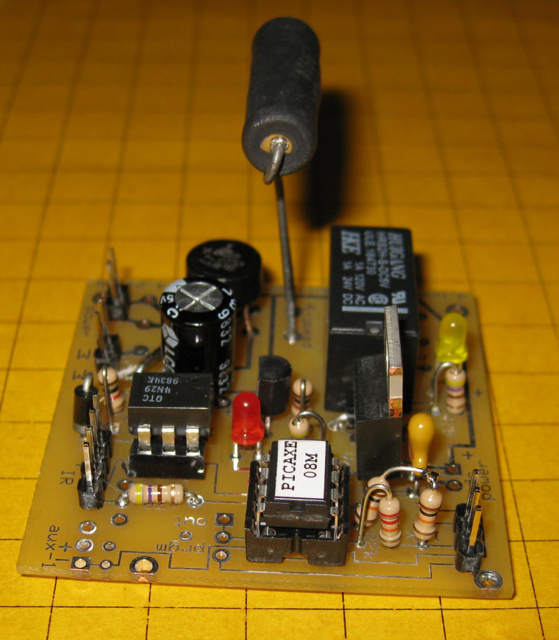
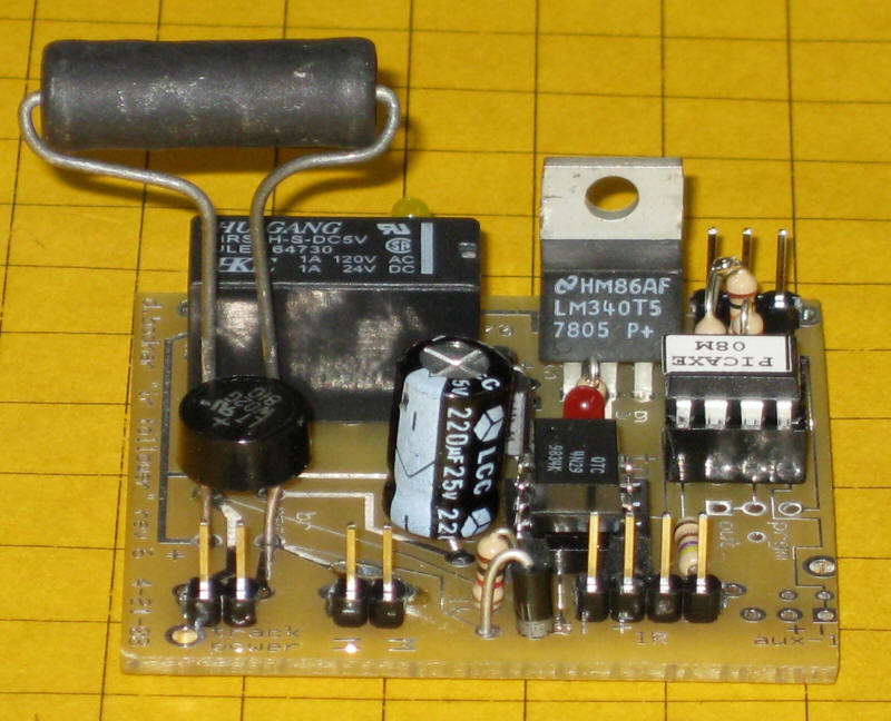
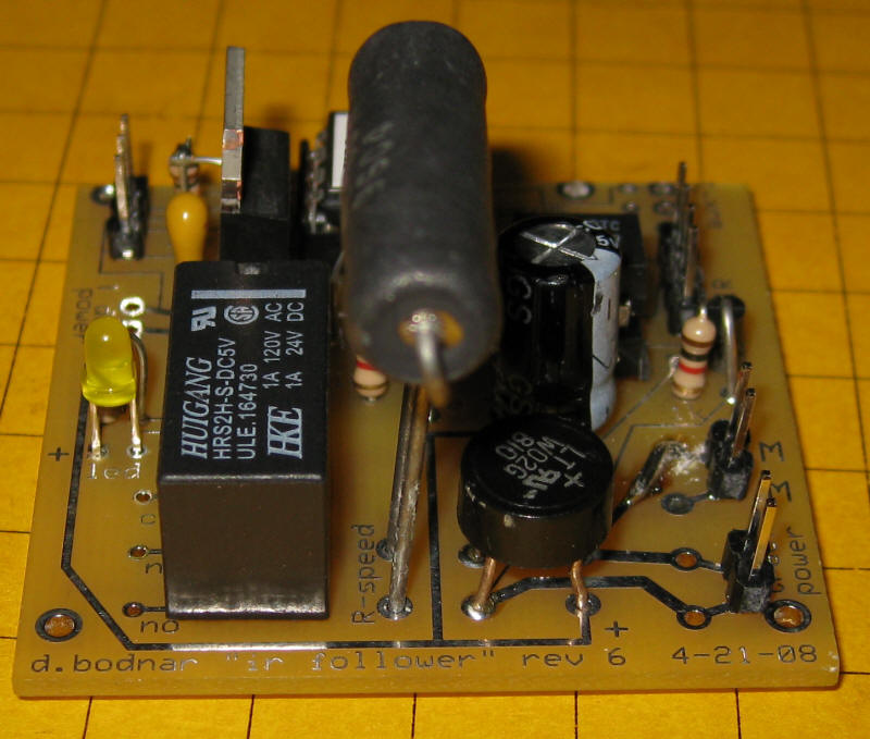
| Note the small switch in the lower right - it selects 1 or 2
resistors for speed dropping.
|
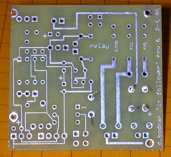
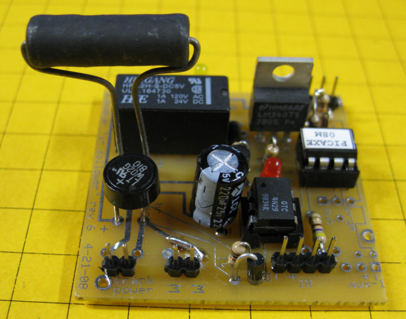
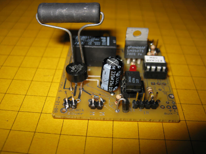
| Note the cut on the motor trace at the top just right of center
|
|
| Software
rem d.bodnar 4-20-08 rev3b
|