| Introduction When I built a throttle for my DCC++ controller (see: DCC++ Talking IR Throttle ) I wanted to add to its functionality by including a simple point-to-point controller that would automatically move a DCC equipped trolley or small engine back and forth on a piece of track. There were two things that I needed to make this work
|
| Reed Switches There are any number of sensors that can be used. My first test unit had a small reed switch between the rails at each end of the track. A small magnet was affixed to the bottom of the trolley. When the magnet passed over either reed switch it closed and the Arduino throttle responded appropriately. The reed switches are wired in parallel so that only one Arduino input pin needed to be used.
While this is an inexpensive and reliable solution it required a modification to the trolley, the addition of a magnet to its bottom. It also required the undivided attention of the Arduino as the pulse from the rapidly closing / opening reed switch would only last a fraction of a second.
|
| Current Detectors If you isolate both ends of the point-to-point track and install a current measuring device the Arduino can react to the trolley entering one end of the track or the other. The current measuring method that I have found to be most responsive and easy to implement involves running a coil of wire from the feed line to the isolated sections through another coil. Since DCC is an alternating current, a voltage will be induced in the second coil. The advantage of this method is that it does not require any change to the trolley. Again the two ends are wired together before passing through the coil so that only one sensor is needed.
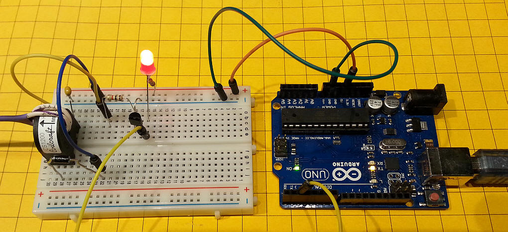
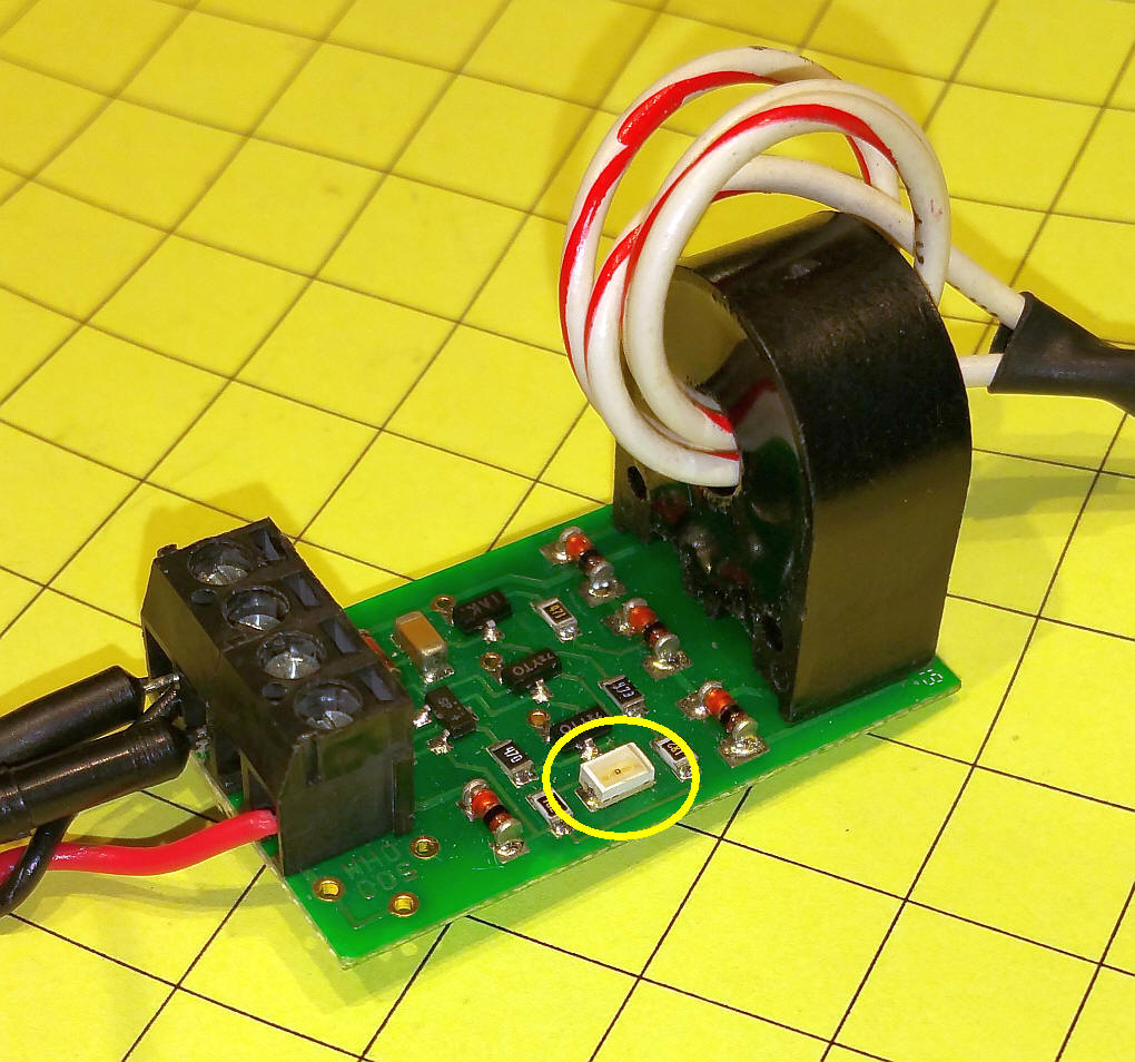
Here is a photo of a test sensor (the coil is at the far left) connected to a simple 1 transistor circuit and then to an input pin on the Arduino.
The schematic of the sensor circuit is shown here. The transistor is a general purpose NPN transistor such as a 2N2222. The diode is any small silicon diode such as a 1N4001 or a 1N4004. The capacitor is a 0.1 uf and the LED can be anything that you have handy. |
|
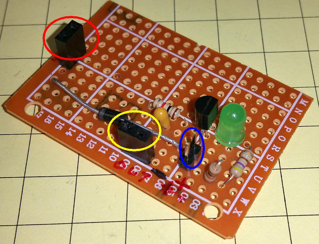
This sensor detected the current drawn when a 2k resistor was put across the track. That makes it a simple matter to add a resistor between the wheels on a piece of rolling stock to keep the block detector active as a train passes through it. Adding a light (an LED and a 470 ohm resistor) to a car would work, too. This is one of the test circuits that I built on a prototype board. The coil connects to the pins circled in red, the output to the pins in yellow and power goes to the pins circled in blue.
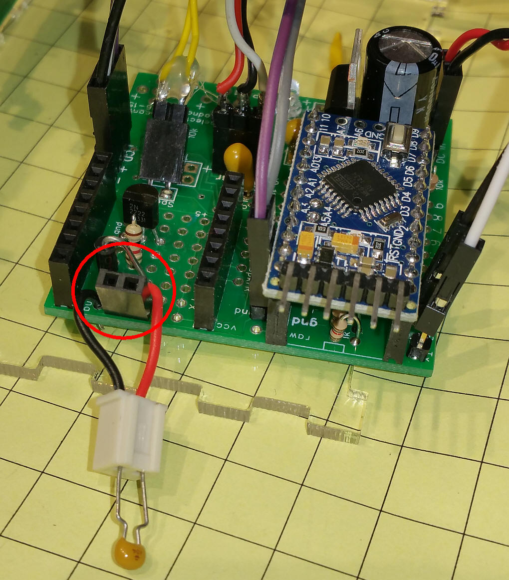
This photo shows the circuit built onto a small prototype area on the throttle controller board. The coil goes to the pins circled in red. The capacitor that extends to the bottom of the photo is in a small socket so that I could experiment with different values. The 0.1 uf worked best.
|
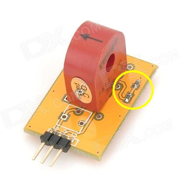
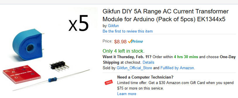
| Coils for the Current Sensor You can purchase a current sensor like this one from Deal Extreme. Most such current sensors have three leads marked S, V and G (signal, voltage & ground ). I have found that none of them actually use the positive (V) terminal. They do, however, have a resistor or two wired in parallel with the internal coil. This is called a "burden" resistor. (see the circled components in the photo below) These resistors must be removed to work with the circuit that I used. They can be removed with a soldering iron or the trace between the can be cut with a razor knife or Dremel. You can also remove the coil itself from the circuit board leaving the resistors behind.
http://www.dx.com/p/ac-ta12-100-current-sensor-module-for-arduino-white-red-161183#.VD6RPhbEf5A
Similar coils are also available from Amazon and eBay. Make sure that the coil does not have an internal burden resistor that you will not be able to remove. I have ordered some coils, that are not mounted to circuit boards, to see if they work as well as the others. The items are inexpensive at less than $2.00 each.
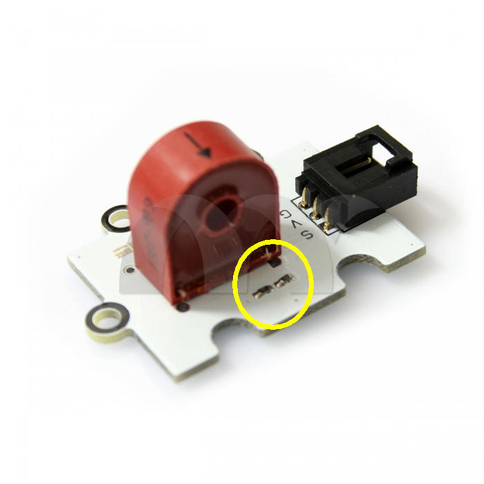
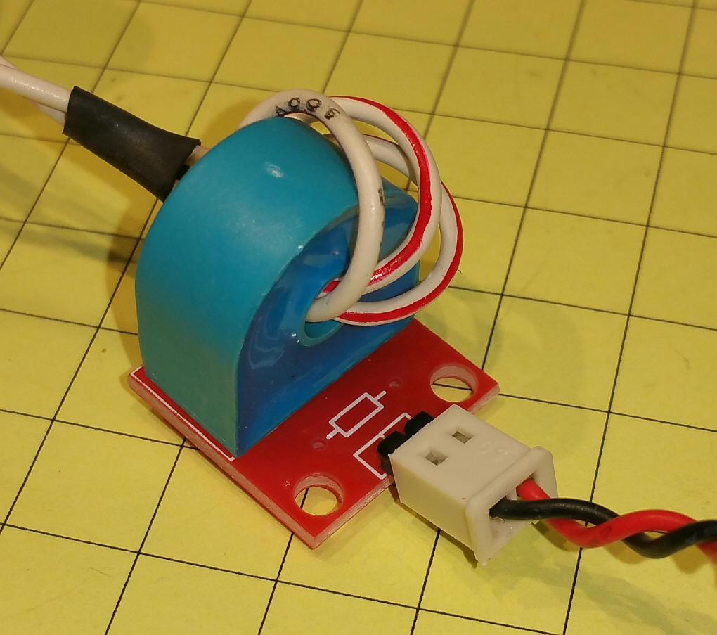
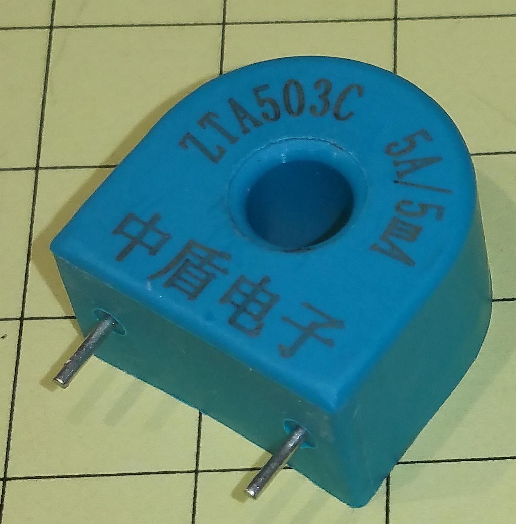
I tested the coil, without the burden resistor, and it works as well as any of the others and at a very attractive price! Note that the resistor has NOT been installed on the small circuit board.
You could also skip the board and solder the wires to the two pins that extend from the bottom of the coil.
|
|
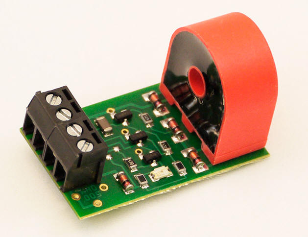
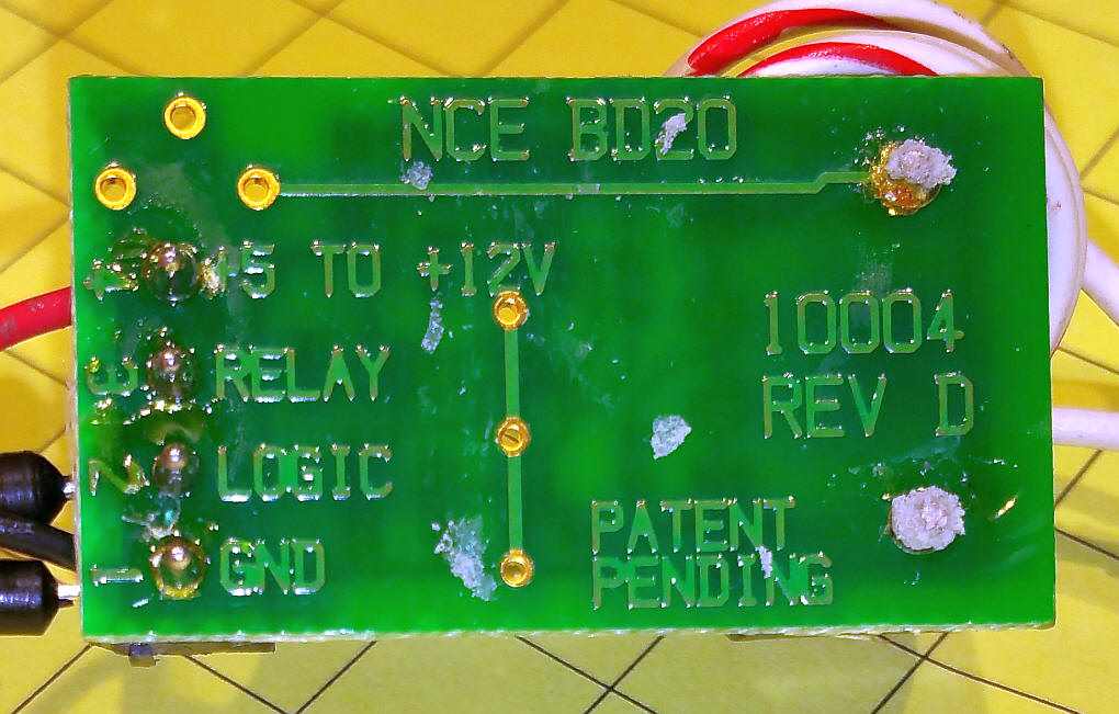
NCE Current Sensor If you would like a complete sensor unit that requires no soldering you can get the NCE DB20 Block Detector for less than $15.00.
It has a four terminal block at one end and the coil at the other. To set it up just wrap the wire that provided power to the isolated end blocks through the hole in the coil. Two or three turns should be sufficient. Connect 5 volts to the power terminal, connect ground to the negative terminal of your power source (likely to come from the Arduino) and connect the "logic" terminal to the input pin on the Arduino.
When working on 5 volts the activity LED (circled in the image below) is quite dim.
This sensor detected the current drawn when a 4.7k resistor was put across the track. It is quite a bit more sensitive to current than the one I built. |
|
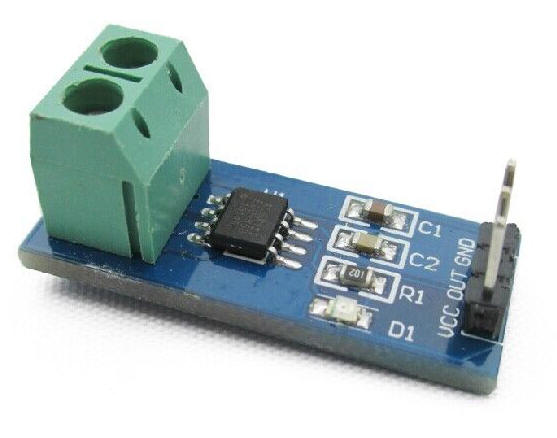
Observations while testing the
ACS712 current sensing module Modules such as the one shown below look to be an ideal solution to detecting current being drawn on a section of train track. Unfortunately my observations while testing the 5 amp module were disappointing. At first I thought that the module would not work at all with DCC which is an AC voltage as these devices are designed to measure DC current. An article, found here: http://thenscaler.com/?p=514 , provides a software solution to reading the AC current that is found while using DCC. Unfortunately I found that it was not very sensitive when used with HO locomotives that were running at low speed and drawing very little current.
|