I have been experimenting with a number of off-the-shelf H-Bridges that are normally used to operate motors with an eye towards using them to give higher amperage options to the DCC++ system. A number of my experiments are in the sections below.
My latest tests have been with a 43 amp (advertised power! ) H-Bridge that I got on eBay for about $12.00. They are available from a number of vendors - search eBay for BTS7960B 43A H-Bridge
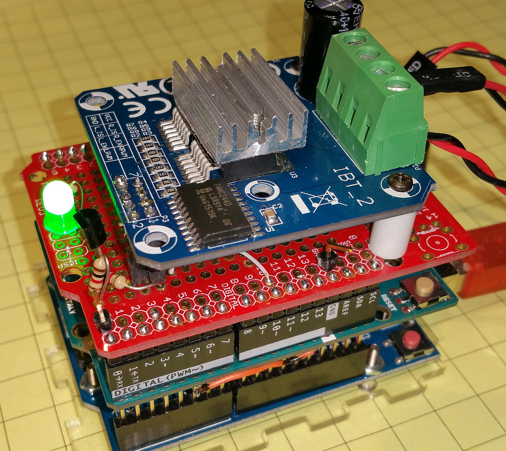
The power and motor (DCC) output connects through a 4 pin screw terminal block at the top in the photo below. There are 8 pins at the other end of the board that connect to the Arduino. In this photo I have extended these pins to a piece of prototype board to simplify connections and to provide space for an adapter circuit that is needed to use this device with DCC++.
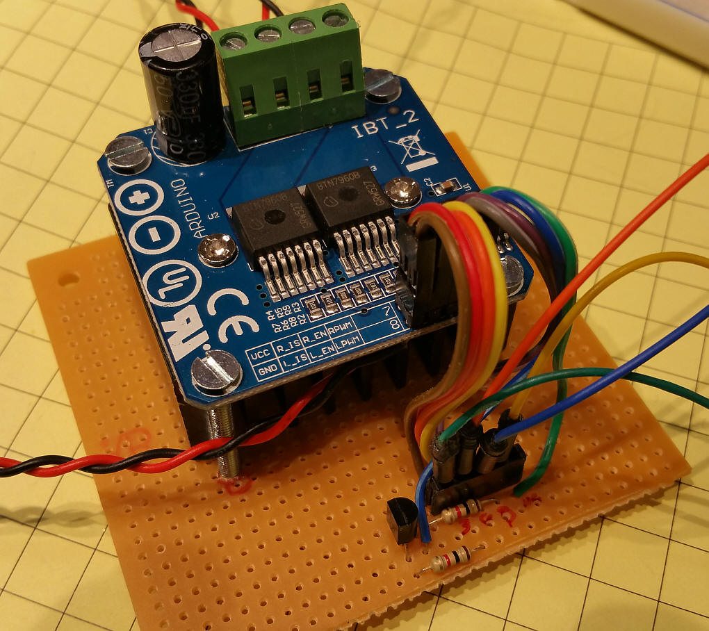
The H-Bridge wants to have two separate PWM inputs, one for rotating in one direction and the other for rotating in the opposite direction. Since the DCC++ system supplies one PWM output a single transistor and two resistors are used to toggle the PWM to the two input pins.
There are four connections to the Arduino: Ground, Pin 3 (for power on/off), pin 10 (PWM - jumpered on the Arduino to pin 12) and pin A0 (an analog input pin that receives the current sense information from the H-Bridge.) Please make sure that you connect this current sense pin to the Arduino directly, not through any motor shield that may be installed, or it will not report correctly.
The two current sense pins (5 and 6 in the diagram here) are wired together and connected to the DCC++ controller. 5 volts DC power is supplied to the board through pin 3 on the Arduino which provides 5 volts when the power is ON.
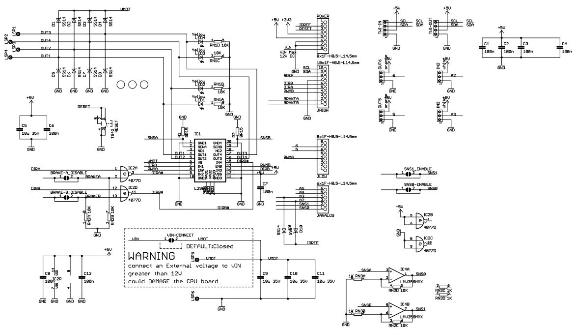
Details on the booster and the full schematic are here: http://www.trainelectronics.com/DCC_Arduino/DCC_Booster/index.htm
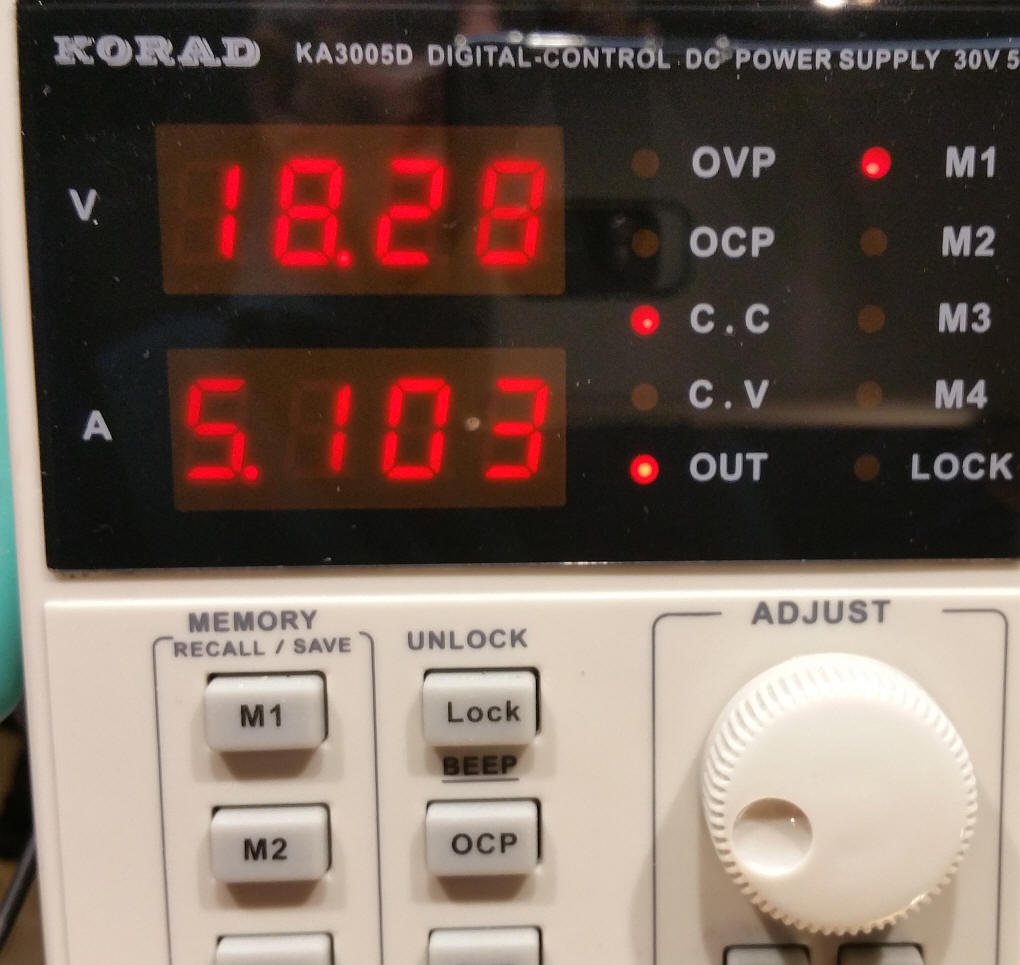
While I am unable to test the H-Bridge to its advertised capacity of 43 amps, I was able to test it to about 4 amps at 18 volts and the heat sink only got to about 70 degrees. I am sure that this unit can provide more than enough power to run even a large layout.
Note that this unit will not run the main track and the programming track as it contains only a single H-Bridge. I would suggest using this for the main track and the 2nd channel of the standard Arduino motor shield for programming.
I tested the H-Bridge when pushed to high power and when shorted. Under both conditions it should shut down. In order to get it to respond properly I changed the value of CURRENT_SAMPLE_MAX in the CurrentMonitor.h tab from 300 to 500.
With that change made I hooked up the system 14 volts DC and observed the following:
| Percent throttle | Percent shown by JMRI current monitor | Amps drawn |
| 40 | 24 | 1.6 |
| 50 | 30 | 1.8 |
| 60 | 33 | 2.1 |
| 70 | 35 | 2.2 |
| 75 | 38 | 2.4 |
| 80 | 40 | 2.5 |
| 90 | 42 | 2.7 |
| 100 | 46 | 2.8 |
A dead short on the motor (not the DCC that would be on the track) shut the throttle down (via DCC++) when power was at 50% throttle or more. A dead short on the DCC that would be on the track shuts down the power immediately - note that this shutdown is performed by the DCC++ controller. The chips in the H-Bridge also have a current limit at which point power will shut down but the lower limit of that value is 33 amps!
If the value of CURRENT_SAMPLE_MAX is less than 500 it would trip at lower throttle settings.
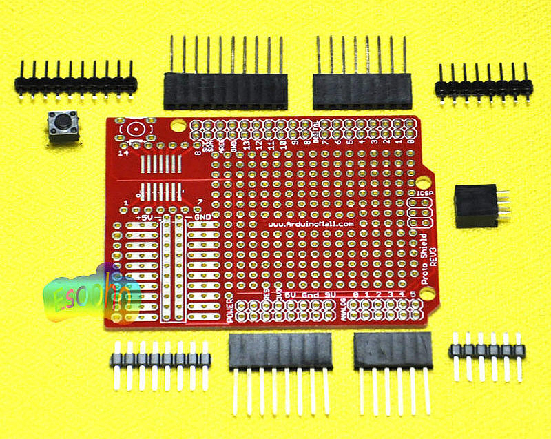
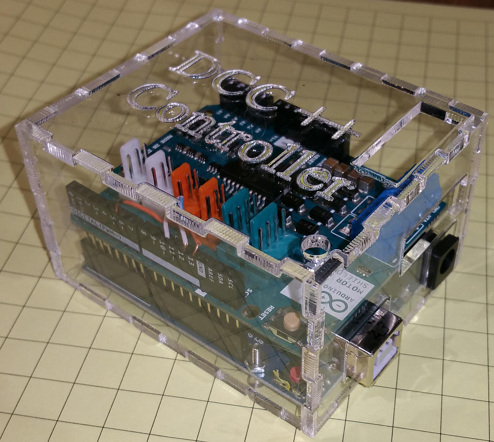
To make use of the 43 amp H-Bridge I added it and the transistor interface to a prototype shield like this one from eBay.
The shield sits atop the standard motor shield that is still used for the programming track connection.
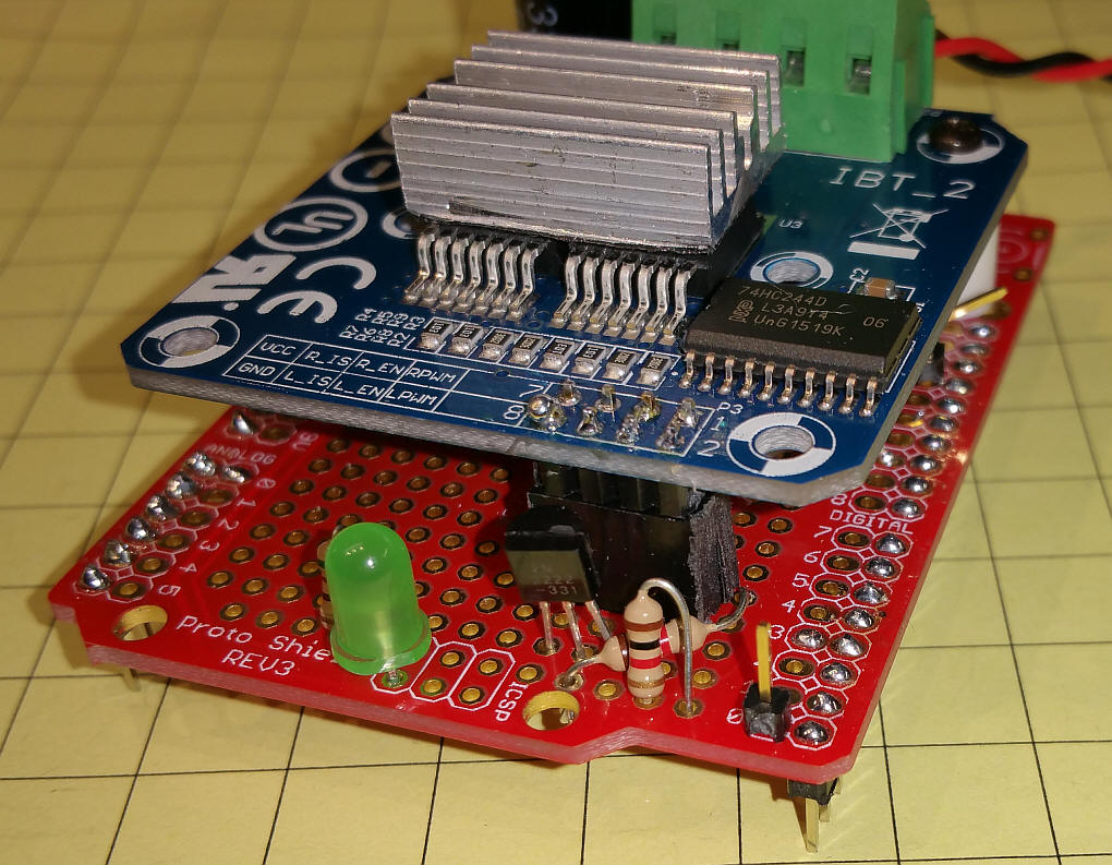
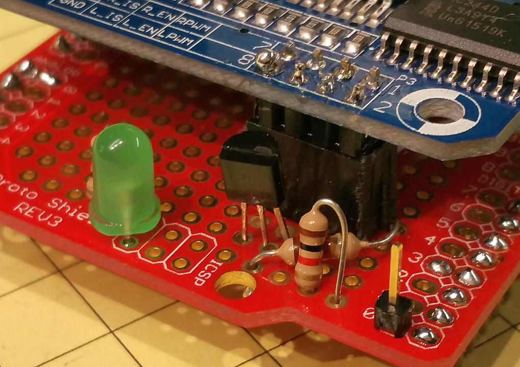
This close-up shows the transistor and two resistors that adapt this H-Bridge to the Arduino's DCC++ circuit.
Here is a bottom view of the shield
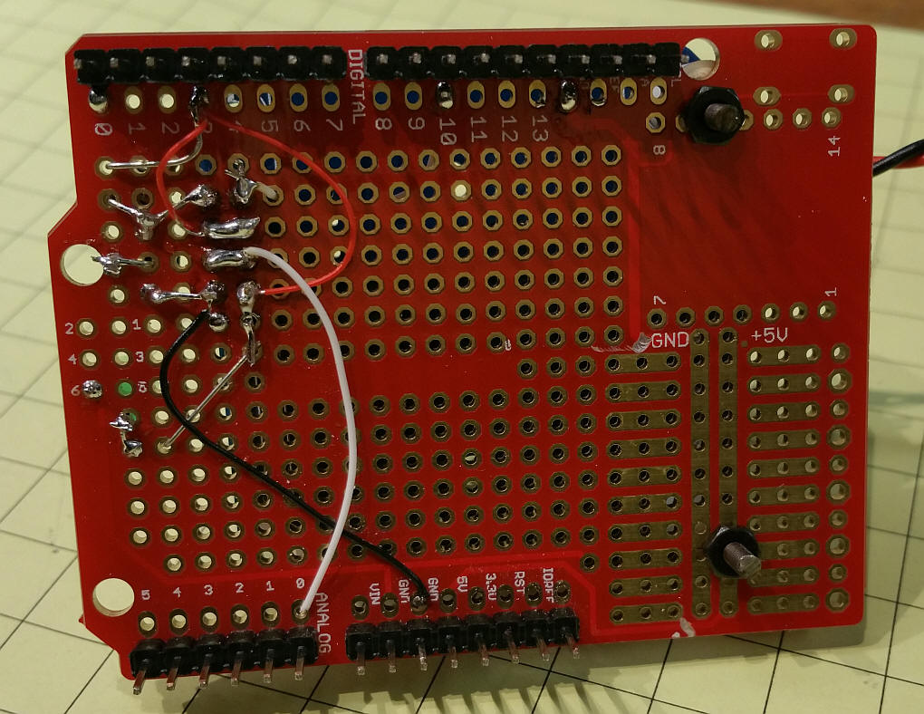
The green LED comes on when power is turned on in JMRI. I removed the 8 pin header and reversed it so that it extends down from the board. That allows an easy plug-in connection to the shield.
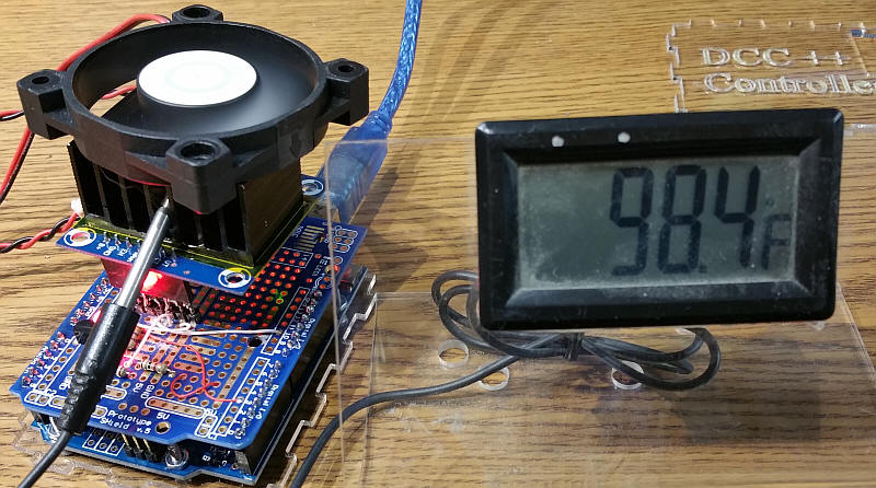
I removed the large heat sink that is normally mounted on the bottom of the circuit board and replaced it with a smaller heat sink that is more than adequate when drawing 5 amps at 18 volts (see next image)
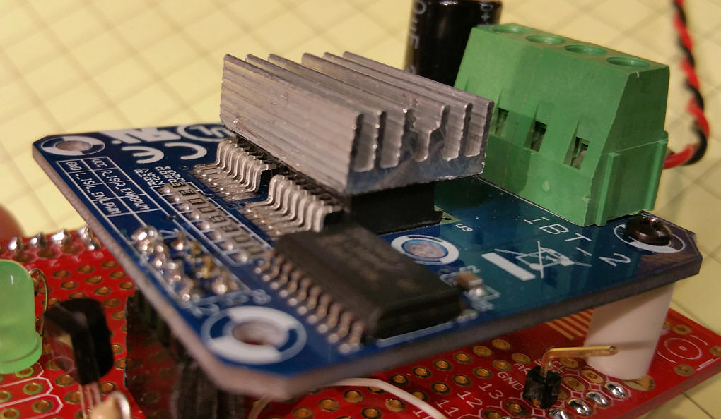
I ran the H-Bridge at 18+ volts and 5+ amps for 20 minutes and measured a temperature of 152 degrees F without any heat sink and 132 degrees F with the small heat sink.
There is some information on the web that suggests that the L298 motor shields that many of us have been using with DCC++ cannot deliver any where near the 2 amps that are claimed and listed on their data sheets.
I tested both an eBay purchased shield and one that I built up from a 5 amp (advertised!) H Bridge.
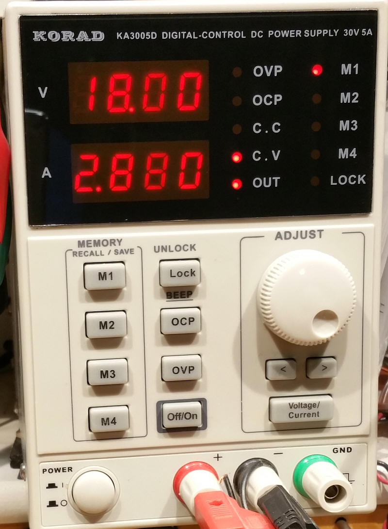
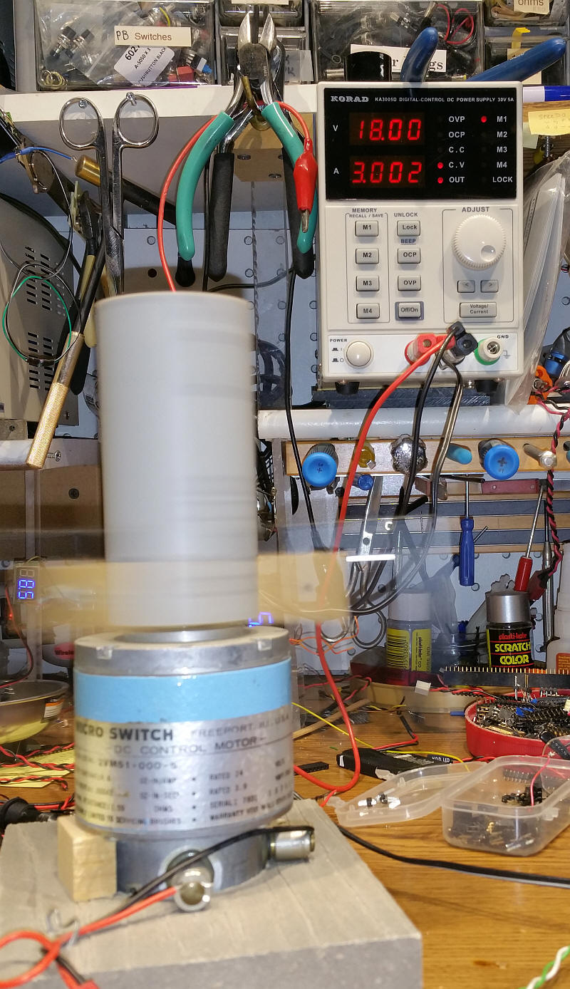
The power supply that I used for the tests is shown here. It can supply up to 5 amps at 30 volts. For all of the tests I set the voltage at 18 volts as that is a common voltage used with HO layouts.
I used a large 24 volt motor as an inductive load for the tests. The DCC controller was an MRC G-Scale rated at 8 amps.
Can be found here: http://www.ebay.com/itm/310787745501?_trksid=p2059210.m2749.l2649&ssPageName=STRK%3AMEBIDX%3AIT
or search eBay for L298P Shield R3 DC Motor Driver Module 2A H-Bridge 2 way For Arduino
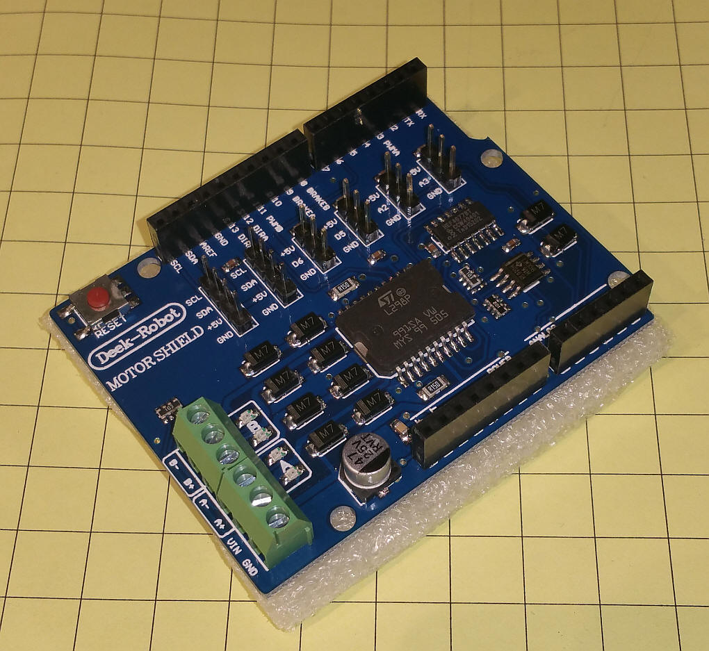
Make sure the shield looks like this - it may or may not have the "Deek Robot" label.
Here is the unit connected to an Arduino Uno
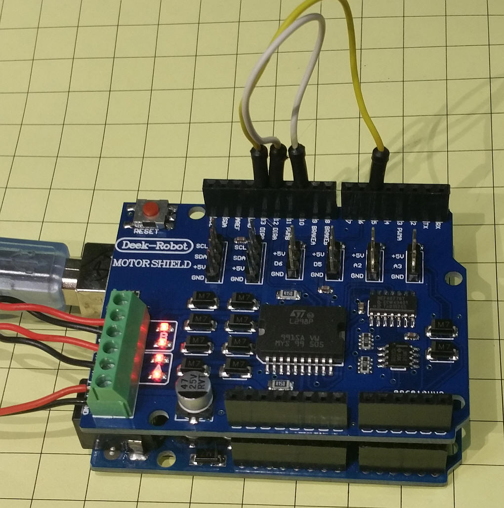
Make sure you jumper pins as shown ( 10-->12 and 5-->13) - you must also cut the trace labeled VIN - this allows you to isolate the voltage that goes to the motor driver from the power on the Uno.
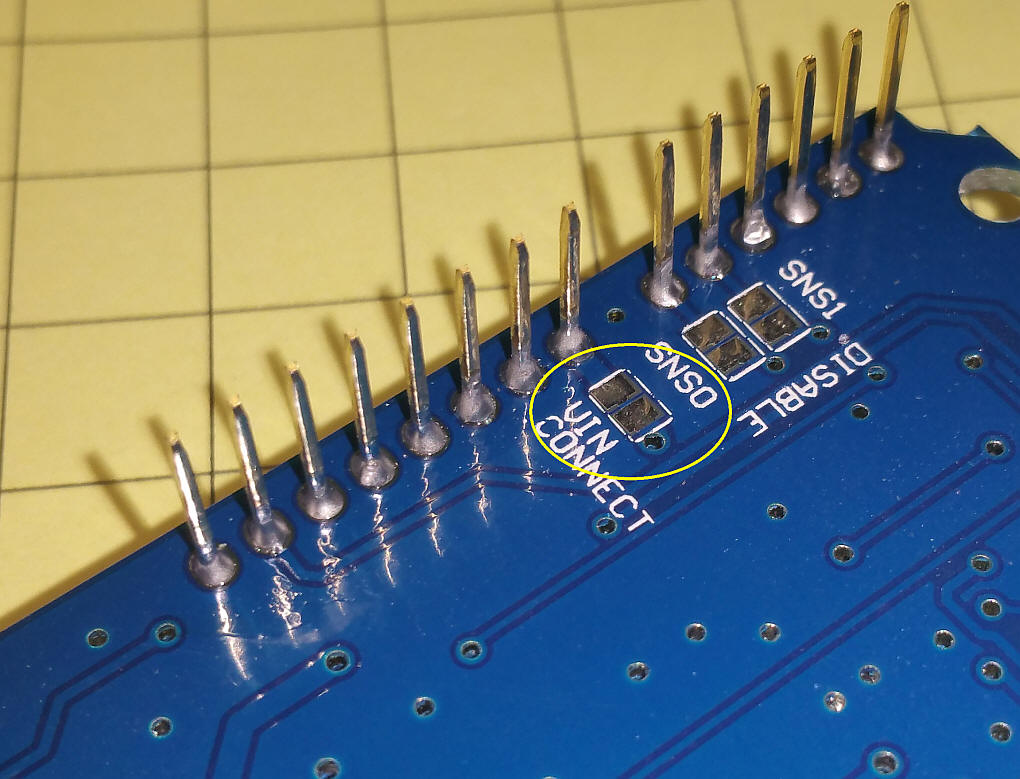
Note the warning on the schematic - you MUST cut the jumper above if you power the motor board with more than 12 volts.
The motor controller shown here can be modified with a simple one transistor / two resistor circuit to work with DCC++. This unit does not provide for a programming track as it is a single H-Bridge - I have ordered several other H-Bridges that have double bridges and may be able to provide both a main and programming track.
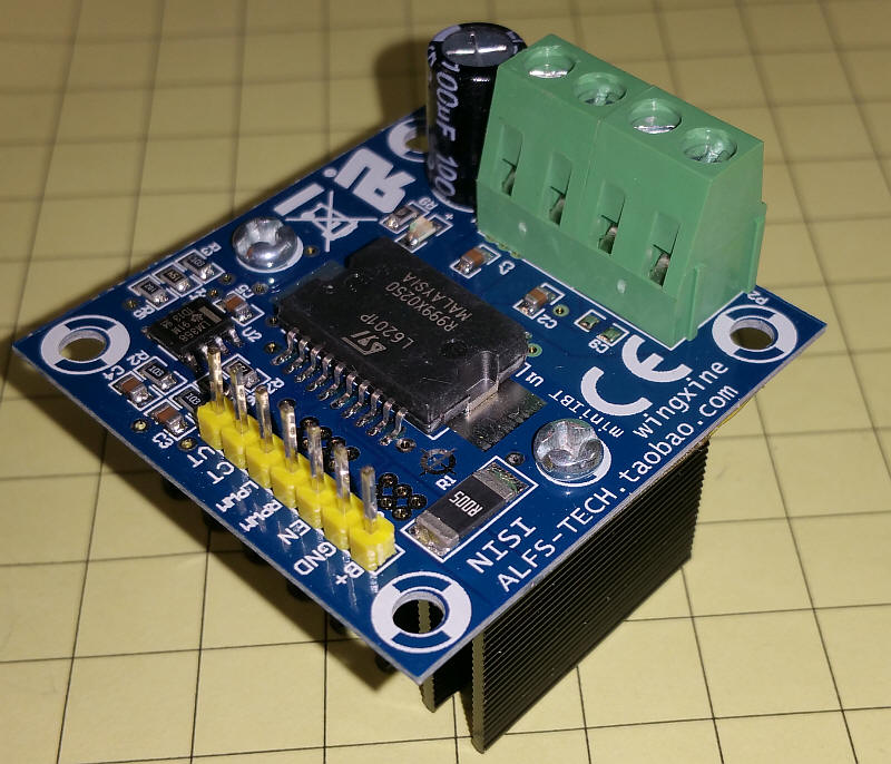
http://www.ebay.com/itm/NEW-Motor-Drive-Module-H-bridge-PWM-0-100-Control-12V-48V-5A-NMOS-structrue-/131683064430?hash=item1ea8ec1a6e:g:ft8AAOSwHPlWehjf or search eBay for: Motor Drive Module H-bridge 5a
These are available from China for about $12 including shipping.
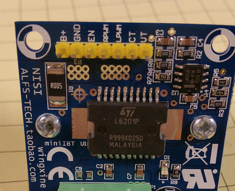
The specs on the power chip are here: http://www.mouser.com/ds/2/389/CD00000089-249756.pdf The L6201P is rated for 5 amps.
The 7 pin header connects to the Arduino. The B+ pin and VT pin are not used. Ground goes to ground, EN (enable) goes to digital pin 3 on the Arduino and RPWM and LPWM connect to pin 10 on the Arduino and the simple toggling circuit. The CT (Current sense) pin goes to analog pin A0 on the Arduino.
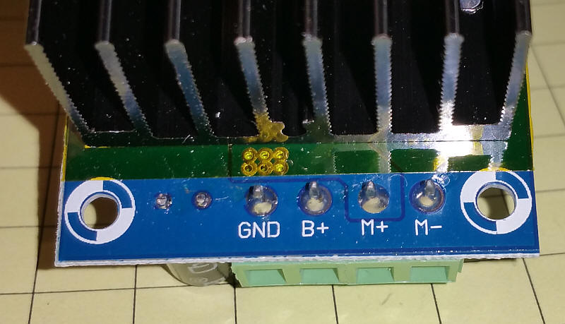
DC power for the unit goes to two of the large, screw terminals labeled GND and B+. Track goes to screw terminal M+ and M-.
Because this motor control board uses two PWM input pins a simple circuit is needed to adapt it to the standard DCC++ Arduino.
This photo shows the test load motor and the power supply putting out 18 volts at 3.002 amps.
When drawing 3 amps the current meter in JMRI shows about 66%. Note that the CURRENT_SAMPLE_MAX variable in the CurrentMonitor.h tab was changed from 300 to 900. When it was at 300 the system shut down when pulling just over 1 amp.
I used a temperature probe to measure the temperature of the heat sink. The chip itself was much hotter than the heat sink.
I performed a number of tests on the eBay shield (rated at 2 amps) and with the 5 amp unit that I built up from an eBay H-Bridge. The results are below. I also tested a genuine Arduino Motor Shield and got almost the same results that I found with the eBay clone.
Ambient temperature about 65°F.
| bare chip | heat sink | heat sink & fan | Notes: | |
| eBay Motor Shield 18 volts / 1 amp | 190°F thermal shutdown | 180°F thermal shutdown | 90°F stable | #define CURRENT_SAMPLE_MAX 600 |
| eBay Motor Shield 18 volts / 1.25 amp | 98°F stable | |||
| eBay Motor Shield 18 volts / 1.5 amp | 101°F shutdown / restart | |||
| 5 Amp - eBay 18 v, 2 amps | (heat sink included - no test without it) | 168°F thermal shutdown / restart | 79°F stable |
#define CURRENT_SAMPLE_MAX 900 Thermal shutdown at internal temperature of 150°C (302°F) |
| 5 Amp - eBay 18 v, 3 amps | 90°F stable | |||
| 5 Amp - eBay 18 v, 3.3 amps | 95°F shutdown / restart |
Conclusions - while these tests were rather unscientific some conclusions can be made. Neither of the test units came anywhere near their rated performance. The bare eBay shield is only good for something less than 1 amp power draw at 18 volts DC input. Adding a heat sink and fan to the top of the L298 increases the power capability to about 1.25 amp @ 18 volts.
The 5 amp unit, with a fan and heat sink, performed well. It was stable at 3 amps at 18 volts and only shutdown when power went to around 3.3 amps.
Adding a small fan that is directed to the heat sink dropped the temperature of the heat sink significantly and should be considered for most installations. I used a small CPU fan from an old desktop computer.
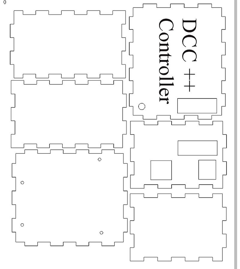
The Corel Draw file is here: DCC_Arduino/DCC++/DCC++BoxV-2-2.cdr It was done in Corel Draw version X6
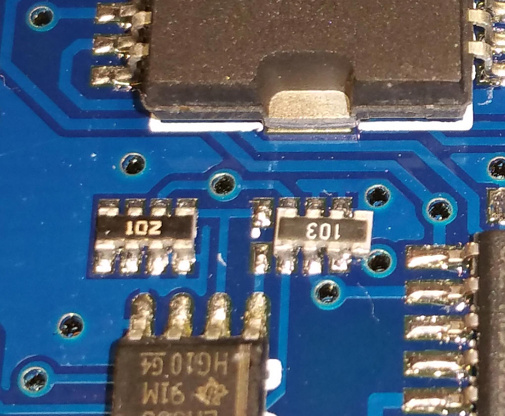
I purchased two of the eBay shields that are described above. The first one worked like a charm. I tried the second board and each time I turned the power on the four power LEDs blinked briefly then went out.
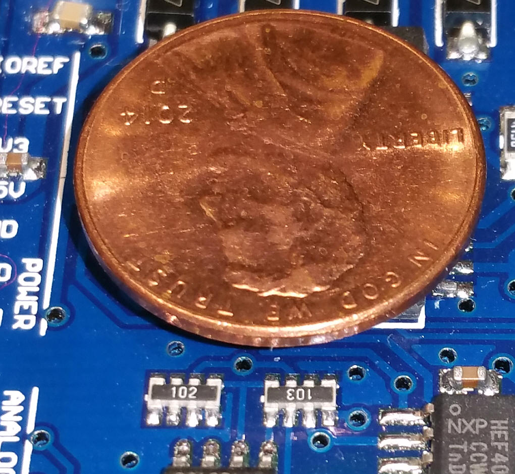
I spent some time perusing the board and spotted the error in construction below. Can you see it, too? The 10K resistor array labeled "103" is shifted one set of pins to the right.
I figured that it could be the problem and carefully removed the (really tiny!) component and promptly lost it when the spring loaded tweezers I was using went SPRONG - I am sure it is somewhere in my workshop but I don't know where!
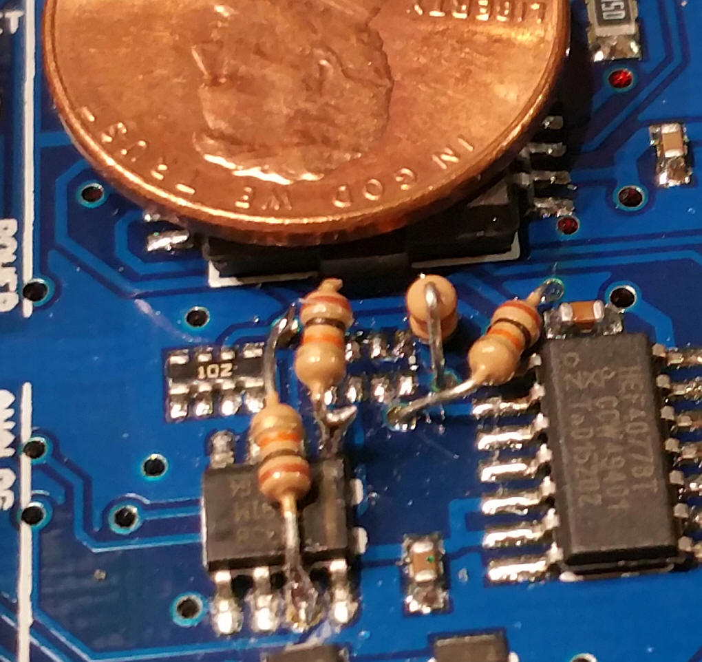
Rather than throw in the towel I traced the connections to the array and used four 1/8 watt resistors to take the place of the array. The (no so pretty) repair is shown below. The really good news is that now it works!
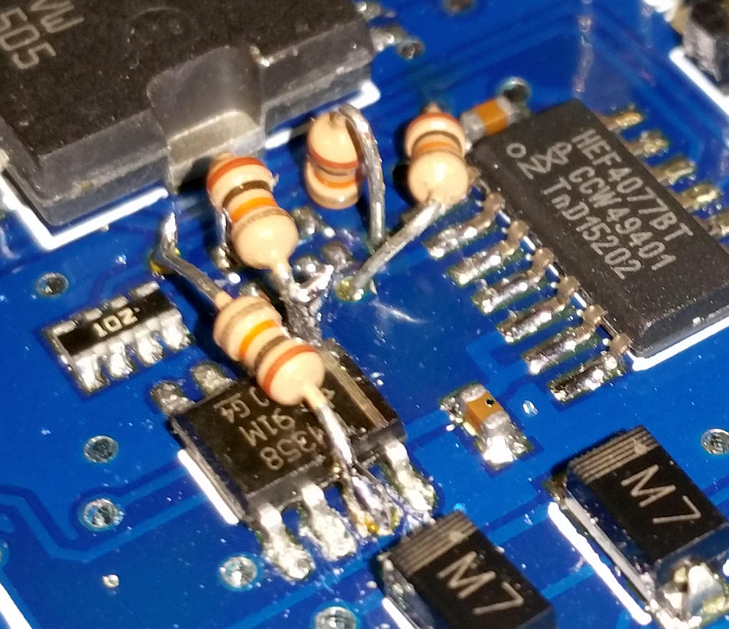
Here are two photos that show the small area that I had to work in - great fun!