| Introduction I designed and built a high amperage DCC booster a few years ago - see: Original Booster This has been a very popular project for many model railroaders with the YouTube video having well over 10,000 views. The original circuit utilized a circuit board that was designed for another DCC project and was not ideally suited for this booster. With so much interest in the booster I decided to update it to make assembly easier and to add to its functionality. The primary objectives for the revision are:
Hopefully this will allow more hobbyists to build and use the booster. |
| Circuit The circuit is shown below. The main differences from the original board are the addition of a second pot to set temperature and a DS18B20 temperature sensor.
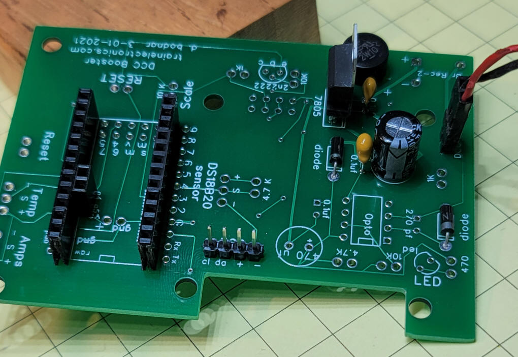
In the bottom left corner of the circuit board below there are two areas where bridge rectifiers can be placed. You can use either one but do not need to use both.
|
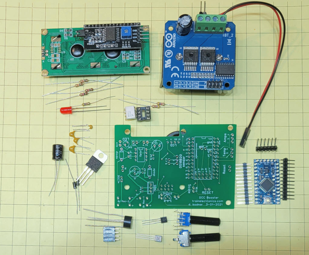
| Parts Most parts are available from eBay or Amazon:
|
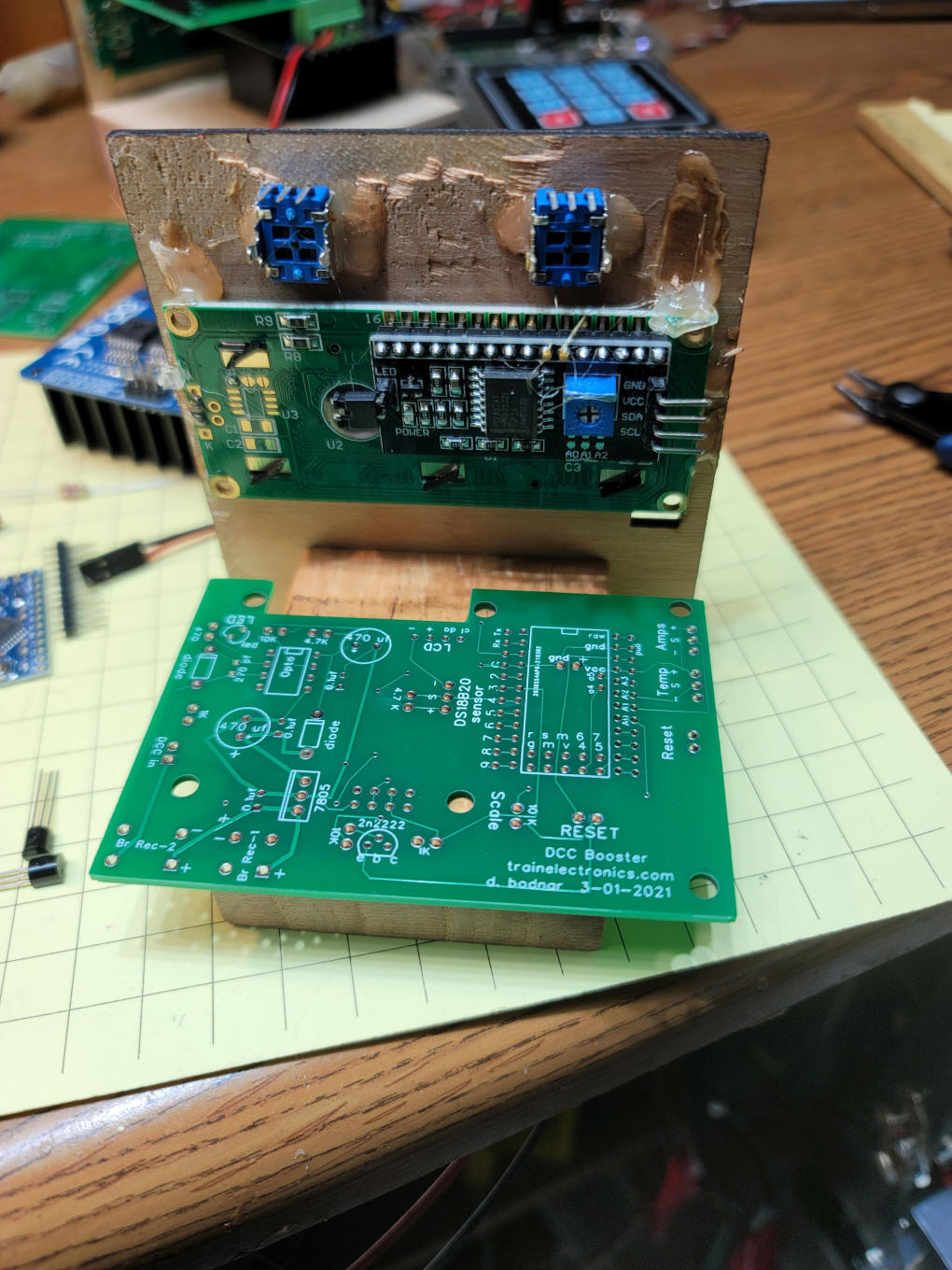
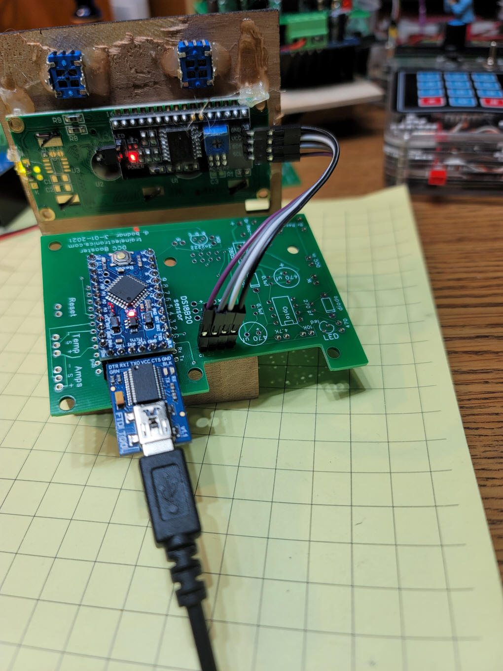
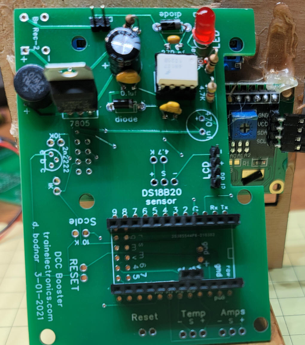
| Building the Booster These photos should help you to build the booster The back of the mounting frame is shown here. The LCD display and two potentiometers are shown.
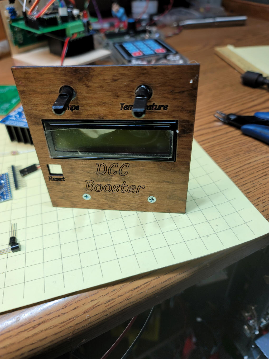
This is the front view. The "Reset"
button is optional and not shown in this photo
Once the socket for the Arduino is mounted and the LCD connections are made you can test programming the Arduino. At the bottom of the photo you can see the FTDI adapter that is needed to program the Arduino. These programmers are available from Amazon, with or without the Arduino.
Be sure to include the two pin header on the back of the Arduino and ...
...on the circuit board. The power supply part of the circuit has
been installed here. The socket that is used with
the Arduino is shown on the left.
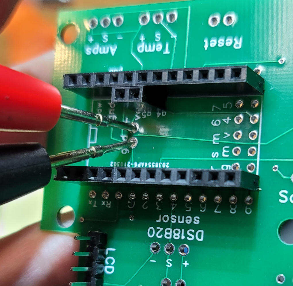
To test the voltage section apply 12 or so
volts DC to the DCC input pins - use a volt meter to test the
voltage at the test points shown below.
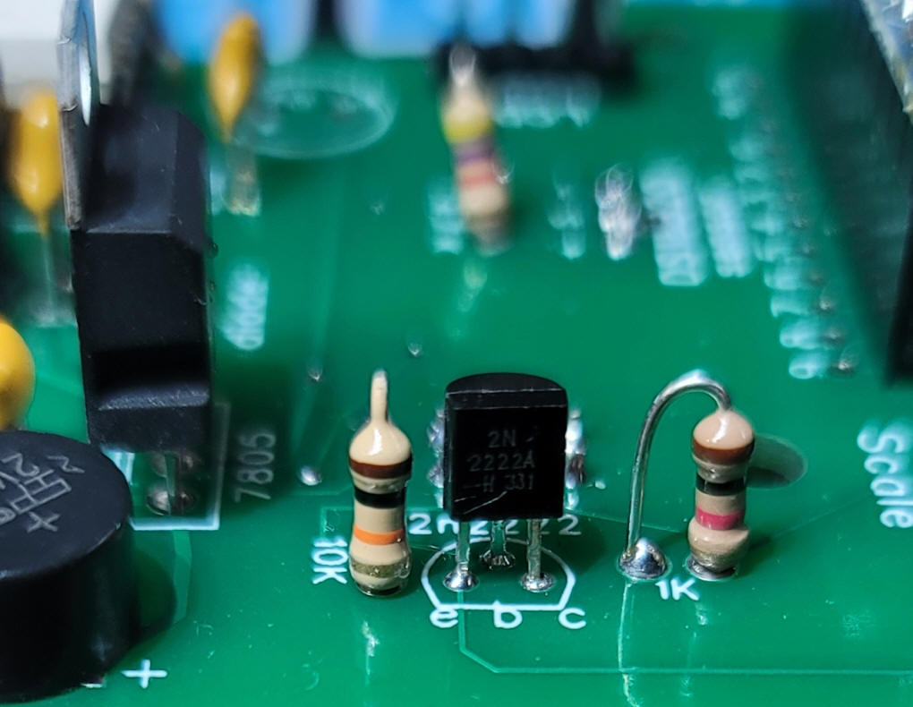
Next complete the rest of the DCC input circuitry., You should not need to use the 2nd 470 uF capacitor (left center)
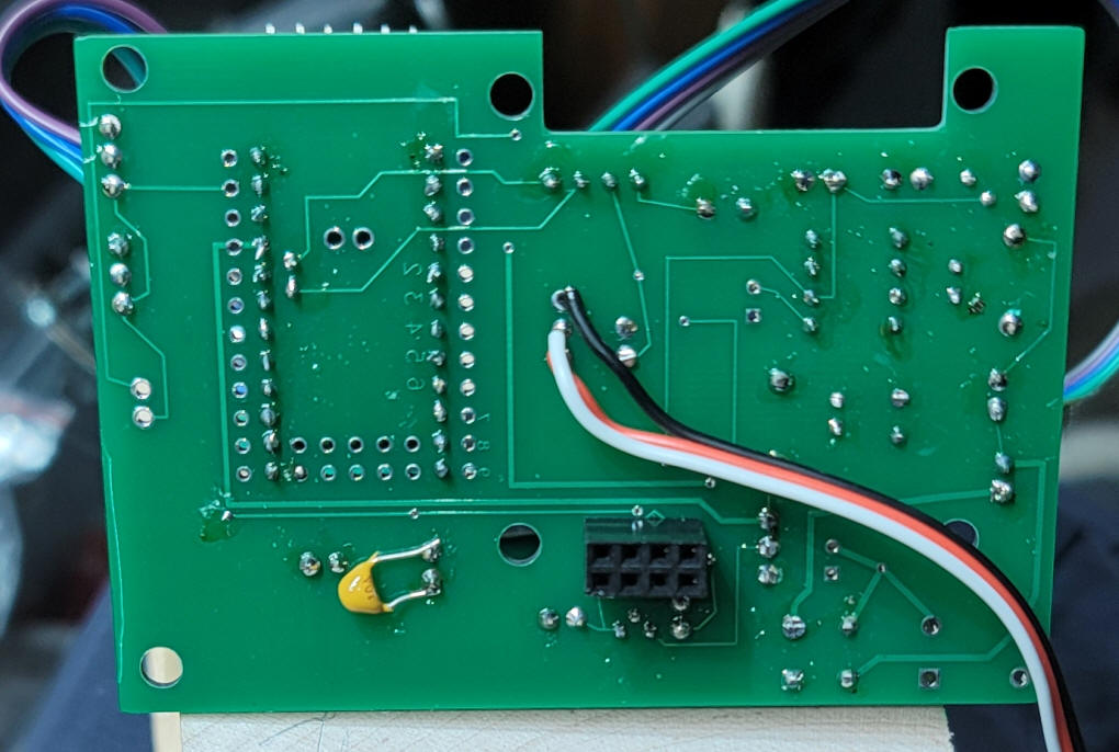
The transistor inverter and IBT-2 socket need to be added. Be sure to mount the 8 pin socket from the BACK of the board!
Here you can see the 8 pin socket on the
back of the board. This also shows that the temperature sensor
(DS18B20) is also mounted from the back.
|
| H-Bridge Observations I have purchased the IBT_2 H-Bridges from a number of vendors on eBay and Amazon. While most of them worked well I did get two that were intermittent at best. If you have trouble getting the booster to work the first thing I would suggest is swapping IBT_2 units making sure to use a replacement from a different source. The other observation for the IBT_2 it that it really does not need the huge heat sink that is attached to it. First of all, I would hope that most of us would use this booster for no more than 5-10 amps. At this power level the board does not get very hot. If you do plan on using the heat sink first remove it and add heat sink compound between the board and heat sink. This will make the heat sink work much better. I checked all of the IBT_2 boards that I purchased and NONE of the had heat sink grease on them. |
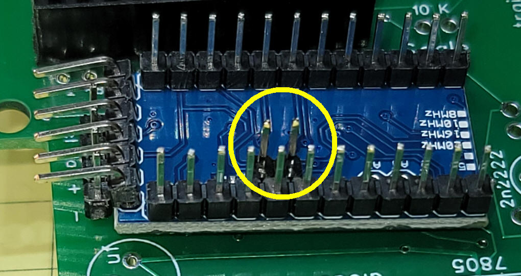
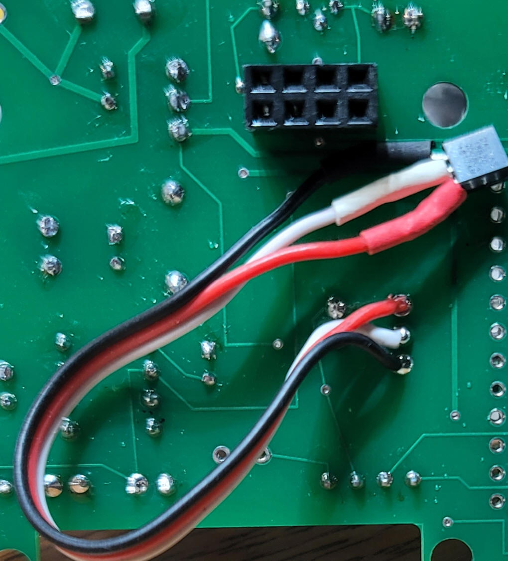
| Current Sense Modification The IBT-2 can provide information on how much current is being used by the DCC booster system. After some experimentation I found that a 10K scaling resistor is needed to pull pin A0 low. In addition a small capacitor (0.1uF worked well for me ) smoothes out the current reading. This was discovered after the boards were fabricated so space for this capacitor is not provided on the board. I chose to place it on the back of the board across the current sense resistor as shown here:
|
| Using the Booster Connect the power input on the IBT_2 (marked B+ and B- on the bottom of the board) to a 12-20 volt DC power supply. Connect the other IBT_2 screw terminals (marked M+ and M- on the bottom of the board) to the track to be powered. It does not matter which rail each wire connects to. Connect the 8 pin male header on the IBT_2 to the 8 pin female
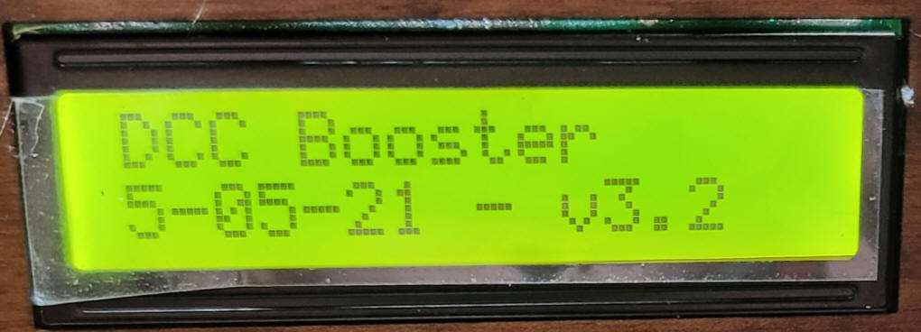
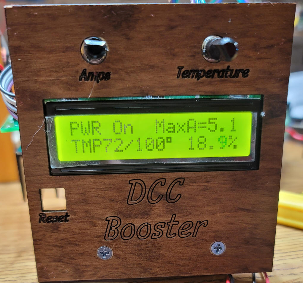
header on the bottom of the main circuit board. Connect the DCC connection on your DCC system to the two pins on the main board marked DCC in. Turn on the DCC system that feeds the DCC in on the booster board. The display should light up and show a version number and other information. If you cannot see the text you may need to adjust the small blue potentiometer on the back of the display board.
Use the AMPS potentiometer to set the amp reading that will trigger the system to turn off. It will remain off for 5 seconds.. If you want to change this find the void turnPowerOff() {
sub-routine and change the delay(5000); line to another value - you could also have it stay off indefinitely needing a reset to restart. Use the TEMPERATURE potentiometer to set the temperature that will trigger the system to turn off. I generally set this to 20 or 30 degrees above the ambient temperature.
|
| Arduino Code The code for the booster is below. Version: DCC_Booster_NEW_Board-v3-2 Please note that there are several libraries that must be included. /* As posted on web page - uses modified board DCC Booster using the 43 amp H-Bridge from eBay & Amazon */ #include <OneWire.h> #include <DallasTemperature.h> #define ONE_WIRE_BUS 4 OneWire oneWire(ONE_WIRE_BUS); DallasTemperature sensors(&oneWire); DeviceAddress insideThermometer; #include<EEPROM.h> int LED = 13; // LED to blink when DCC packets are sent in loop int PowerOn = 3; // pin to turn booster on/off int Pot1 = 1; // max current pot int Pot2 = 2; // max temperature pot float PotReading = 0; float TmpPotReading = 0; int CurrentPin = 0; int CurrentPinReading = 0; int SetPotFlag = 0; float version = 3.2; #include <Wire.h> #include <LCD.h> #include <LiquidCrystal_I2C.h> #define I2C_ADDR 0x27 // <<----- Add your address here. Find it from I2C Scanner #define BACKLIGHT_PIN 3 #define En_pin 2 #define Rw_pin 1 #define Rs_pin 0 #define D4_pin 4 #define D5_pin 5 #define D6_pin 6 #define D7_pin 7 LiquidCrystal_I2C lcd(I2C_ADDR, En_pin, Rw_pin, Rs_pin, D4_pin, D5_pin, D6_pin, D7_pin); unsigned long time; unsigned long now; long cAverage = 0; int avgTimes = 400; int lastAverage = 0; int resetFlag = 0; float percentage = 0; int temp1 = 0; float tempC = 0; int CurrentAdjustValue = 300; // adjust based on current Scale resistor value void setup() {
delay(500);
pinMode(LED, OUTPUT);
pinMode(PowerOn, OUTPUT );
lcd.begin (16, 2); // LCD is 16 characters x 2 lines
lcd.setBacklightPin(BACKLIGHT_PIN, POSITIVE);
lcd.setBacklight(HIGH); // Switch on the backlight
lcd.home (); // go home
Serial.begin (115200);
lcd.setCursor(0, 0);
lcd.print("DCC Booster");
lcd.setCursor(0, 1);
lcd.print("5-05-21 - v");
lcd.print(version, 1);
Serial.print("5-09-2021 version "); Serial.println(version, 1);
delay(1000);
lcd.clear();
delay(500);
now = millis();
Serial.print("Locating devices...");
sensors.begin();
Serial.print("Found ");
Serial.print(sensors.getDeviceCount(), DEC);
Serial.println(" devices.");
Serial.print("Parasite power is: ");
if (sensors.isParasitePowerMode()) Serial.println("ON");
else Serial.println("OFF");
if (!sensors.getAddress(insideThermometer, 0)) Serial.println("Unable to find address for Device 0");
Serial.print("Device 0 Address: ");
printAddress(insideThermometer);
Serial.println();
// set the resolution to 9 bit (Each Dallas/Maxim device is capable of several different resolutions)
sensors.setResolution(insideThermometer, 9);
Serial.print("Device 0 Resolution: ");
Serial.print(sensors.getResolution(insideThermometer), DEC);
Serial.println();
}
// NOTE:  about 0.014 amps / digit of reading with 10K resistor on sense line
void loop() {
  sensors.requestTemperatures(); // Send the command to get temperatures
  printTemperature(insideThermometer); // Use a simple function to print out the data
  PotReading = analogRead(Pot1);
  PotReading = PotReading / 100;
  TmpPotReading = analogRead(Pot2);
  TmpPotReading = TmpPotReading / 10;
  lcd.setCursor(0, 1);
  lcd.print("TMP");
  lcd.print (DallasTemperature::toFahrenheit(tempC), 0); // Converts tempC to Fahrenheit
  int temptemp = (DallasTemperature::toFahrenheit(tempC));
  lcd.print("/");
  lcd.print(TmpPotReading + 100, 0);
  lcd.print((char)223);
  lcd.print(" ");
  if (temptemp > TmpPotReading + 100) {
    Serial.println("TEMPERATURE FAULT ! ! !");
    lcd.setCursor(0, 1);     lcd.print("T FAULT!");
  }
  lcd.setCursor(8, 0);
  lcd.print("MaxA=");
  lcd.print(PotReading, 1);
  showPercentage();
  resetFlag++;
  if (resetFlag >= 100) {
    resetFlag = 0;
  }
  cAverage = 0;
  for (int xx = 0; xx < avgTimes ; xx++) {
    //CurrentPinReading = analogRead(CurrentPin);
    if (CurrentPinReading >= 1000) {
      Serial.print("Value = "); Serial.print(CurrentPinReading);
      Serial.println("   STOPPPPPPPPPPPPPPPPPPPPPPING");
      turnPowerOff();
    }
    CurrentPinReading = analogRead(CurrentPin);
    cAverage = cAverage + CurrentPinReading;
  }
  CurrentPinReading = cAverage / avgTimes;
  Serial.print("raw current ");  Serial.print(CurrentPinReading);
  turnPowerOn();
  lastAverage = CurrentPinReading; // keep for compare & print
  Serial.print("   Current = ");   Serial.println(CurrentPinReading - CurrentAdjustValue); // gives near zero with filter & 100K pull down
}  //END LOOP
void showPercentage() {
  percentage = (CurrentPinReading - CurrentAdjustValue ) / PotReading; // was 0.014
  percentage = percentage * 2;
  if (percentage < -0) {
    percentage = 0;
  }
  if (millis() - now >= 500)   // only update LCD every 1/2 second to limit flicker
  {
    lcd.setCursor(11, 1);
    lcd.print(percentage, 1);
    lcd.print("%  ");
    now = millis();
  }
  if (percentage > 100) turnPowerOff();
}
void turnPowerOff() {
  digitalWrite(PowerOn, LOW);
  lcd.setCursor(0, 0);
  lcd.print("OFF-5sec");
  delay(5000);
  turnPowerOn();
  lcd.setCursor(0, 0);
  lcd.print("               ");
}
void turnPowerOn() {
  digitalWrite(PowerOn, HIGH);
  lcd.setCursor(0, 0);
  lcd.print("PWR On");
}
void printTemperature(DeviceAddress deviceAddress) {
  tempC = sensors.getTempC(deviceAddress);
  if (tempC == DEVICE_DISCONNECTED_C)
  {
    Serial.println("Error: Could not read temperature data");
    return;
  }
  Serial.print("Temp C: "); Serial.print(tempC); Serial.print(" Temp F: "); Serial.println(DallasTemperature::toFahrenheit(tempC)); // Converts tempC to Fahrenheit
}
// function to print a device address
void printAddress(DeviceAddress deviceAddress)
{
  for (uint8_t i = 0; i < 8; i++)
  {
    if (deviceAddress[i] < 16) Serial.print("0");
    Serial.print(deviceAddress[i], HEX);
  }
}
|