Arduino DCC Function Decoder
Revised 10-07-14
click here for new software
A video is on YouTube here:
https://www.youtube.com/watch?v=WWlZJH2KPUQ
A video with the newest software is here:
http://youtu.be/oI-NjCDbUXo
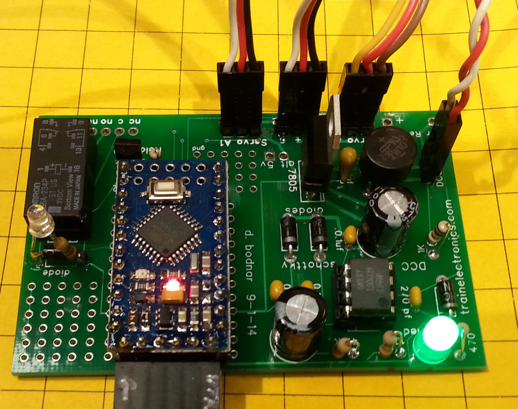
| You may have noted that I used a source of
external power (a cell phone battery) to power the servos in the
video. I did that as the system was shutting down when I tried to
operate two or three servos. It turns out that the problem was not
with the circuit or the servos but with the DCC system that I was
using for testing. It is composed of a laptop running
JMRI
and a
SPROG II controller. The SPROG was the problem*. It must have a very sensitive shutdown circuit that detected too much power being drawn. When I tried 3 servos using the board's power supply with another DCC system and with the SPROG II and a 3 amp DCC booster it worked perfectly.
|
| Introduction Recently I have been experimenting with building DCC controllers and decoders based on Arduino microcontrollers. My notes on these projects are here Arduino DCC Decoder and here Arduino DCC Controller. After hand wiring several of the DCC decoders I decided that a circuit board would make things much more convenient for me and other hobbyists. I designed a board that would provide these features:
|
|
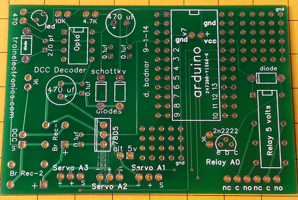
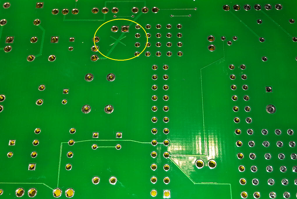
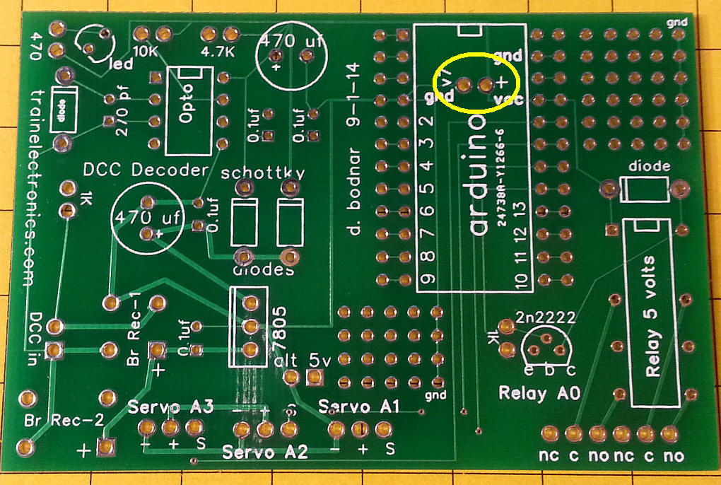
Schematic The DCC power goes to the optocoupler via a 1K resistor and to the 7805 voltage regulator. The 5 volt output from the 7805 if filtered before it goes to the optocoupler and Arduino. More filtration options than may be necessary are provided. My tests have had the board working reliably with D2 and C5 omitted. I also used 4.7 uf Tantalum caps for C1 as they do an excellent job of cleaning up the DC. There is an "X" on the back of the circuit board (shown below). If you want to provide a supplementary soruce of 5 volts to operate the servos cut the trace and supply the power to the two pins marked "alt 5v". I have had problems with the unit resetting itself when I ran two or three servos from the on-board power supply. Cutting the trace and adding an external power connection cleared everything up. The relay is a DPDT, 5 volt relay. It
is turned on and off through pin A0. The three servos are
connected to pins A1, A2 and A3 on the Arduino.
|
|
Circuit Board The Gerber files for this board are here: DCC_Decoder_Board.zip The board was designed using FreePCB - the fpc file is included in the ZIP file. The top of the circuit board is silk screened to show where to install components.
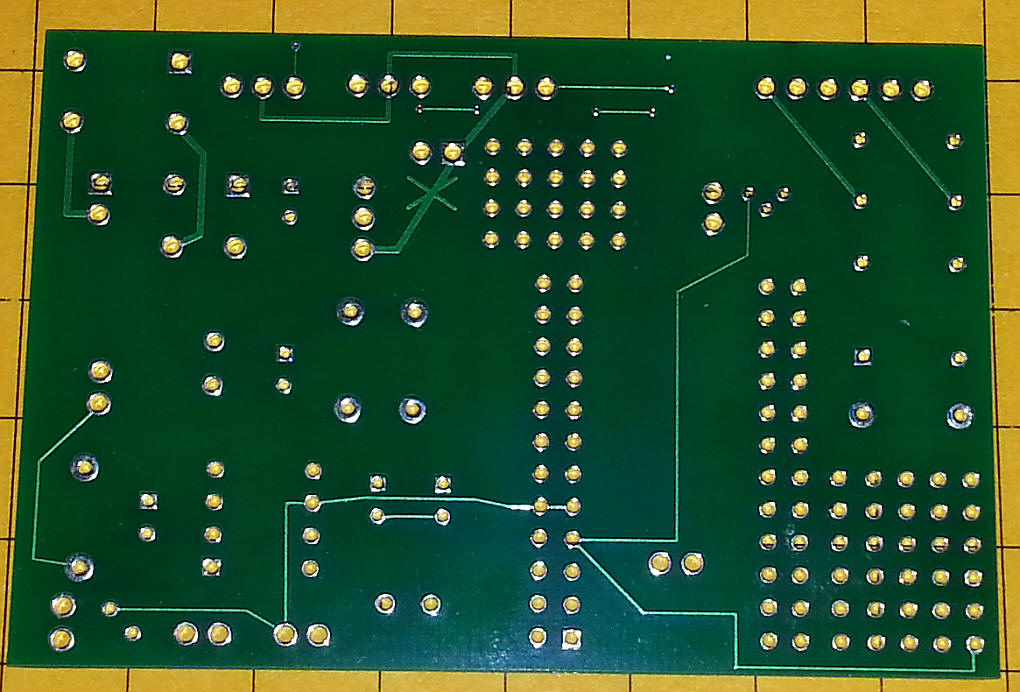
The back of the board is shown here:
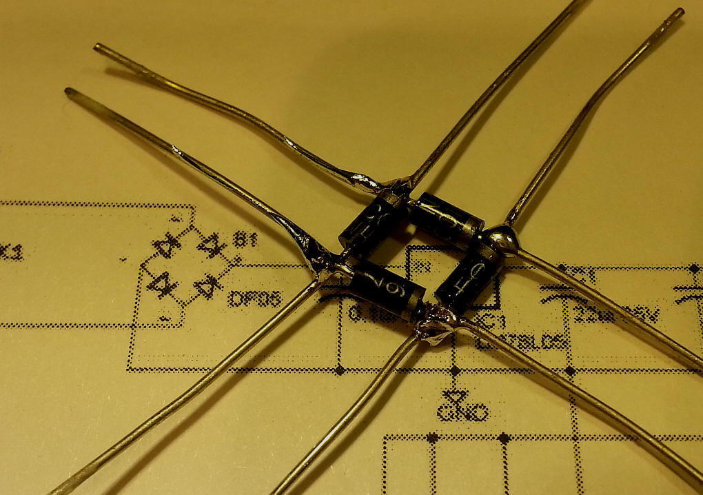
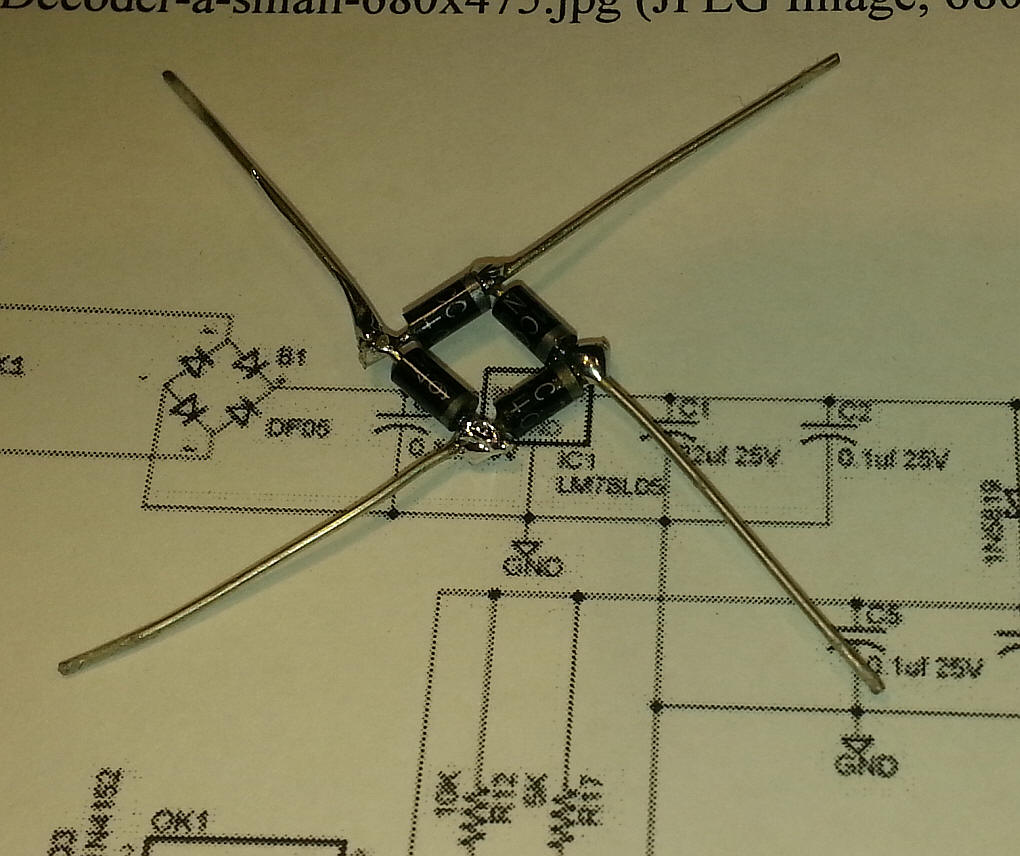
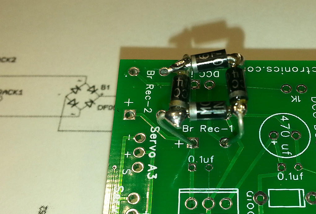
You can install either of two bridge rectifier styles - this photo shows both on the board - you only need ONE of them, either the small through hole unit in the lower left or the round one with long leads above it. If you don't have either of the suggested bridge rectifiers you can easily make your own with four 1 amp diodes (1N4007 or similar) as shown here. Take care to align the bands as shown.
Cut off every other lead.
Insert in the circuit board as shown.
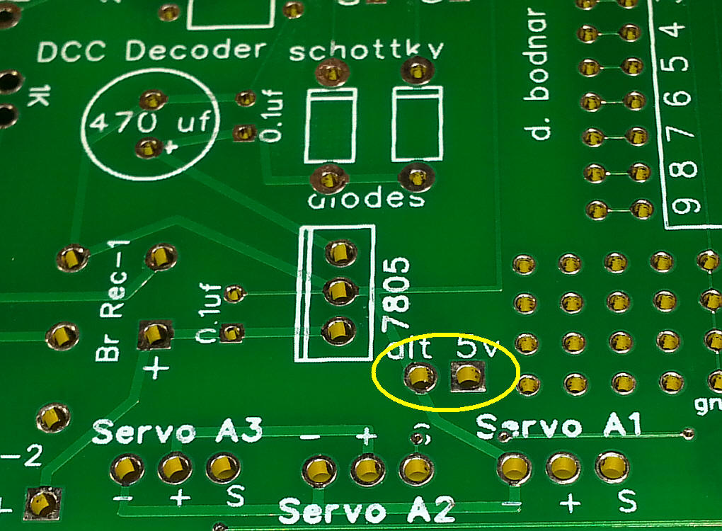
The servos are normally powered from the 7805 voltage regulator on the board. If you are using large servos more power may be needed for them. To use an external source of 5 volts cut the trace shown here.
External power for the servos (5 volts, only!) is applied to the two terminals circled in yellow. Positive on the right and negative on the left.
There is also a set of holes under the Arduino that can be used for additional filtering. An electrolytic or non-electrolytic cap can be added there if needed. The holes are circled in yellow in this photo. Note that the hole on the right is positive should you use an electrolytic cap.
|
Software DCC_3_Servos_1_Relay_v4 9-26-14 This version moves as many as three servos and controls one relay Servo A3 - Pressing F1 moves to Clockwise extreme, Pressing F4 modes to Counterclockwise extreme Servo A2 - Pressing F2 moves to Clockwise extreme, Pressing F5 modes to Counterclockwise extreme Servo A1 - Pressing F3 moves to Clockwise extreme, Pressing F6 modes to Counterclockwise extreme Relay - toggle with F11 /*
Ver 4 - working well with variables preset to 0 and 160
next step it to try to change variables with other fn keys
3 servos / 1 relay
use the following to operate servos from DCC controller keypad
F1 & F4 operate Servo 3
F2 & F5 operate Servo 2
F3 & F6 operate Servo 1
toggle relay with F11
*/
#include <NmraDcc.h>
#include <SoftwareSerial.h>
//for serial port on USB
byte rxPin = 0;
byte txPin = 1;
SoftwareSerial mySerial = SoftwareSerial(rxPin, txPin);
// Working 14 Function DCC Decoder DccAckPin not needed
int tim_delay = 500;
#define numleds 16 //using 17th as servo control pin (A3)
#include <Servo.h>
Servo myservo; // create servo object to control a servo
// a maximum of eight servo objects can be created
Servo myservo2;
Servo myservo3;
int pos1=90; // variables to store the servo position
int pos2=90;
int pos3=90;
int pos1CW = 10; // variables to store Clockwise & Counter Clockwise positions
int pos1CCW = 160; // for all three servos
int pos2CW = 10;
int pos2CCW = 160;
int pos3CW = 10;
int pos3CCW = 160;
byte ledpins [] = {
0,3,4,5,6,7,8,9,10,11,12,13,14,15,16,17,18,19};
const int FunctionPin0 = 3;
const int FunctionPin1 = 4;
const int FunctionPin2 = 5;
const int FunctionPin3 = 6;
const int FunctionPin4 = 7;
const int FunctionPin5 = 8;
const int FunctionPin6 = 9;
const int FunctionPin7 = 10;
const int FunctionPin8 = 11;
const int FunctionPin9 = 12;
const int FunctionPin10 = 13;
const int FunctionPin11 = 14; //A0
const int FunctionPin12 = 15; //A1
const int FunctionPin13 = 16; //A2
const int FunctionPin14 = 17; //A3
const int FunctionPin15 = 18; //A4
const int FunctionPin16 = 19; //A5
NmraDcc Dcc ;
DCC_MSG Packet ;
#define This_Decoder_Address 17
extern uint8_t Decoder_Address = This_Decoder_Address;
struct CVPair
{
uint16_t CV;
uint8_t Value;
};
CVPair FactoryDefaultCVs [] =
{
{
CV_MULTIFUNCTION_PRIMARY_ADDRESS, This_Decoder_Address }
,
{
CV_ACCESSORY_DECODER_ADDRESS_MSB, 0 }
,
{
CV_MULTIFUNCTION_EXTENDED_ADDRESS_MSB, 0 }
,
{
CV_MULTIFUNCTION_EXTENDED_ADDRESS_LSB, 0 }
,
};
uint8_t FactoryDefaultCVIndex = 0;
void notifyCVResetFactoryDefault()
{
// Make FactoryDefaultCVIndex non-zero and equal to num CV's to be reset
// to flag to the loop() function that a reset to Factory Defaults needs to be done
FactoryDefaultCVIndex = sizeof(FactoryDefaultCVs)/sizeof(CVPair);
};
void setup()
{
myservo.attach(A3); // attaches the servo on pin A3 to the servo object
myservo2.attach(A2);
myservo3.attach(A1);
pinMode(rxPin, INPUT);
pinMode(txPin, OUTPUT);
mySerial.begin(9600);
mySerial.println("DCC_3_Servos_1_Relay_v4 9-26-14 ");
// initialize the digital pins as an outputs
for (int i=1; i<= numleds; i++) {
pinMode(ledpins[i], OUTPUT);
digitalWrite(ledpins[i], LOW);
}
for (int i=1; i<= numleds; i++) {
digitalWrite(ledpins[i], HIGH);
// delay (tim_delay/10);
}
delay( tim_delay);
for (int i=1; i<= numleds; i++) {
digitalWrite(ledpins[i], LOW);
// delay (tim_delay/10);
}
// delay( tim_delay);
// Setup which External Interrupt, the Pin it's associated with that we're using and enable the Pull-Up
Dcc.pin(0, 2, 0);
// Call the main DCC Init function to enable the DCC Receiver
Dcc.init( MAN_ID_DIY, 100, FLAGS_MY_ADDRESS_ONLY, 0 );
}
void loop()
{
// myservo.write(pos1);
// myservo2.write(pos2);
// myservo3.write(pos3);
// delay (15);
// You MUST call the NmraDcc.process() method frequently from the Arduino loop() function for correct library operation
Dcc.process();
if( FactoryDefaultCVIndex && Dcc.isSetCVReady())
{
FactoryDefaultCVIndex--; // Decrement first as initially it is the size of the array
Dcc.setCV( FactoryDefaultCVs[FactoryDefaultCVIndex].CV, FactoryDefaultCVs[FactoryDefaultCVIndex].Value);
}
}
extern void notifyDccFunc( uint16_t Addr, uint8_t FuncNum, uint8_t FuncState) {
if (FuncNum==1) { //Function Group 1 F0 F4 F3 F2 F1
digitalWrite( FunctionPin0, (FuncState&0x10)>>4 );
digitalWrite( FunctionPin1, (FuncState&0x01 ));
digitalWrite( FunctionPin2, (FuncState&0x02)>>1 );
digitalWrite( FunctionPin3, (FuncState&0x04)>>2 );
digitalWrite( FunctionPin4, (FuncState&0x08)>>3 );
}
else if (FuncNum==2) { //Function Group 1 S FFFF == 1 F8 F7 F6 F5 & == 0 F12 F11 F10 F9 F8
if ((FuncState & 0x10)==0x10) {
digitalWrite( FunctionPin5, (FuncState&0x01 ));
digitalWrite( FunctionPin6, (FuncState&0x02)>>1 );
digitalWrite( FunctionPin7, (FuncState&0x04)>>2 );
digitalWrite( FunctionPin8, (FuncState&0x08)>>3 );
}
else {
digitalWrite( FunctionPin9, (FuncState&0x01 ));
digitalWrite( FunctionPin10, (FuncState&0x02)>>1 );
digitalWrite( FunctionPin11, (FuncState&0x04)>>2 );
digitalWrite( FunctionPin12, (FuncState&0x08)>>3 );
}
}
//Servo @A3 if F1 is pressed, servo to CW extreme
if (digitalRead(4)==1){
pos1=pos1CW;
myservo.write(pos1);
}
//Servo @A3 - if F4 is pressed, servo to CCW extreme
if (digitalRead(7)==1){
pos1=pos1CCW;
myservo.write(pos1);
}
//Servo @A2 - if F2 is pressed, servo to CW extreme
if (digitalRead(5)==1){
pos2=pos2CW;
myservo2.write(pos2);
}
//Servo @A2- if F5 is pressed, servo to CCW extreme
if (digitalRead(8)==1){
pos2=pos2CCW;
myservo2.write(pos2);
}
//Servo @A1 - if F3 is pressed, servo to CW extreme
if (digitalRead(6)==1){
pos3=pos3CW;
myservo3.write(pos3);
}
//Servo @A1- if F6 is pressed, servo to CCW extreme
if (digitalRead(9)==1){
pos3=pos3CCW;
myservo3.write(pos3);
}
}
|
|
Notes on New Software (below) The following function buttons on the DCC Throttle are used:
|
Updated Software -- allows adjustment of
extremes with DCC commands from throttle/* d. bodnar 10-7-14 filename: DCC_3_Servos_1_Relay_adjustServo_v11_array
3 servos / 1 relay - saves setting when shut down
------------- EEPROM read/write if you don't use final item (ie buffer above 1 item)
use the following to operate servos from DCC controller keypad
F1 & F4 operate Servo 3
F2 & F5 operate Servo 2
F3 & F6 operate Servo 1
toggle relay with F11
F7, F8, F9, F10 adjust settings of LAST SERVO ACCESSED
BE CAREFUL with parenthesis on mySerial.println((FuncState&0x04) >> 1, BIN); or it will not work as expected!
*/
#include <EEPROM.h>
#include <NmraDcc.h>
#include <SoftwareSerial.h>
//for serial port on USB
byte rxPin = 0;
byte txPin = 1;
SoftwareSerial mySerial = SoftwareSerial(rxPin, txPin);
// Working 14 Function DCC Decoder DccAckPin not needed
int tim_delay = 500;
#define numleds 23 //using 17th as servo control pin (A3)
#include <Servo.h>
int xx=0;
Servo myservo1; // create servo object to control a servo
// a maximum of eight servo objects can be created
Servo myservo2;
Servo myservo3;
int pos1=90; // variables to store the servo position
int pos2=90;
int pos3=90;
int posCW[4] = { // go to 4 rather than 3 so we can skip the "0" item in array
11,12,13,14}; // and count from 1 to 3
int posCCW[4] = {
151,152,153,154};
int cwmin = 10;
int ccwmax = 160;
int cw1=0; // these variables are flags to see which servo direction was used last
int ccw1=0; // so that the adjustment function keys operate on the last servo direction used
int cw2=0;
int ccw2=0;
int cw3=0;
int ccw3=0;
int lastUsed=1; // last servo used (1, 2 or 3)
int servoStep = 1;
int writeMemFlag = 0; // =1 if eeprom needs updated
byte ledpins [] = {
0,3,4,5,6,7,8,9,10,11,12,13,14,15,16,17,18,19};
const int FunctionPin0 = 3;
const int FunctionPin1 = 4; // SERVO A3cw
const int FunctionPin2 = 5; // SERVO A3ccw
const int FunctionPin3 = 6; // SERVO A2cw
const int FunctionPin4 = 7; // SERVO A2ccw
const int FunctionPin5 = 8; // SERVO A1cw
const int FunctionPin6 = 9; // SERVO A1ccw
const int FunctionPin7 = 10; //SERVO adjust
const int FunctionPin8 = 11; //SERVO adjust
const int FunctionPin9 = 12; //SERVO adjust
const int FunctionPin10 = 13; //SERVO adjust
const int FunctionPin11 = 14; //A0 // RELAY
const int FunctionPin12 = 15; //A1 // SERVO
const int FunctionPin13 = 16; //A2 // SERVO
const int FunctionPin14 = 17; //A3 // SERVO
const int FunctionPin15 = 18; //A4 //Servo A1 last active LED //BOTH = A3 last active //RED
const int FunctionPin16 = 19; //A5 //Servo A2 last active LED //GREEN
int LEDa4=A4; //red
int LEDa5=A5; //green
NmraDcc Dcc ;
DCC_MSG Packet ;
#define This_Decoder_Address 17
extern uint8_t Decoder_Address = This_Decoder_Address;
struct CVPair
{
uint16_t CV;
uint8_t Value;
};
CVPair FactoryDefaultCVs [] =
{
{
CV_MULTIFUNCTION_PRIMARY_ADDRESS, This_Decoder_Address }
,
{
CV_ACCESSORY_DECODER_ADDRESS_MSB, 0 }
,
{
CV_MULTIFUNCTION_EXTENDED_ADDRESS_MSB, 0 }
,
{
CV_MULTIFUNCTION_EXTENDED_ADDRESS_LSB, 0 }
,
};
uint8_t FactoryDefaultCVIndex = 0;
void notifyCVResetFactoryDefault()
{
// Make FactoryDefaultCVIndex non-zero and equal to num CV's to be reset
// to flag to the loop() function that a reset to Factory Defaults needs to be done
FactoryDefaultCVIndex = sizeof(FactoryDefaultCVs)/sizeof(CVPair);
};
void setup()
{
// sets extremes to cwmin and ccwmax on first run only
if (EEPROM.read(98)!= 98){
posCW[1]=10;
posCCW[1]=160;
posCW[2]=10;
posCCW[2]=160;
posCW[3]=10;
posCCW[3]=160;
EEPROM.write(98,98);
EEPROM.write(2,posCW[1]);
EEPROM.write(3,posCCW[1]);
EEPROM.write(4,posCW[2]);
EEPROM.write(5,posCCW[2]);
EEPROM.write(6,posCW[3]);
EEPROM.write(7,posCCW[3]);
EEPROM.write(9,posCCW[3]);
EEPROM.write(11,123);
}
myservo1.attach(A3); // attaches the servo on pin A3 to the servo object
myservo2.attach(A2);
myservo3.attach(A1);
pinMode(rxPin, INPUT);
pinMode(txPin, OUTPUT);
pinMode(LEDa5, OUTPUT);
pinMode(LEDa4, OUTPUT);
// Remove comment from next line to debug - servos WILL be jittery if removed
// mySerial.begin(9600);
mySerial.println("DCC_3_Servos_1_Relay_adjustServo_v11 10-07-14 ");
for(int xx=2; xx<9;xx++){
mySerial.print(xx,DEC);
mySerial.print("\t");
mySerial.println(EEPROM.read(xx));
}
// will NOT allow writing to position 1 or it crashes - go figure!
// also strange on read item 7, sometimes returns 100 rather than set value!
// the extra reads above 7 seems to help
posCW[1] = EEPROM.read(2);
posCCW[1] = EEPROM.read(3);
posCW[2] = EEPROM.read(4);
posCCW[2] = EEPROM.read(5);
posCW[3] = EEPROM.read(6);
posCCW[3] = EEPROM.read(9);
int xyx = EEPROM.read(8);
int xyxx = EEPROM.read(11);
mySerial.println(xyxx,DEC);
// set servos to counterclockwise settings on initialization
myservo1.write(posCCW[1]);
myservo2.write(posCCW[2]);
myservo3.write(posCCW[3]);
// initialize the digital pins as an outputs
for (int i=1; i<= numleds; i++) {
pinMode(ledpins[i], OUTPUT);
digitalWrite(ledpins[i], LOW);
}
for (int i=1; i<= numleds; i++) {
digitalWrite(ledpins[i], HIGH);
}
delay( tim_delay);
for (int i=1; i<= numleds; i++) {
digitalWrite(ledpins[i], LOW);
}
// Setup which External Interrupt, the Pin it's associated with that we're using and enable the Pull-Up
Dcc.pin(0, 2, 0);
// Call the main DCC Init function to enable the DCC Receiver
Dcc.init( MAN_ID_DIY, 100, FLAGS_MY_ADDRESS_ONLY, 0 );
}
void loop()
{
if (writeMemFlag==1){
if (EEPROM.read(2)!=posCW[1]){
EEPROM.write(2,posCW[1]);
}
if (EEPROM.read(3)!=posCCW[1]){
EEPROM.write(3,posCCW[1]);
}
if (EEPROM.read(4)!=posCW[2]){
EEPROM.write(4,posCW[2]);
}
if (EEPROM.read(5)!=posCCW[2]){
EEPROM.write(5,posCCW[2]);
}
if (EEPROM.read(6)!=posCW[3]){
EEPROM.write(6,posCW[3]);
}
if (EEPROM.read(7)!=posCCW[3]){
EEPROM.write(7,posCCW[3]);
}
if (EEPROM.read(9)!=posCW[3]){
EEPROM.write(9,posCCW[3]);
}
EEPROM.write(11,123);
writeMemFlag=0;
mySerial.print("CCW3 ");
mySerial.println(posCCW[3]);
mySerial.println("written!");
}
if (lastUsed==1){
digitalWrite(LEDa5, LOW);
digitalWrite(LEDa4, HIGH);
}
if (lastUsed==3){
digitalWrite(LEDa4, LOW);
digitalWrite(LEDa5, HIGH);
}
if (lastUsed==2){
digitalWrite(LEDa5, HIGH);
digitalWrite(LEDa4, HIGH);
}
// You MUST call the NmraDcc.process() method frequently from the Arduino loop() function for correct library operation
Dcc.process();
if( FactoryDefaultCVIndex && Dcc.isSetCVReady())
{
FactoryDefaultCVIndex--; // Decrement first as initially it is the size of the array
Dcc.setCV( FactoryDefaultCVs[FactoryDefaultCVIndex].CV, FactoryDefaultCVs[FactoryDefaultCVIndex].Value);
}
}
extern void notifyDccFunc( uint16_t Addr, uint8_t FuncNum, uint8_t FuncState) {
if (FuncNum==1) { //Function Group 1 F0 F4 F3 F2 F1
digitalWrite( FunctionPin0, (FuncState&0x10)>>4 ); //16
digitalWrite( FunctionPin1, (FuncState&0x01 )); //1
digitalWrite( FunctionPin2, (FuncState&0x02)>>1 ); //2
digitalWrite( FunctionPin3, (FuncState&0x04)>>2 ); //4
digitalWrite( FunctionPin4, (FuncState&0x08)>>3 ); //pin 7 //8
}
else if (FuncNum==2) { //Function Group 1 S FFFF == 1 F8 F7 F6 F5 & == 0 F12 F11 F10 F9 F8
if ((FuncState & 0x10)==0x10) {
digitalWrite( FunctionPin5, (FuncState&0x01 )); //17 (16+1)
digitalWrite( FunctionPin6, (FuncState&0x02)>>1 ); //18 (16+2)
digitalWrite( FunctionPin7, (FuncState&0x04)>>2 ); //20 (16+4)
digitalWrite( FunctionPin8, (FuncState&0x08)>>3 ); //pin11 //24 (16+8)
/* sensVal = max(senVal, 20); // assigns sensVal to the larger of sensVal or 20
(effectively ensuring that it is at least 20)
sensVal = min(sensVal, 100); // assigns sensVal to the smaller of sensVal or 100
ensuring that it never gets above 100.*/
//F7 makes either the CW or the CCW position larger to either the max (160) or the other value
if ((FuncState&0x04)>>2){ //F7
posCW[lastUsed] = min(posCW[lastUsed] +servoStep, ccwmax ); //was pos1 --- smaller of pos1CW+10 and pos1CCW(160) - really sets 160 as max
posCW[lastUsed] = min(posCW[lastUsed], posCCW[lastUsed]);// can't go beyond current setting
if (lastUsed==1){
myservo1.write(posCW[1]);
}
else if(lastUsed==2){
myservo2.write(posCW[2]);
}
else {
myservo3.write(posCW[3]);
}
writeMemFlag=1;
showCWmCCW();
}
//F8 makes either the CW or the CCW position smaller to either the min (10) or the other value
if ((FuncState&0x08)>>3){ //F8
posCW[lastUsed]=max(posCW[lastUsed] -servoStep,cwmin); //was pos1--- larger of pos1CW-10 and pos1(variable) - really sets pos1 as min
posCW[lastUsed]= max(posCW[lastUsed], cwmin);
if (lastUsed==1){
myservo1.write(posCW[1]);
}
else if(lastUsed==2){
myservo2.write(posCW[2]);
}
else {
myservo3.write(posCW[3]);
}
writeMemFlag=1;
showCWmCCW();
}
}
else {
digitalWrite( FunctionPin9, (FuncState&0x01 )); //1
digitalWrite( FunctionPin10, (FuncState&0x02)>>1 ); //2
digitalWrite( FunctionPin11, (FuncState&0x04)>>2 ); //4
digitalWrite( FunctionPin12, (FuncState&0x08)>>3 ); //pin15 //8
if (FuncState&0x01){ //F9
posCCW[lastUsed] = min(posCCW[lastUsed] + servoStep, ccwmax);
posCCW[lastUsed]= min(posCCW[lastUsed], ccwmax);
showCWmCCW();
if (lastUsed==1){
myservo1.write(posCCW[1]);
}
else if(lastUsed==2){
myservo2.write(posCCW[2]);
}
else {
myservo3.write(posCCW[3]);
}
writeMemFlag=1;
}
if ((FuncState&0x02)>>1){ //F10
posCCW[lastUsed]=max(posCCW[lastUsed] -servoStep,cwmin);
posCCW[lastUsed]= max(posCCW[lastUsed], posCW[lastUsed]);
showCWmCCW();
if (lastUsed==1){
myservo1.write(posCCW[1]);
}
else if(lastUsed==2){
myservo2.write(posCCW[2]);
}
else {
myservo3.write(posCCW[3]);
}
writeMemFlag=1;
}
}
}
else if (FuncNum==3) { //Function Group 2 FuncState == F20-F13 Function Control
digitalWrite( FunctionPin13, (FuncState&0x01 )); //1
digitalWrite( FunctionPin14, (FuncState&0x02)>>1 ); //2
}
//Servo @A3 if F1 is pressed, servo to CW extreme
if (digitalRead(4)==1){
lastUsed=1;
pos1=posCW[1];
myservo1.write(pos1);
cw1=1;
ccw1=0;
// showCWmCCW();
}
//Servo @A3 - if F2 is pressed, servo to CCW extreme
if (digitalRead(5)==1){
lastUsed=1;
pos1=posCCW[1];
myservo1.write(pos1);
cw1=0;
ccw1=1;
// showCWmCCW();
}
//Servo @A2 - if F3 is pressed, servo to CW extreme
if (digitalRead(6)==1){
lastUsed=2;
pos2=posCW[2];
myservo2.write(pos2);
cw2=1;
ccw2=0;
// showCWmCCW();
}
//Servo @A2- if F4 is pressed, servo to CCW extreme
if (digitalRead(7)==1){
lastUsed=2;
pos2=posCCW[2];
myservo2.write(pos2);
cw2=0;
ccw2=1;
// showCWmCCW();
}
//Servo @A1 - if F5 is pressed, servo to CW extreme
if (digitalRead(8)==1){
lastUsed=3;
pos3=posCW[3];
myservo3.write(pos3);
cw3=1;
ccw3=0;
// showCWmCCW();
}
//Servo @A1- if F6 is pressed, servo to CCW extreme
if (digitalRead(9)==1){
lastUsed=3;
pos3=posCCW[3];
myservo3.write(pos3);
cw3=0;
ccw3=1;
// showCWmCCW();
}
}
int showCWmCCW(){
// mySerial.print("last pos1 CW 1-3 & CCW 1-3 ");
// mySerial.print(lastUsed,DEC);
// mySerial.print(" ");
// mySerial.print(pos1,DEC);
// mySerial.print(" ");
mySerial.print(posCW[1], DEC);
mySerial.print(" ");
mySerial.print(posCCW[1], DEC);
mySerial.print(" ");
mySerial.print(posCW[2], DEC);
mySerial.print(" ");
mySerial.print(posCCW[2], DEC);
mySerial.print(" ");
mySerial.print(posCW[3], DEC);
mySerial.print(" ");
mySerial.println(posCCW[3], DEC);
}
|
|
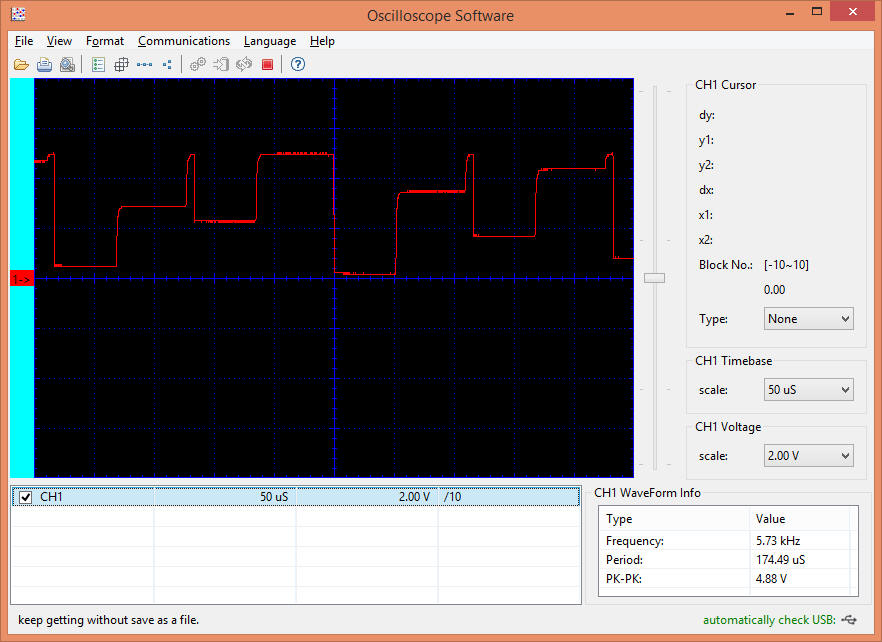
A view of the DCC waveform as it enters the Arduino
|