| Introduction
Please Note:
This page contains my notes on my first design for the
controller and software - the latest design, with updated software,
is here:
Arduino DCC Controller Thanks to a posting by Geoff Bunza on the MRH forum. In that article Geoff describes how one can build a small decoder that can be used to trigger up to 17 discrete events. I have details about my experiments with this project here: http://www.trainelectronics.com/DCC_Arduino/ The next logical step is to create a dedicated DCC controller that can be used to trigger events. I found this listing http://railstars.com/software/cmdrarduino/ and have been testing the Arduino libraries and code with great success. |
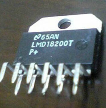
| The Controller If you are willing to change settings (such as DCC address and functions) by revising Arduino code the hardware that is needed to get things working is minimal. Just about any Arduino (I use the tiny mini) will take care of sending DCC information. In addition you need some sort of DCC booster that takes the signals from the Arduino and uses them to put power on the track. I use a simple circuit that is based on the MiniDCC Project. My notes on that booster are here: http://www.trainelectronics.com/DCC_Booster/ In order to use the Arduino controller with that booster simply connect the output from the Arduino to pin 3 on the booster's power chip. Make to pull the ENABLE pin (pin 4) on the LM18200 low as well. |
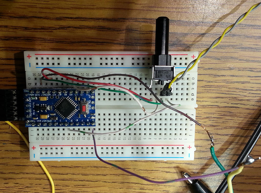
| The Arduino Hardware As you can see the hardware is minimal. A potentiometer connected to pin 4 and the output to the booster coming from pin A0.
The two connections between the Arduino and booster are ground (going to pin 7 on the LMD18200 - the green wire) and the DCC signal (going to pin 3 on the LMD18200 - the yellow wire.) Note that the optocoupler has been removed from its socket.
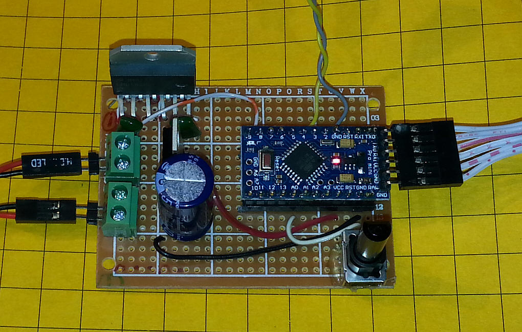
The board below is a complete DCC controller test unit that contains the Arduino and the LMD18200 H-Bridge along with a potentiometer to control speed and a single push button to turn the bell on and off. It is not pretty but it works!
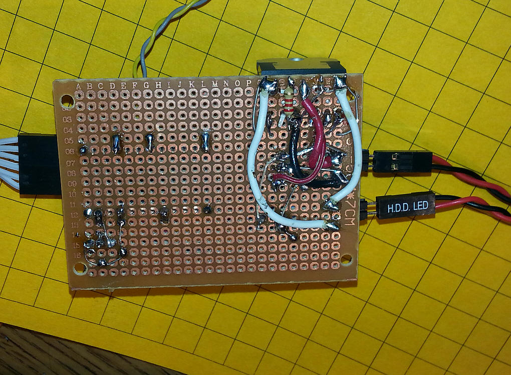
Speaking of "not pretty" the back of the board is very busy under the H-Bridge as many connections are done there including the larger gauge wires that carry the input and output power.
|
| The Software The libraries and sample code are available here: https://github.com/Railstars/CmdrArduino The three library files need to be placed in the "libraries" subdirectory in the Arduino's file location in Program Files or Program Files (x86). I named my subdirectory (under Program Files (x86) CmdrArduino_master |
| Minimal Arduino Program
CmdrArduino_minimum Note: to change the DCC
address (the program below uses address 3) change the two lines that
look like this: In the lines above I changed the 3 to a 9 to change to DCC address 9
|
| Software for Bell Control. too The code below turns the bell on when the button is pressed and turns it off when it is pressed again. /********************
* Creates a minimum DCC command station from a potentiometer connected to analog pin 0,
* and a button connected to ground on one end and digital pin 4 on the other end. See this link
* http://www.arduino.cc/en/Tutorial/AnalogInput
* The DCC waveform is output on Pin 9, and is suitable for connection to an LMD18200-based booster directly,
* or to a single-ended-to-differential driver, to connect with most other kinds of boosters.
********************/
#include <DCCPacket.h>
#include <DCCPacketQueue.h>
#include <DCCPacketScheduler.h>
DCCPacketScheduler dps;
unsigned int analog_value;
char speed_byte, old_speed = 0;
byte count = 0;
byte prev_state = 1;
byte F0 = 0;
void setup() {
Serial.begin(115200);
dps.setup();
//set up button on pin 4
pinMode(4, INPUT);
digitalWrite(4, HIGH); //activate built-in pull-up resistor
}
void loop() {
//handle reading button, controls F0
byte button_state = digitalRead(4); //high == not pushed; low == pushed
if(button_state && (button_state != prev_state))
{
//toggle!
F0 ^= 1;
Serial.println(F0,BIN);
if(F0 == 1) //bell -- ring or stop ringing
{
dps.setFunctions0to4(3,DCC_SHORT_ADDRESS,0x03);
}
else
{
dps.setFunctions0to4(3,DCC_SHORT_ADDRESS,0x00);
}
}
prev_state = button_state;
//handle reading throttle
analog_value = analogRead(0);
analog_value = constrain(analog_value, 0,1016); //wants to run backwards at exterme... strange!
speed_byte = (analog_value >> 2)-127 ; //divide by four to take a 0-1023 range number and make it 1-126 range.
if(speed_byte != old_speed)
{
if(speed_byte == 0) //this would be treated as an e-stop!
{
if(old_speed > 0) speed_byte = 1;
else speed_byte = -1;
}
Serial.print("analog = ");
Serial.println(analog_value, DEC);
//Serial.print("digital = ");
//Serial.println(speed_byte, DEC);
speed_byte = constrain(speed_byte, -127, 127);
Serial.print("digital = ");
Serial.println(speed_byte, DEC);
dps.setSpeed128(3,DCC_SHORT_ADDRESS,speed_byte);
old_speed = speed_byte;
// dps.setFunctions0to4(3, DCC_SHORT_ADDRESS, 0x03); //02 & 03 started bell (I think) 04 horn
// dps.setFunctions0to4(3, DCC_SHORT_ADDRESS, 0x04); //02 & 03 started bell (I think) 04 horn
}
dps.update();
++count;
}
/********************
The functions setFunctions0to4() and setFunction5to9() both expect for the last parameter a bitfield that describes whether each function should be on or off. So, for example
setFunctions0to4(3, DCC_SHORT_ADDRESS, 0x01) would turn F0 on, and F1, F2, F3, F4 off.
setFunctions0to4(3, DCC_SHORT_ADDRESS, 0x02) would turn F1 on, and F0, F2, F3, F4, etc off.
One way to make it easier would be to do something like this:
#define F0 0x01
#define F1 0x02
#define F2 0x04
#define F3 0x08
#define F4 0x10
then to turn functions on and off, you can simply bitwise “or” the functions you want on:
setFunction0to4(3, DCC_SHORT_ADDRESS, F0 | F1) would turn on F0 and F1, and turn off the remainder.
0to4
5to8
9to12
********************/
|
|
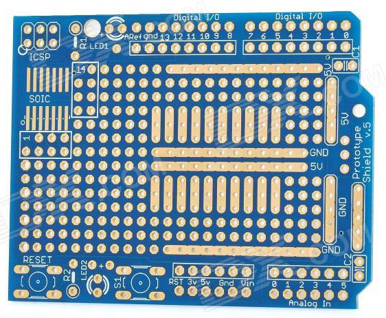
Shield Version of the Controller In keeping with the "shield" theory of building circuits for the Arduino I decided to build up a single board DCC controller circuit. The parts list is below. |
|
Parts Arduino shield board: http://www.dx.com/p/arduino-prototyping-shield-pcb-board-blue-138294#.VBi1gBbEf5A
LMD18200 - http://www.ebay.com/itm/390221396945?_trksid=p2059210.m2749.l2649&ssPageName=STRK%3AMEBIDX%3AIT
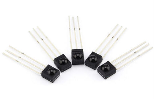
Heat Sink: http://www.suntekstore.com/goods-14004198-12pcs_aluminum_heat_sink_for_to220_l298n.html Two Pin Terminals: http://www.ebay.com/itm/5-x-DG301-Screw-Terminal-Block-2-Positions-5mm-FREE-SHIPPING-/250983097231?pt=LH_DefaultDomain_0&hash=item3a6fc2238f Tantalum cap 4.7uF: http://www.ebay.com/itm/10-x-4-7uF-25V-Radial-Capacitor-Tantalum-Get-It-Fast-/320657882024?pt=LH_DefaultDomain_0&hash=item4aa8b2fba8 IR Receiver module: http://www.ebay.com/itm/AGH-5Pcs-IR-Receiver-Module-38kHz-TSOP4838-DIP-3-SSY-2761-/141191904377?pt=LH_DefaultDomain_0&hash=item20dfb17c79
|
 |
Arduino Code (for starters!) - version
CmdrArduino_Controller_IR_LCD_v2_2_working_2_remotes_9_Functi/*
d. bodnar 9-20-2014
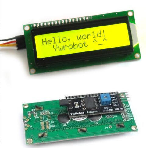
Uses 2 line LCD for display
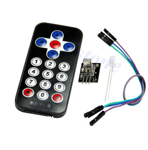
Uses IR remote control for throttle & functions (functions not working well yet)
Uses CmdArduino library for DCC output
UP = faster - 13 - hold to repeat
DN = slower - 17 -hold to repeat
* = STOP - 11
# = Disable / enable DCC (pin 8) -12
< = - 14
> = -16
OK = Menu choices -15
*/
#include<EEPROM.h>
int irButton;
#include <IRremote.h>
int RECV_PIN = 11;
int Enable_PIN = 8; //low to enable DCC, high to stop
IRrecv irrecv(RECV_PIN);
decode_results results;
#include <DCCPacket.h>
#include <DCCPacketQueue.h>
#include <DCCPacketScheduler.h>
DCCPacketScheduler dps;
unsigned int analog_value=0;
char speed_byte, old_speed = 0;
byte Fx = 0;
byte DCCAddress = 3;
int irCode = 0;
int inMenu = 0; // keeps track of being in the menu area 0=out, 1=in
int digits = 0;
int upFlag = 0; // trying to get keys to repeat!
int dnFlag = 0;
#include <Wire.h>
#include <LCD.h>
#include <LiquidCrystal_I2C.h>
#define I2C_ADDR 0x27 // <<----- Add your address here. Find it from I2C Scanner
#define BACKLIGHT_PIN 3
#define En_pin 2
#define Rw_pin 1
#define Rs_pin 0
#define D4_pin 4
#define D5_pin 5
#define D6_pin 6
#define D7_pin 7
byte fn0to4 = 0; // DCC function variables
byte fn5to8 = 0;
byte fn9to12 = 0;
LiquidCrystal_I2C lcd(I2C_ADDR,En_pin,Rw_pin,Rs_pin,D4_pin,D5_pin,D6_pin,D7_pin);
void setup() {
DCCAddress = EEPROM.read(0);
if(DCCAddress >=100){ // set defalut as 3 if not in proper range (0-99)
DCCAddress = 3;
}
pinMode(Enable_PIN, OUTPUT);
lcd.begin (16,2); // LCD is 16 characters x 2 lines
lcd.setBacklightPin(BACKLIGHT_PIN,POSITIVE);
lcd.setBacklight(HIGH); // Switch on the backlight
lcd.home (); // go home
Serial.begin(115200);
lcd.setCursor(0,0);
lcd.print("Version 2.2 ");
lcd.setCursor(0,1);
lcd.print("9-20-2014 ");
delay(1500);
lcd.clear();
irrecv.enableIRIn(); // Start the receiver
dps.setup();
//set up button on pin 4
pinMode(4, INPUT);
digitalWrite(4, HIGH); //activate built-in pull-up resistor
}
void loop() {
digitalWrite(Enable_PIN, LOW);// HIGH = disable DCC
lcd.setCursor(0,0);
lcd.print("Speed=");
lcd.print(speed_byte, DEC);
lcd.print(" ");
lcd.setCursor(11,0);
lcd.print("ad=");
if(DCCAddress <=9){
lcd.print("0"); // add leading zero for single digit addresses
}
lcd.print(DCCAddress, DEC);
lcd.setCursor (0,1); // go to start of 2nd line
lcd.print("IR code ");
lcd.print(irButton, DEC);
lcd.print(" ");
if (irrecv.decode(&results))
{
translateIR();
Serial.println(irButton,DEC);
irrecv.resume(); // Receive the next value
}
byte button_state = digitalRead(4); //high == not pushed; low == pushed
if ((irButton >0 && irButton <13) | (irButton ==14 | irButton == 16)){
upFlag=0;
dnFlag=0; ////MAY NEED TO PUT THIS ON EACH KEY
}
if(irButton >=1 && irButton <10){
// Serial.println( "FOUND 1 to 10!!!!!");
doFunction(irButton);
irButton=0;
}
if (irButton == 10)
{
lcd.setCursor (0,1); // go to start of 2nd line
lcd.print("FN code ");
lcd.print(irButton, DEC);
Serial.println("got a keypad button 0 (reads as 10)");
dps.setFunctions0to4(DCCAddress,DCC_SHORT_ADDRESS, B00000000);
dps.setFunctions5to8(DCCAddress,DCC_SHORT_ADDRESS, B00000000);
irButton = 0;
delay(500);
}
// MENU SECTION - stays here to get DCC address
if (irButton==15 ) //OK key for menu choices
{
Serial.println("found OK (menu)");
inMenu=1;
lcd.clear(); // blank screen
lcd.setCursor(0,0);
lcd.print("MENU");
lcd.setCursor(0,1);
lcd.print("Ent 2 digit add");
for (int i =0; i = 1; i++){ // do twice
if (irrecv.decode(&results))
{
translateIR();
irrecv.resume(); // Receive the next value
}
if (irButton == 15 && inMenu == 0){
Serial.print("BREAK OUT ");
Serial.println(inMenu, DEC);
inMenu=0;
irButton=0;
digits=0;
lcd.clear();
break;
}
if (irButton >=1 && irButton <=10)
{
if (digits==1){
DCCAddress = DCCAddress * 10;
Serial.print("x10 address ");
Serial.println(DCCAddress, DEC);
if(irButton != 10){ // only add it not zero (zero button or remote returns a 10)
DCCAddress = DCCAddress + irButton;
}
lcd.setCursor(0,1);
if(DCCAddress <=9){
lcd.print("0"); // add leading zero for single digit addresses
}
lcd.print(DCCAddress, DEC);
lcd.setCursor(0,0);
lcd.print("OK to Exit Menu:");
digits = 3;
inMenu=0;
EEPROM.write(0,DCCAddress);
}
if (digits ==0){
DCCAddress = irButton;
if (DCCAddress==10){
DCCAddress = 0; // "0" button returns 10 so make it zero
}
Serial.print("dig 1 address ");
Serial.println(DCCAddress, DEC);
lcd.clear(); // blank screen
lcd.setCursor(0,0);
lcd.print("New Address");
lcd.setCursor(0,1);
lcd.print(DCCAddress, DEC);
digits = 1;
delay(500);
irButton=0;
}
Serial.print("new address ");
Serial.println(DCCAddress, DEC);
}
irButton=0;
}
//// irrecv.resume(); // Receive the next value
irButton=0;
}
//END MENU SECTION
if (irButton==13 | (irButton==99 && upFlag==1)) // repeat key (99)
{
Serial.println("found UP");
analog_value++;
upFlag=1;
dnFlag=0;
irButton=0;
}
if (irButton==16)
{
Serial.println("found UP ");
analog_value++;
irButton=0;
}
if (irButton ==17 | (irButton==99 && dnFlag==1))
{
Serial.println("found DN");
analog_value--;
dnFlag=1;
upFlag = 0;
irButton=0;
}
if (irButton ==14)
{
Serial.println("found DN ");
analog_value--;
irButton=0;
}
if (irButton==11) //* key - does STOP
{
Serial.println("found ***");
analog_value=0;
irButton=0;
}
speed_byte =analog_value;// (analog_value >> 2)-127 ; //divide by four to take a 0-1023 range number and make it 1-126 range.
if(speed_byte != old_speed)
{
if(speed_byte == 0) //this would be treated as an e-stop!
{
if(old_speed > 0) speed_byte = 1;
else speed_byte = -1;
}
speed_byte = constrain(speed_byte, -127, 127);
dps.setSpeed128(DCCAddress,DCC_SHORT_ADDRESS,speed_byte);
old_speed = speed_byte;
}
dps.update();
}
int translateIR() // takes action based on IR code received
// describing KEYES Remote IR codes (first) and Sony IR codes (second)
{
Serial.println(results.value, HEX);
switch(results.value)
{
case 0xFF629D:
Serial.println(" UP");
irButton = 13;
break;
case 0x90:
Serial.println(" UP");
irButton = 13;
break;
case 0xFF22DD:
Serial.println(" LEFT");
irButton = 14;
break;
case 0xC90:
Serial.println(" LEFT");
irButton = 14;
break;
case 0xFF02FD:
Serial.println(" -OK-");
irButton = 15;
break;
case 0x70:
Serial.println(" -MENU-");
irButton = 15;
break;
case 0xFFC23D:
Serial.println(" RIGHT");
irButton = 16;
break;
case 0x490:
Serial.println(" RIGHT");
irButton = 16;
break;
case 0xFFA857:
Serial.println(" DOWN");
irButton = 17;
break;
case 0x890:
Serial.println(" DOWN");
irButton = 17;
break;
case 0xFF6897:
Serial.println(" 1");
irButton = 1;
break;
case 0x10:
Serial.println(" 1");
irButton = 1;
break;
case 0xFF9867:
Serial.println(" 2");
irButton = 2;
break;
case 0x810:
Serial.println(" 2");
irButton = 2;
break;
case 0xFFB04F:
Serial.println(" 3");
irButton = 3;
break;
case 0x410:
Serial.println(" 3");
irButton = 3;
break;
case 0xFF30CF:
Serial.println(" 4");
irButton = 4;
break;
case 0xC10:
Serial.println(" 4");
irButton = 4;
break;
case 0xFF18E7:
Serial.println(" 5");
irButton = 5;
break;
case 0x210:
Serial.println(" 5");
irButton = 5;
break;
case 0xFF7A85:
Serial.println(" 6");
irButton = 6;
break;
case 0xA10:
Serial.println(" 6");
irButton = 6;
break;
case 0xFF10EF:
Serial.println(" 7");
irButton = 7;
break;
case 0x610:
Serial.println(" 7");
irButton = 7;
break;
case 0xFF38C7:
Serial.println(" 8");
irButton = 8;
break;
case 0xE10:
Serial.println(" 8");
irButton = 8;
break;
case 0xFF5AA5:
Serial.println(" 9");
irButton = 9;
break;
case 0x110:
Serial.println(" 9");
irButton = 9;
break;
case 0xFF42BD:
Serial.println(" *");
irButton = 11;
break;
case 0xC70: //EXIT
Serial.println(" *");
irButton = 11;
break;
case 0xFF4AB5:
Serial.println(" 0");
irButton = 10;
break;
case 0x910:
Serial.println(" 0");
irButton = 10;
break;
case 0xFF52AD:
Serial.println(" #");
irButton = 12;
break;
case 0xA90: //POWER
Serial.println(" #");
irButton = 12;
break;
case 0xFFFFFFFF:
Serial.println(" REPEAT");
irButton = 99;
break;
default:
Serial.println(" other button ");
irButton = 99;
}// End Case
delay(100); // Do not get immediate repeat
} //END translateIR
//START DO FUNCTION BUTTONS
int doFunction(int irButton){
// Serial.println("Got to Function");
// Serial.println(irButton, DEC);
int irTemp= irButton-1;
lcd.setCursor (0,1); // go to start of 2nd line
lcd.print("FN code ");
lcd.print(irButton, DEC);
Serial.print("got a keypad button ");
Serial.println(irButton,DEC);
if (irTemp<=4){
if(bitRead(fn0to4,irTemp)== 0 ){
bitWrite(fn0to4,irTemp,1);
}
else {
if(bitRead(fn0to4,irTemp)== 1 ){
bitWrite(fn0to4,irTemp,0);
}
}
dps.setFunctions0to4(DCCAddress,DCC_SHORT_ADDRESS,fn0to4);
Serial.print(fn0to4,BIN);
Serial.println(" fn0to4");
}
if (irTemp>=5){
irTemp=irTemp-5;
if(bitRead(fn5to8,irTemp)== 0 ){
bitWrite(fn5to8,irTemp,1);
}
else {
if(bitRead(fn5to8,irTemp)== 1 ){
bitWrite(fn5to8,irTemp,0);
}
}
dps.setFunctions5to8(DCCAddress,DCC_SHORT_ADDRESS,fn5to8);
Serial.print(fn5to8,BIN);
Serial.println(" fn5to8");
}
irButton = 0;
delay(500);
}
//END DO FUNCTION BUTTONS
|