| About a year ago I started experimenting
with fidget spinners and how you could turn one into a brushless motor. My notes can be seen
by following this link: Fidget Spinner Motors While the project and related videos were very well received there were a number of requests for more. With this in mind I revisited my work and present some additional findings here. |
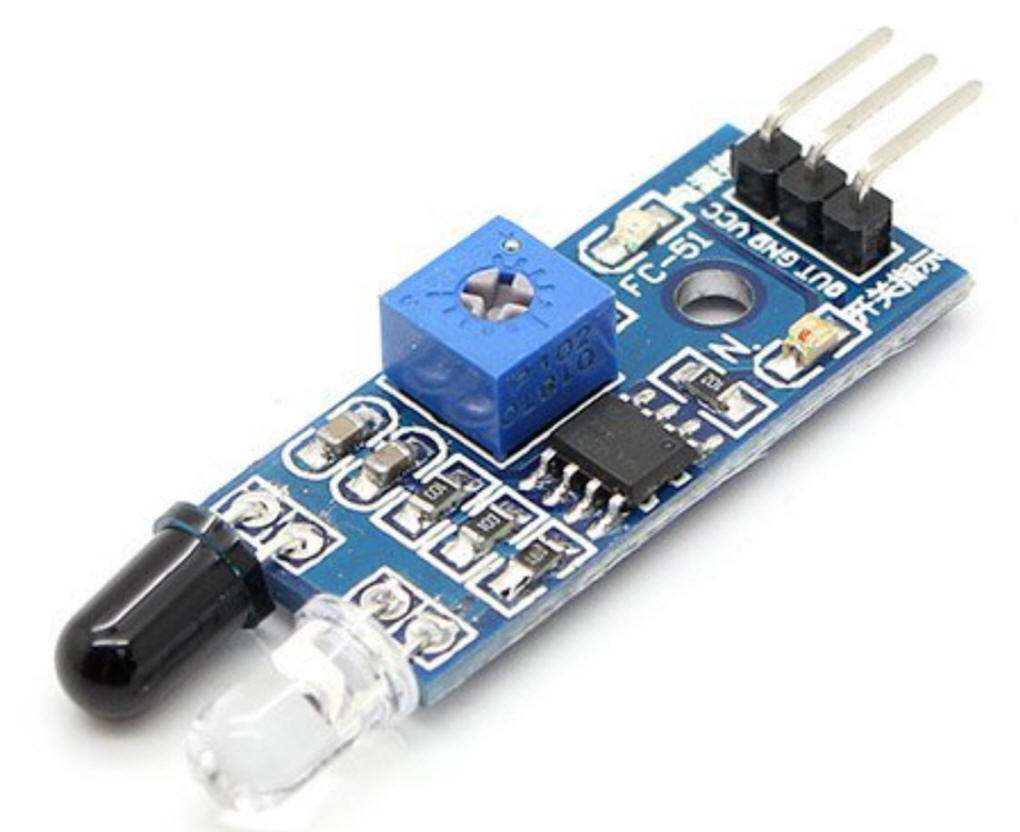
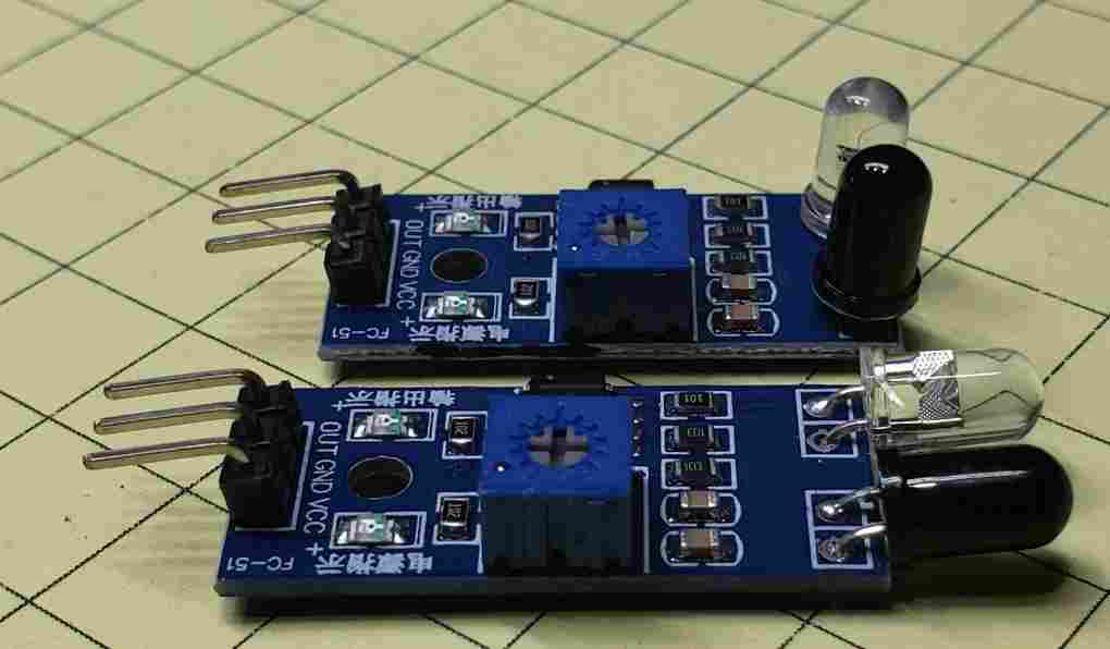
| New IR Sensor A brushless motor needs some sort of sensor to trigger the magnetic coil that keeps the motor spinning. These can include mechanical switches, magnetic reed switches, Hall Effect magnetic sensors and various light sensors. For this series of experiments I decided to try a simple IR (infrared) sensor that includes an infrared emitter and an infrared detector on the same small board - they are available from Amazon and eBay. Prices can be as low as $1.00 each. They only have 3 connections, +5 volts, ground and output. When the sensor is close to an object that reflects IR the output goes high. The small blue potentiometer is used to adjust the sensitivity and an on-board LED lights when the output is active.
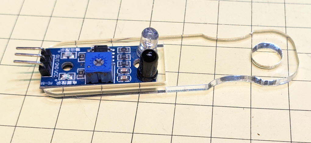
As delivered the sensor looks like the one shown here. I did a slight modification to better fit my fidget spinner setup. I gently bent the emitter and detector 90 degrees so that they both pointed up rather than straight ahead. That allowed me to place the sensor under the spinner rather than above it.
|
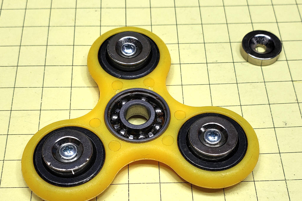
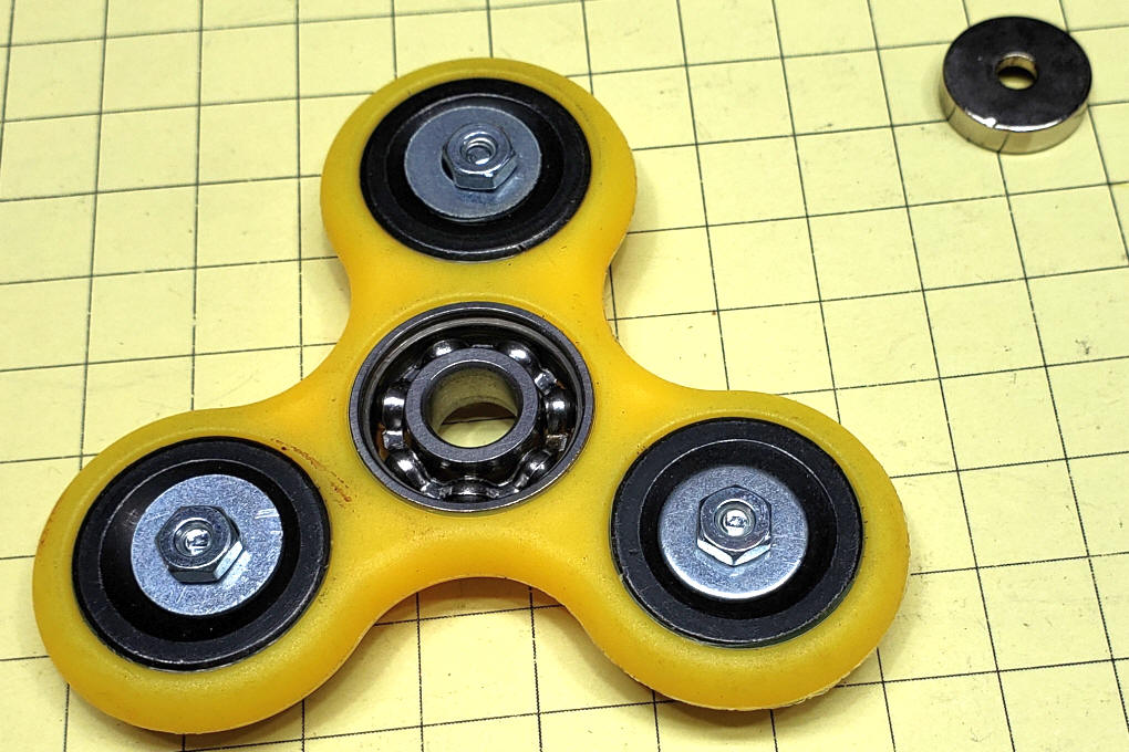
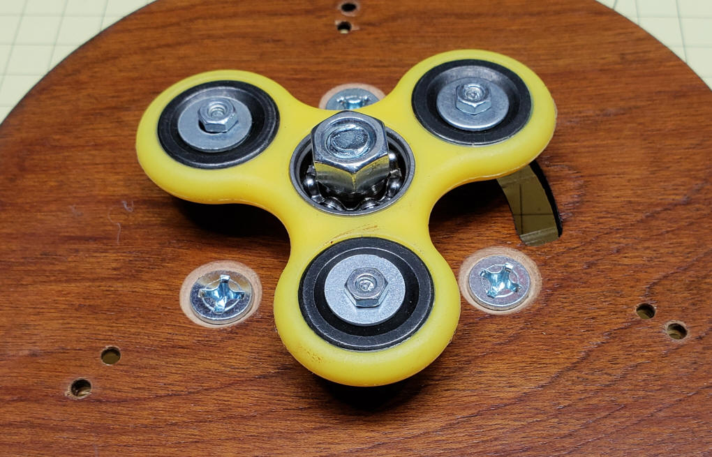
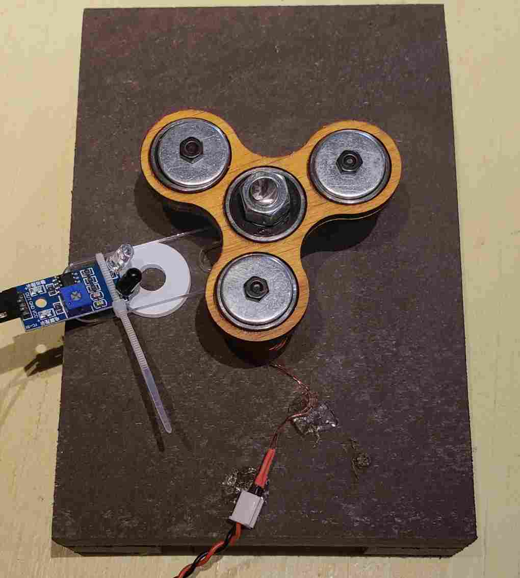
| Magnet Safety Magnets can be attached to the three lobes of the fidget spinner in a number of ways. I initially used hot melt glue but found that the magnets could become loose and fly off at high speed as the spinner rotated. For this project I opted to mechanically fasten the magnets. I found round magnets with tapered holes in the center at Banggood. They are idea for this application since they can be bolted to the lobes as shown in these photos. They are also available from eBay & Amazon. Just search for round magnet countersunk. One word of caution. As with most rare earth magnets they are quite brittle and will shatter if they are allowed to slam into one-another from a distance of an inch or two. They can also be cracked if the bolts that attach them to the fidget spinner are tightened too much. I attached them a bit more than finger tight then used glue to lock the nut to the bolt to keep them from loosening.
|
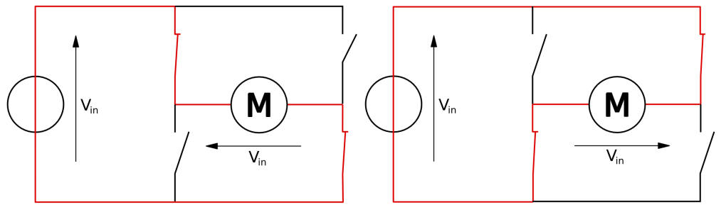
| H-Bridge In many of my first set of experiments I used a transistor (actually a MOSFET) to turn the coil on or off. This setup worked well but the electromagnet only "pulled" the magnets on the lobes of the fidget spinner for a short time as the lobe passed the sensor. To make the coil do double duty, both pulling and pushing the magnets, I needed a more sophisticated device that would do more than just turn the power on or off. I needed a component that would reverse the flow of current that goes through the coil so that for part of the time it had its north pole at the top and for the rest of the time its south pole was at the top, The component that I used to do this is called an "H-Bridge". It is the solid state equivalent of a speed control ccombined with a double pole double throw switch. They are made up of four transistors wired in such a way that when two of them are on the current flows to give one polarity on the output wires and when the other two transistors are on the polarity is the opposite. They are commonly used to control motors on robotic platforms and other devices. When the polarity is set one way the motor goes forward and when the polarity reverses that motor turns the other way. This image from Wikipedia shows a simple representation of what an "H-Bridge" does.
The power goes into the circuit at Vin and the motor (or electromagnet) is at "M". The four switches that make up the "H-Bridge" surround the motor. When the upper left switch and the lower right switch are closed the motor goes in one direction, as shown in the first image. When those switches are opened and the other two are closed the motor goes the other way. I used two different devices for this project. Both are available from eBay and Amazon. The first is a low current device that is limited to 15 volts (eBay Amazon ) and the other can handle much more current and up to 16 volts (eBay Amazon ) In order to use an H-Bridge you need to use an Arduino or other microcontroller that will control its various input pins to turn the current one way or the other as the fidget spinner turns.
|
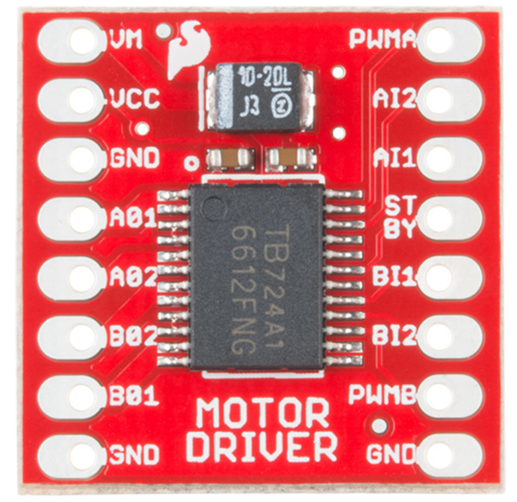
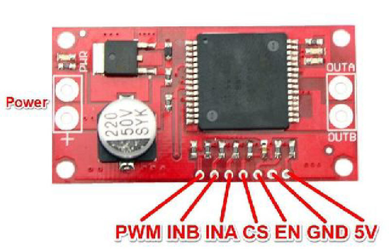
| Schematic The wiring diagrams for the two H-Bridges are slightly different. The smaller board supports 1 or 2 motors and its pin labels are shown here
Since only one motor circuit is needed a number of the pins are not connected. You can wire the two halves of the motor driver together in parallel to increase the current handling capability of the device. Be sure to limit "Coil Power in" to no more than 15 volts.
The VNH2SP30 can supply 20 or more amps, way more current than we will need, at up to 16 volts.
To simplify connections to the Arduino CS and EN and wired directly to +5 volts.
|
|
| Arduino Code The program for the Arduino is quite simple. It looks for a change in the output of the sensor and uses that to reverse the polarity of the H-Bridge. /*REVISITED d. bodnar 9-27-2018
*/
unsigned long time;
unsigned long time2;
int flag = 0;
int flag2 = 0;
int SpinSensor = 8; // IR sensor
int SpinSensorValue = 0;
#define CW 1
#define CCW 2
int inApin = 2;
int inBpin = 3;
int pwmpin = 5; // PWM's input
int i = 0;;
int duration = 0;
int duration2 = 0;
int xx = 0;
void setup() {
pinMode(SpinSensor, INPUT);
pinMode(inApin, OUTPUT);
pinMode(inBpin, OUTPUT);
pinMode(pwmpin, OUTPUT);
digitalWrite(inApin, LOW);
digitalWrite(inBpin, LOW);
Serial.begin(115200);
Serial.println("<Arduino is ready - version singleMonster-red-test-2.0");
}
void loop() { // working well - scope shows 70Hz @ 6.6.volts x 250ma
SpinSensorValue = digitalRead(SpinSensor); // 1=no IR, 0=sees IR (under arm)
if (SpinSensorValue == 0) {
motorGo(CW, 175);
if (flag2 == 1) {
duration2 = millis() - time2;
flag2 = 0;
}
if (flag == 0) {
time = millis();
flag = 1;
}
}
SpinSensorValue = digitalRead(SpinSensor); // 1=no IR, 0=seesUR (under arm)
if (SpinSensorValue == 1) {
motorGo(CCW, 175);
if (flag2 == 0) {
time2 = millis();
flag2 = 1;
}
if (flag == 1) {
duration = millis() - time;
xx++;
if (xx >= 10) {
xx = 0;
}
flag = 0;
}
}
}
//cw=1, ccw=2
void motorGo( uint8_t direct, uint8_t pwm) //Function that controls the variables: motor(0 ou 1), direction (cw ou ccw) e pwm (entra 0 e 255);
{
if (direct == 1) { //CW
digitalWrite(inApin, HIGH);
digitalWrite(inBpin, LOW);
}
else { //CCW
digitalWrite(inApin, LOW);
digitalWrite(inBpin, HIGH);
}
analogWrite(pwmpin, pwm);
}
|
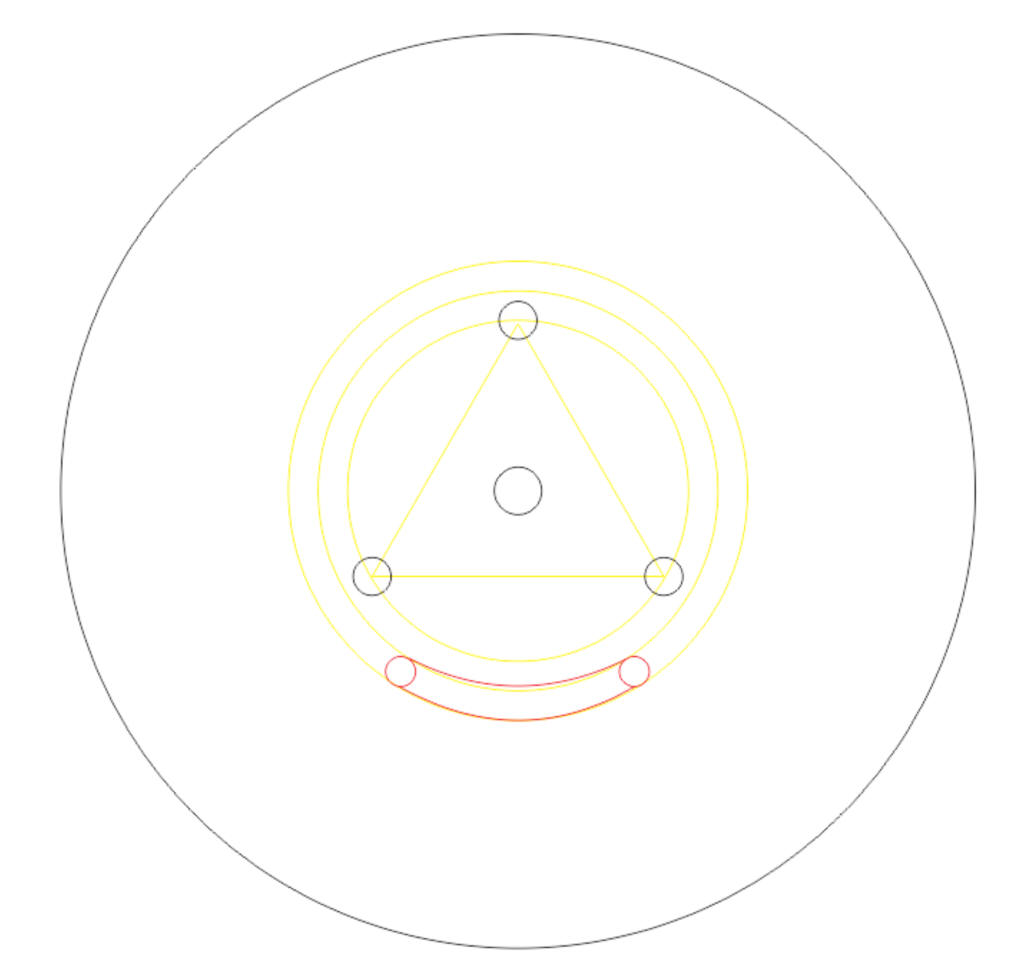
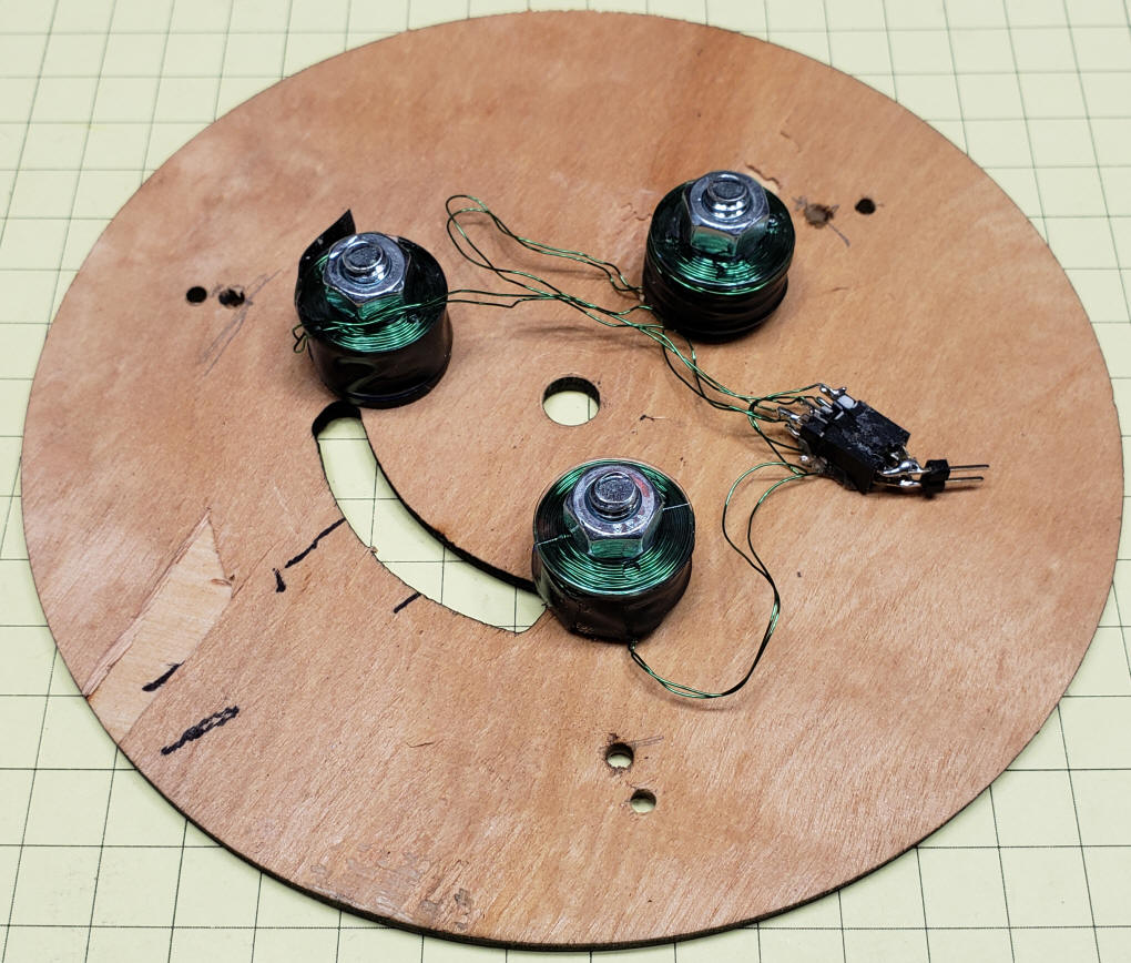
| Three Coils, Not Just One Up to this time I have build brushless motors using three magnets on the fidget spinner and a single electromagnet coil on the base. While this setup worked it makes sense that using three coils would have the potential to supply more power and smoother operation. The three coil base has a 5/16" hole in the center, three 1/4" holes for the electromagnets and a slot for the IR sensor. The yellow lines were just used for setup and can be ignored.
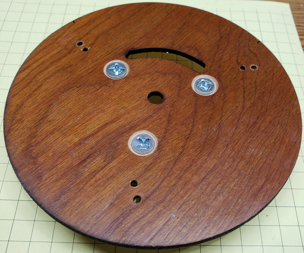
I wound three identical coils and wired them in parallel so that all three would show the same magnetic pole when the power was on with a given polarity. The three bolts that hold the coils are shown here. The have tapered heads that fit into countersunk holes so that they are flush with the top of the board. The slot at the top is for the IR sensor so that it can look "up" at the bottom of the fidget spinner.
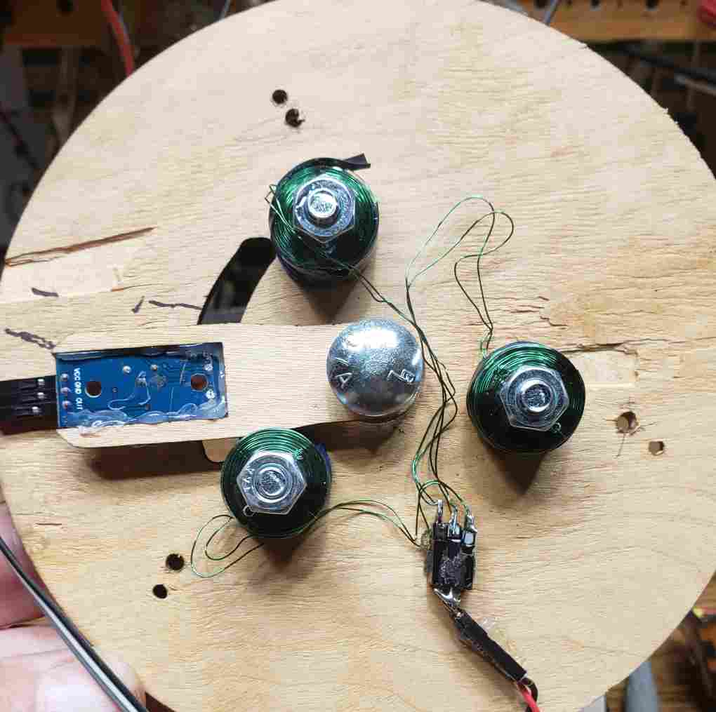
The back view shows the coils. They are wired in parallel and terminate in one 2 pin connector.
The spinner has been bolted to the main board. Be sure that the nut and any washers that you might use do not bind the bearing. It must spin freely.
|
| Measure Speed of Rotation In order to measure the speed of rotation I used both a frequency counter and an oscilloscope. I connected to the circuit's ground and to the output of the IR sensor to these devices. The measured frequency was three times the number of rotations per second since the sensor was detecting three lobes going by for each rotation. To convert this to revolutions per minute (RPM) I just divided the frequency by three then multiplied that result by 60. Or you can just multiply the frequency by 20 since dividing a number by three then multiplying by 60 is the same as multiplying by 20.
|
| Tachometer All of the rotational speed measurements taken by observing the IR sensor were the same and appeared to be correct. To confirm this using an independent measuring device I decided to build a stand-alone tachometer. This device uses a small laser and a photo transistor to count the number of times a lobe breaks the laser beam in a given time period. The hardware is composed of an Arduino Pro Mini (Amazon eBay), a phototransistor, I prefer the ones in a metal can, ( Amazon eBay), a laser diode (Amazon eBay) and a 10K resistor. In addition I added a 2 line LCD display with I2C interface to show the results (Amazon eBay). The schematic is here:
|
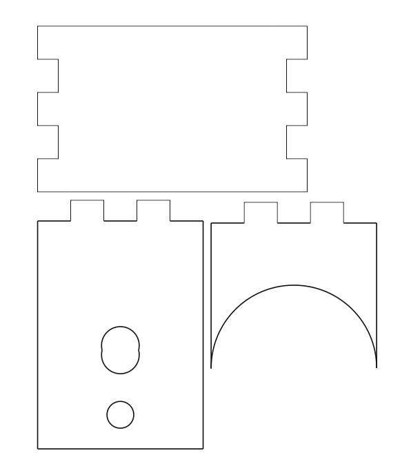
| Tachometer Sensor I wanted a sensor that I could move around the motor so I built up a base that used a small mirror to reflect the laser beam from the small laser to the phototransistor, both of which were mounted a the top of the unit. <PHOTO OF SENSOR> These three pieces were cut from 1/8" plywood. The laser goes into the oblong hole and the phototransistor into the round hole. When gluing them together make sure that the top and bottom are parallel. Attach the small mirror to the bottom piece. Glue in the phototransistor first then the laser, adjusting its position so that the laser beam reflects into the enter of the phototransistor. I found that masking off most of the phototransistor. I used a thin piece of brass sheet (paper thin) with a small hole poked into it to cover most of the phototransistor. Once that was done the sensor reacted very nicely.
<PHOTO OF SENSOR ON SPINNER UNIT>
|
| Metal Fidget Spinner /w Better Bearings Up to this point I had been working with inexpensive plastic fidget spinners. I wondered if buying a higher quality spinner would make a difference. The short answer is "YES!" disassembly custom washers mounting |
| Speed 1 5/8" radius = 3.25" diameter @ 5000 rpm the outer rim of the spinner goes 5000 x circumference = 5000 x pi x 3.25 = 5000 x 10.205 = 51,025 inches / minute = 4252 feet / minute = 255125 feet / hour = 48.32 mph |