Crest Electronics HO Train Engineer Revolution
revised 11-30-14
Introduction
In 2007 I began working with Aristo Craft to help with the design of a new
large scale radio control system. This came to be called the Train
Engineer Revolution and has been adopted by large scale hobbyists
throughout the world. The system was designed to take advantage of 2.4 GHz
frequencies for interference rejection, range and reliability.
With the original Revolution well entrenched in the G-scale community Crest Electronics (the company now handling Aristo Craft's electronics items) has set its sites on expanding radio control to the HO world.
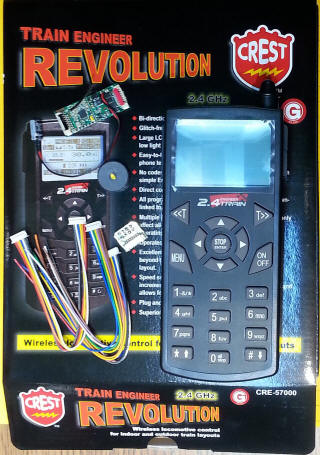
The main components of the system are shown here. The transmitter, which will control up to 99 locomotives, is on the left and the receiver, which is installed in each locomotive, is on the right. The receiver controls the direction and speed of the locomotive, its forward and rear lights and sound.
Pricings is not firm at this time but a starter set is expected to be about $200 for the transmitter and one receiver. A second, free, receiver may be included for early adopters.
|
|
|
The Receiver
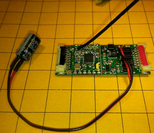
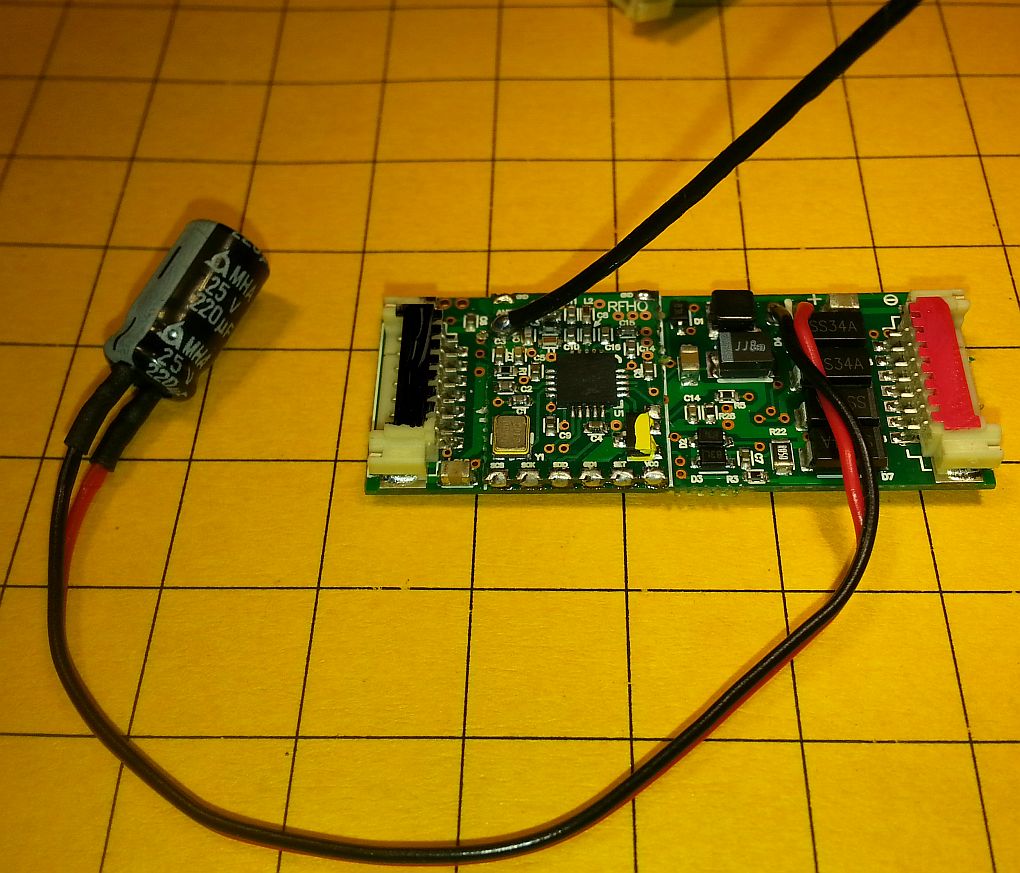
The receiver is shown here. There are plugs at either end of the
board, one marked red and one marked black. The red end goes to the power
/ motor / lights and the black end to the accessory control wires and the
speaker. The red/black wires coming from the right side of the board
connect to a small capacitor that helps to keep the system working when in
encounters dirty track. The black wire at left end of the board is the
radio antenna. If you are operating the locomotive from battery power the
capacitor can be removed.
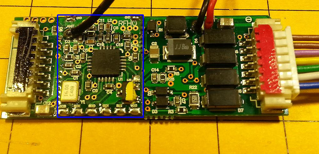
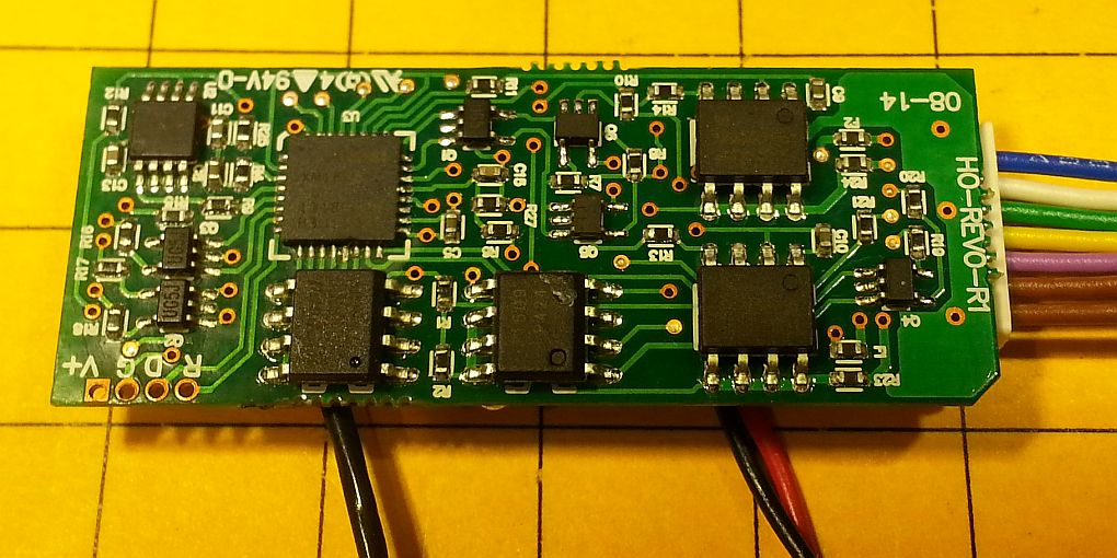
This close-up of the receiver shows its components. There are four diodes on the far right that convert incoming track power (DC or DCC) to DC of fixed polarity. The smaller board at the left (highlighted in blue) is the radio receiver.
The back of the board shows the power control ICs, the sound circuitry and the microcontroller. The transistors that operate the auxiliary outputs and the front and rear LEDs are marked UG5J and can each control up to 100ma. 22 ohm resistors are in series with each transistor output which will limit the current going to the lights and accessories and protect the transistors from damage.
Installation
Installing the receiver is virtually identical to installing a DCC decoder.
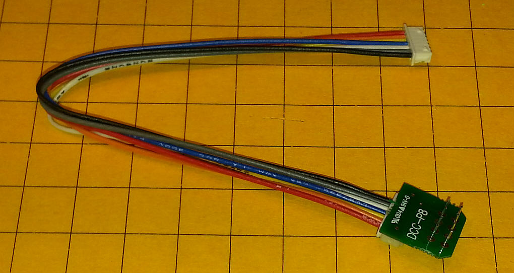
Two connection options are supported. If your locomotive has a standard
NMRA DCC plug a matching cable is supplied with the receiver. One end
plugs into the DCC socket in the locomotive and the other plugs into the
Revolution receiver on the end marked with a red stripe.
If your locomotive is not set up for plug-and-play installation with the DCC socket, wires from the locomotive's wheel pickups and motor must be located and isolated. Again, this is the same procedure used with a non-plug-and-play DCC installation. You must be absolutely sure that the motor and wheel pickup wires are not interconnected before adding the controller or it may be damaged.
This photo shows a Bachmann HO engine with a standard DCC decoder installed. The four connections circled in yellow are the power pickups from the two trucks. The motor connections are circled in blue.
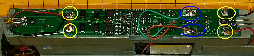
To install the Revolution receiver just remove these connections and the DCC board and wire the power pickup wires to the red/black wires on the Revolution receiver and the grey and orange to the motor. Insulate the connections with heat shrink tubing.
Sound
The receiver has a built-in sound unit that produces sounds for either a
diesel or steam locomotive. It is a polyphonic sound card that can process
more than one sound (the bell and whistle, for example) at the same time.
A speaker was not included in my starter set so I used a small speaker that I had on hand and connected it to the two brown wires that are on the auxiliary wiring harness.
Since space is at a premium inside of HO locomotives, especially diesel ones, a speaker designed for such use may be the best choice.
Battery Power
Although the HO Revolution receiver can be powered from track power it is
ideally suited for battery operation. While it may be possible to mount
batteries in the tender of a steam locomotive, putting them in a trailing car
may be a better choice. Such an installation makes it easy to add charging
plugs and to swap batteries when one is exhausted. It is also a good place
for a larger speaker than the ones that might fit inside of a locomotive.
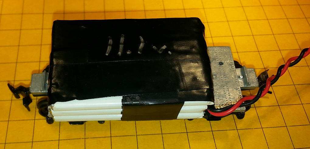
There are a number of choices when it comes to battery chemistry, including nickel cadmium, nickel-metal hydride and lithium ion. Whatever choice you make the battery should supply at least 10 volts for prototypical speeds. For NiCad and NiMH batteries that means using 7 or more cells. Li Ion cells are 3.7 volts each so you can use only 3 cells to provide 11.1 volts. This photo shows 3 cell phone batteries wired in series and mounted to an HO freight car frame. The wires extending to the right connected to the Revolution receiver in my test locomotive.
Small cells can be fit into box cars or gondolas. Unfortunately, the smaller the cell the smaller its capacity. Lithium ion batteries provide the most power for a given size or weight. The batteries that I used are rated at about 700 mAh and can run a locomotive for several hours depending on its size, grades it traverses and how many cars it pulls.
Another option is to use a single Li Ion cell and "stepping up" its voltage with an inexpensive "buck converter". These small electronic circuits take a low input voltage and convert it to an adjustable output that we can use to give proper speed to our locomotives.
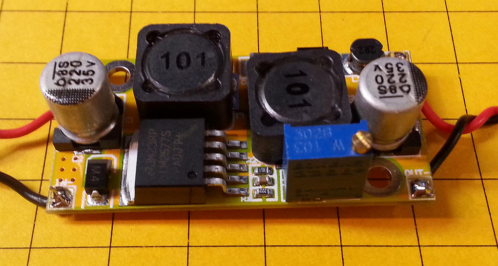
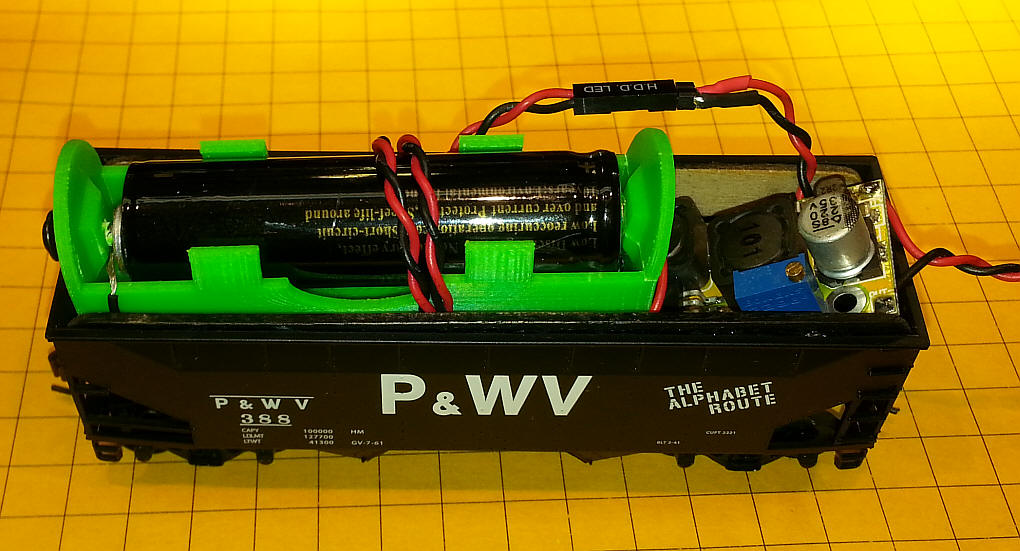
I have done some testing with one of these converters attached to a single 18650 size lithium ion battery. These cells are about twice as large as a AA cell and will fit into a box car or gondola along with the buck converter.
If you decide to give this a try make sure you use a "protected" battery. Since lithium ion batteries can be destroyed if over charged or over discharged an internal circuit is needed to protect from either of these events. The cells that I used are similar to the ones found here:
The current rating for this item is 4000 mAh but it is more like 3000. Even then, it should provide an hour or more of operation. The protection circuit also allows charging from a simple 5 volt cell phone charger. The installation in an HO freight car was for testing.
Crest Electronics is expected to supply a similar battery option in early 2015. It may use Lithium Polymer batteries which can have even more capacity than the ones I used for testing.
The Transmitter
Three AA cells power the transmitter. Press the ON/OFF button to turn
the transmitter on.
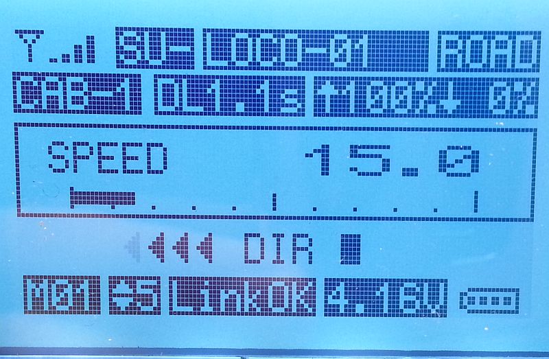
The main screen gives a great deal of information. The symbol in the upper left shows the status of the radio connection to the receiver. SU indicates a single unit (not an MU) and LOCO-01 is the locomotive's name. CAB-1 shows that this is the first locomotive, out of a possible 50. DL is the delay before reversing. SPEED is shown as 15 (out of 100) and DIR shows the locomotive is going backwards. The bottom line shows the speed steps (5) and that the link to the receiver is OK and that the transmitter's batteries are providing 4.16 volts. This is also shown graphically.
|
To set up a new receiver press the MENU button to move to the main menu.
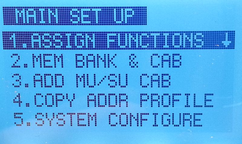
Press ENTER to select ASSIGN FUNCTIONS
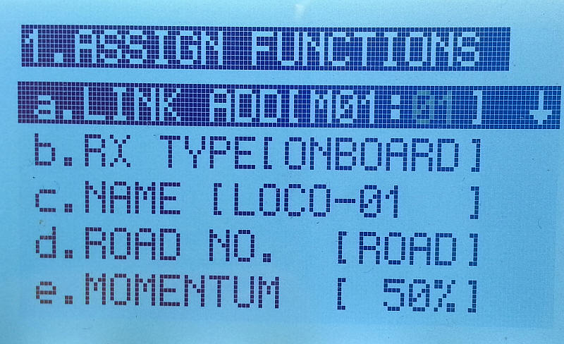
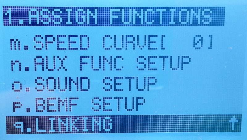
Note the name of the locomotive. Press the down arrow to move to the very bottom of the list where you will find "q.LINKING". None of the options need to be changed for this test.
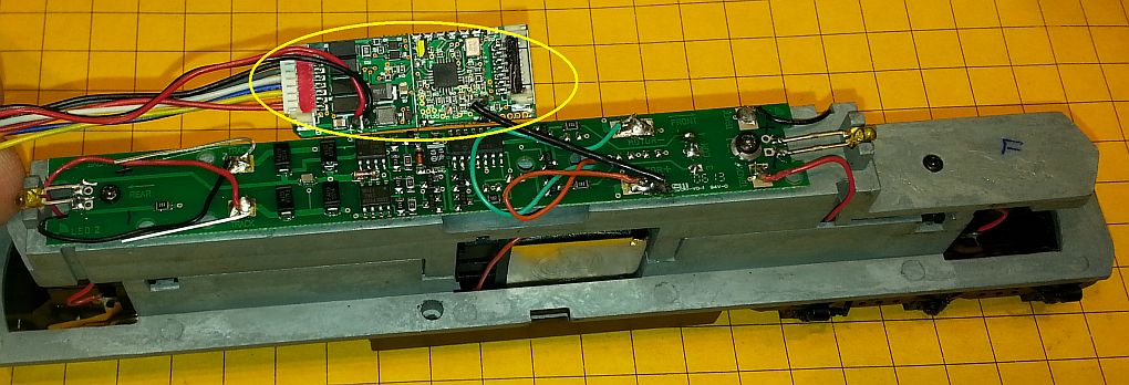
Before pressing STOP/Enter to start the linking process apply power to the locomotive with the receiver installed then place the round magnet, yellow dot down, over the component on the receiver that is also marked in yellow.
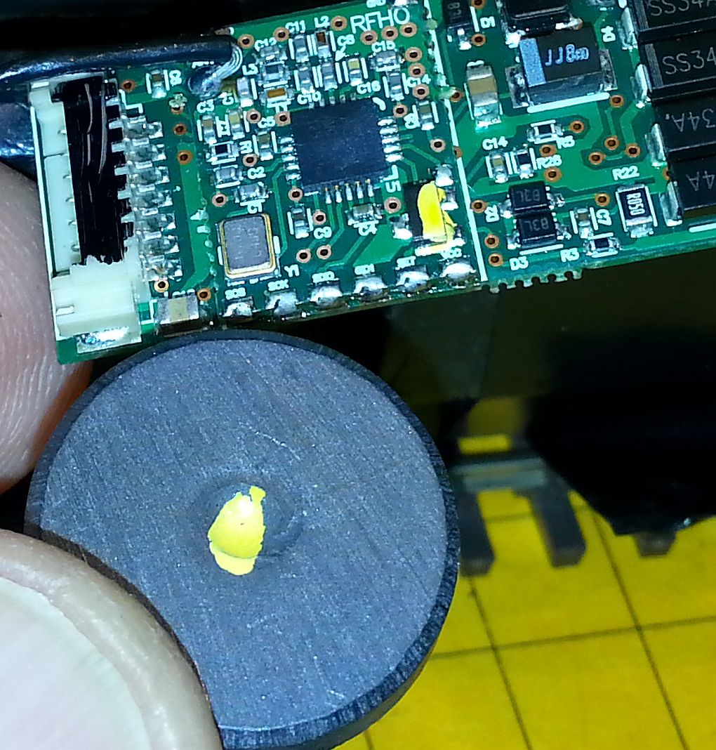
When this is done the headlight LED will start flashing. This indicates that the receiver is "listening" for a link signal. Press ENTER on the transmitter to select LINK and, after a few moments, you should see LINKING SUCCESSFUL displayed
One more step needs to be completed before operating the engine. It must be assigned to a CAB. Press MENU again to return to the main menu. Scroll down with the down arrow to 3. ADD MU/SU CAB and press ENTER.
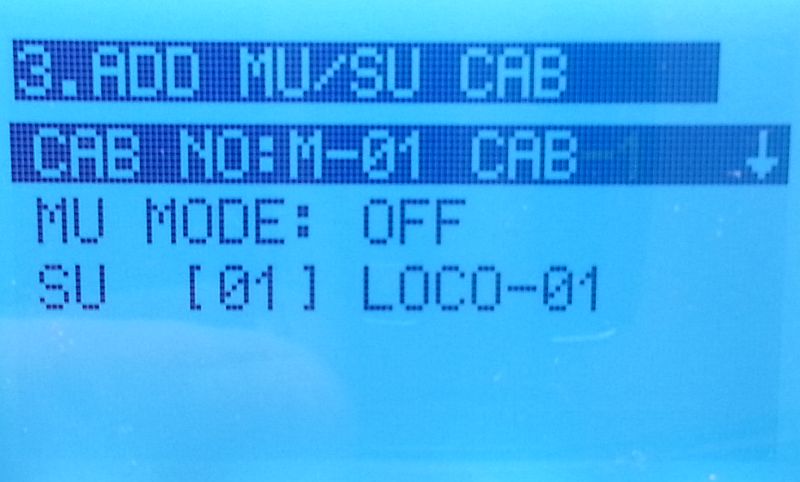
Leave the options as shown making sure that the CAB is associated with LOCO-01, the receiver that we just linked to.
Press the MENU button a few times to return to the main screen.
Press the up and down arrows to change speed and the right and left arrows to change direction.
Details on the operation of the Revolution system can be found on Crest's web page here:
http://www.crest-electronics.net/support.html
and
http://www.crest-electronics.net/learn.html
I also have an introduction to the large scale version on my web page here:
http://www.trainelectronics.com/ART5700TrainEngineerRevolution/article.htm
The operation of the HO and large scale units are nearly identical.
Sound Operation
If you have attached a speaker to the receiver you can experiment with the
sound options.
Button 1 - turns the sound on or off - latching
Button 2 - operates the bell sound - momentary
Button 3 - operates the whistle - momentary
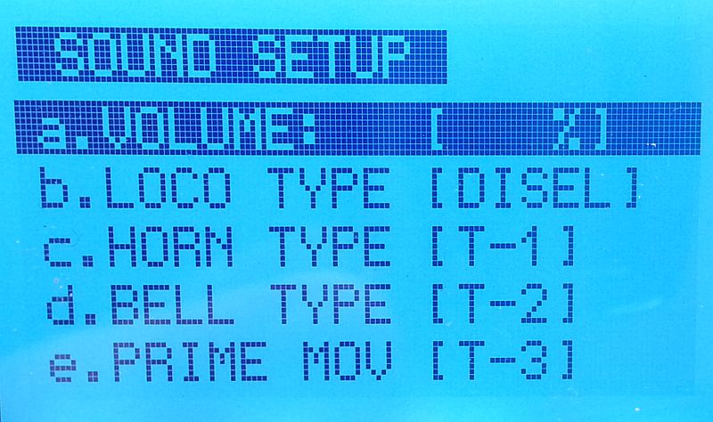
Sound volume can be found under SOUND SETUP in the ASSIGN FUNCTIONS menu. Here you can set the volume, type of sound (diesel or steam) and the types of bell, horn and prime mover. The pre-release unit that I evaluated did not have the alternate sounds installed but the volume control was active. I set it to 100%.
Conclusion
Using radio control to run our model railroads brings a whole new dimension
to operating. A battery powered train doesn't need to worry about dirty
track or what kind of power is available. It will run anywhere! The
Crest HO Revolution is not only innovative but it is also an ideal way for model
railroaders to give radio control operation a try.