Infrared Train Detector
Revised - 06-05-07
Please note - this article is a draft and is missing some photos & some sections are incomplete.
Introduction
Reliably detecting a model train operating on an outdoor layout is problematic at best. Over the last few years I have experimented with and written about a number of different ways to detect them. I have finalized a new design for track-side sensors that works very well and would like to share my findings and this new detection system with you.
This new design is part of a crossing control system that I recently designed for an outdoor garden railway. The new detection units that I came up with for this system are extremely weather resistant and come in two configurations, one for across-the-track detection and one for reflective detection.
Although the new sensors were originally designed as part of the system mentioned above I have put together a stand-alone circuit board that will connect to one or two of the sensors. It is highly configurable and can be set to trigger a relay or throw a turnout based on a variety of conditions. I think you may find it is just what you have been looking for to automate events on your railroad.
Pulsed Infrared Sensors
In the final installment of a series of articles on Garden Railway Sensors (<REFERENCE>)
I discussed the problems that we frequently run into with reliably detecting trains in an outdoor
environment. A number of options were discussed and the hands down winner
was a detector that works by sending out and detecting an invisible beam of
infrared light. When an infrared detector finds that the beam has either
been broken, in the case of an across-the-track sensor, or reflected back, with
the reflective design, it triggers an
event. This can be anything from activating a crossing signal to
throwing a switch.
In order to utilize infrared light in an outdoor environment specialized infrared emitters and detectors must be used. They only generate and react to IR that is pulsed on and off at a rate, 38,000 times each second, that is normally not found in nature. Infrared light is very common in any sunny area but the sun's IR and IR from most other sources is not pulsed on and off rapidly. Using pulsed IR helps to eliminate false triggering of the infrared detector unit. You may recall that this same type of pulsed IR is used by almost every TV remote control that has been build for the last 30 years.
Across-the-Track vs. Reflective Sensors
There are two different ways that IR detectors can be set up. The first operates by sending a beam of infrared light across the track to a detector on the other side. When a train or other object breaks the beam the controller reacts to that event.
<DIAGRAM of across-the-track sensors>
The other configuration places both the IR emitter and the IR detector on the same side of the track. The IR beam is projected across the track towards an open area. The IR emitter and detector are shielded from one another so that no IR can go directly from the emitter to the detector. The detector "sees" IR only when an object, like a train, passes close by and reflects IR back to the detector.
<DIAGRAM of reflective sensor>
Circuit Design
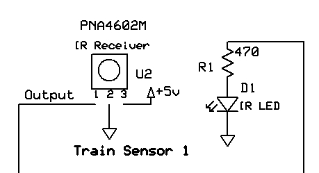
The circuit for the IR emitter and detector utilizes a PIC microcontroller and very few other parts. An LED that emits infrared light is connected to one of the output pins on the microcontroller through a current limiting resistor. The microcontroller pulses that pin on and off 38,000 times each second, generating the 38 KHz pulses that we need. The infrared detector only reacts to pulsed 38 KHz infrared. The circuit uses a three pin device, the PNA4602M, that changes the state of its output pin from +5 volts to 0 volts depending on whether it detects infrared light or not. All of the sophisticated circuitry that is needed to do this reliably is inside of the PNA4602M.
In the schematic below a detector / emitter pair are shown. A number of common symbols are used in this drawing. The small downward facing triangles represent connections to the circuit's ground. Ground is the negative terminal of the power supply or battery. Pin 2 of the PNA4602M and the cathode of the LED connect to ground. The upward facing triangle, on pin 3 of the detector, goes to a source of 5 volts. The output terminal of the detector, pin 1, connects directly to an input pin on the microcontroller. The output pin is the one that has either 5 or 0 volts on it depending on whether it detects IR or not. The remaining connection, the wiring coming off of the resistor on the LED, goes to the microcontroller pin that generates a stream of 38 KHz pulses.
Making the Sensors Interchangeable
One of the design objectives for this project was to allow across-the-track and reflective sensors to be used interchangeably. This creates a problem that needs to be addressed either by changing the hardware or the software since the detector reacts differently in the two types of sensors. When the emitter and detector pair are configured for across-the-track operation the output pin on the PNA4602A is normally high, showing +5 volts, when a train is not present. This is because it is always exposed to the infrared from the emitter. The output pin goes low, showing 0 volts, only when a train passes. On the other hand, the reflective sensor sees no infrared from the emitter until a train passes so the normal status of the output pin is 0 volts. It briefly shows +5 volts on the output pin when a passing train reflects infrared light back into the detector.
Although the software could be changed to deal with either sensor you would have to throw a switch or do something on the circuit board to let the program know which type of sensor was in use. Because I wanted to keep things as simple as possible for the end user I opted to make a hardware change in the reflective sensor so that it's output pin would be high when no object was detected just like the across-the-track sensor. Two additional components, a transistor and a resistor, were needed to invert the signal on the output pin.
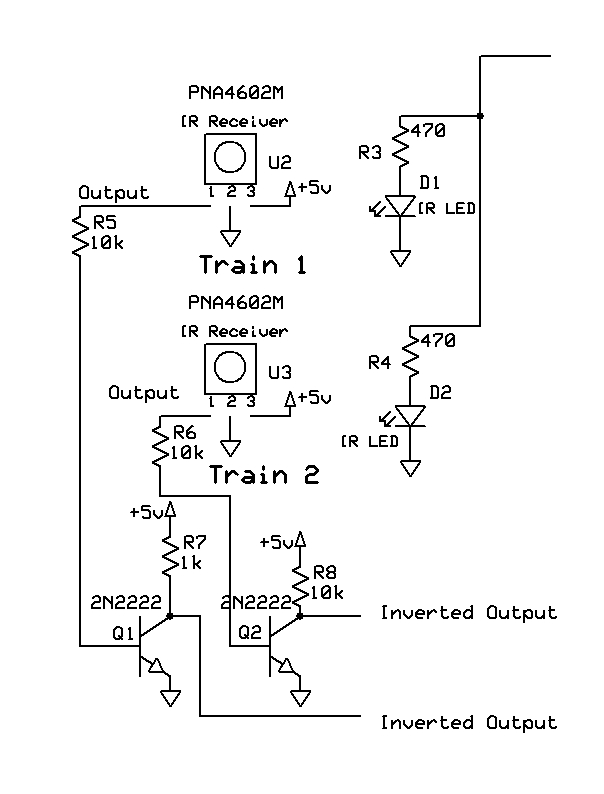
The schematic below shows a pair of reflective sensors and the signal inverting components. There are two emitter LEDs (D1 and D2) on the right and two IR detectors (U2 and U3) on the left. Transistors Q1 and Q2 invert the output from the PNA4602Ms so that the signal matches the output from the across-the-track sensors.
Across-the-Track Sensor Construction
In order to make the sensors water resistant and more immune to a frequently hostile outdoor environment they have been placed within a housing made of CPVC pipe. This is the type of plastic pipe that is commonly used for household water supplies. The pipe and fittings are inexpensive, tough and readily available at most hardware stores and home centers. They are also easily drilled and sawed.
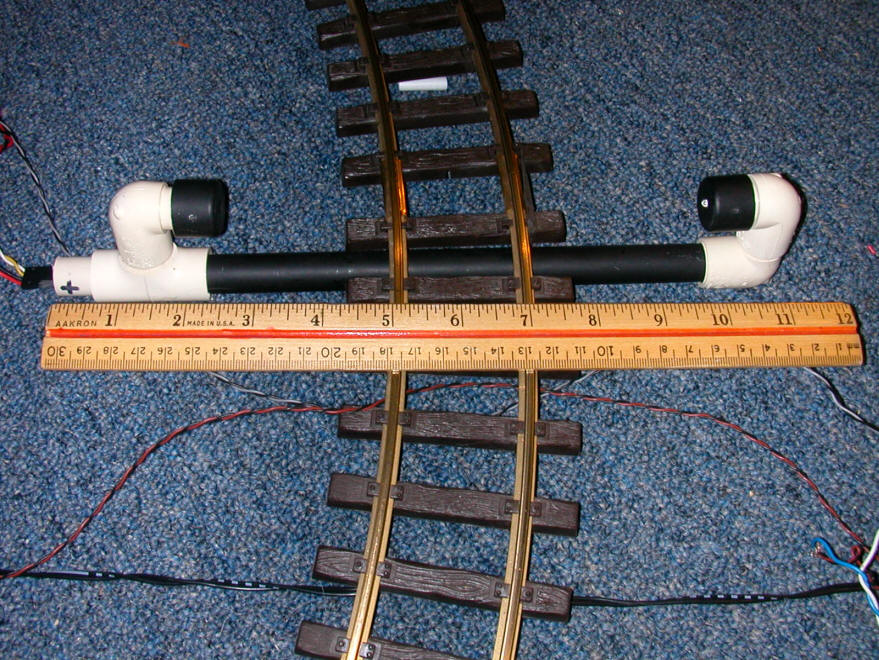
The across-the-track sensors are made up of an 8" section of 1/2" CPVC pipe and a number of fittings. The pipe section in the photo below is painted black as are the two 1/2" pipe end caps that have been drilled for the IR LED (right) and IR detector (left). The fittings on the right are two street 90's. Street 90's are fittings that will accept a piece of 1/2" pipe on one end and will fit into another 1/2" fitting on the other. The fittings on the left are a "T" and another street 90. In addition short 1" pieces of 1/2" pipe connect the street 90 to the "T" and bring the connections out of the left side of the "T".
<PHOTO OF PARTS before assembly?>
After wiring the sensors are sealed within the fittings with silicon sealant and the whole thing is glued together with CPVC glue. The opening at the left where the wiring emerges is filled with silicon sealant as well.
Reflective Sensor Construction
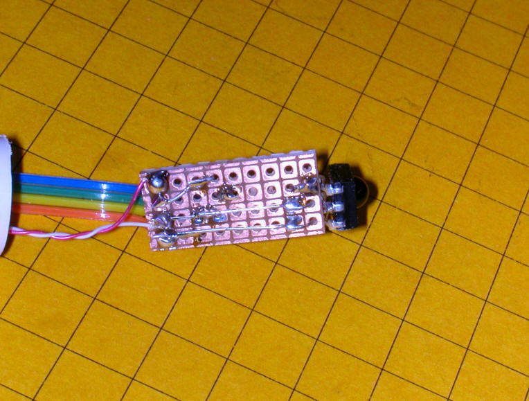
The reflective sensor mounts are also made from CPVC pipe. The detector, inverting transistor, a filter capacitor and several resistors are soldered to a small piece of circuit board as seen below. The sensor itself is the device at the right of the board.
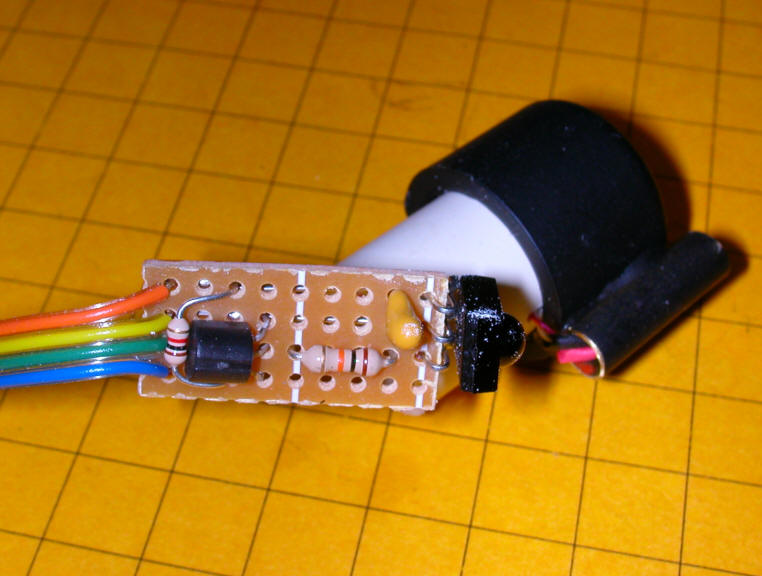
Here is a back view of the board showing the soldered connections.
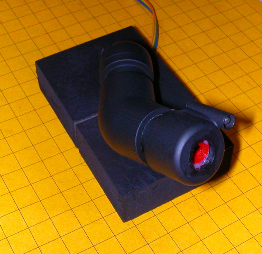
The sensor "sees" out of the cap through a piece of red Plexiglas that covers a hole in the end of the cap. In this photo you can also see the IR LED that is mounted inside of a small piece of brass tubing. Brass was used as infrared has a nasty habit of leaking through mounts that are made of plastic, even after it has been painted. The brass tube insures that the detector can never directly detect any emissions from the LED.
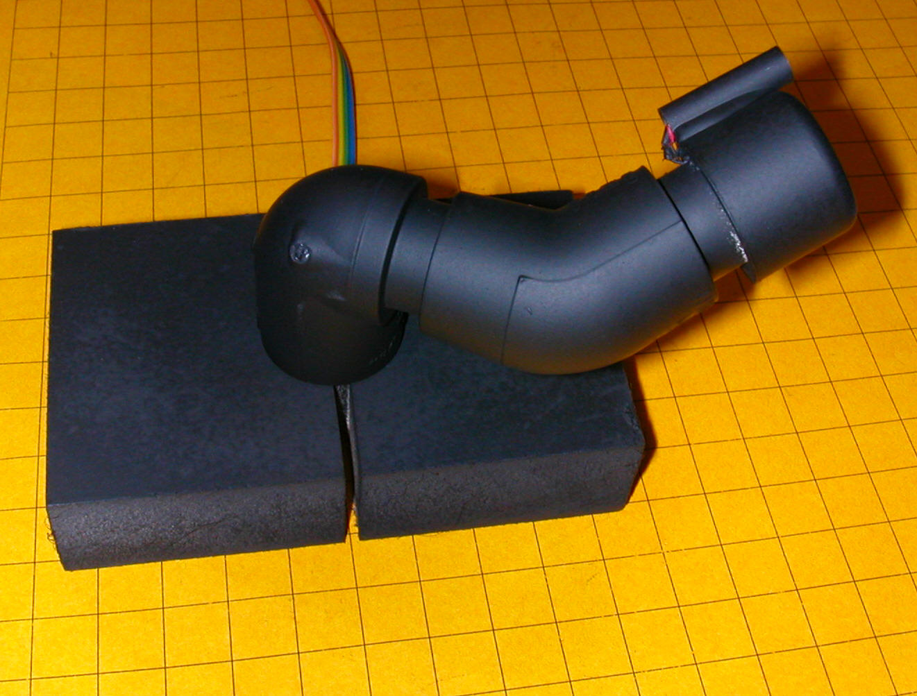
This photo shows the completed mount which is made up of the emitter & detector at the far right, then a small section of 1/2" pipe, a 45 degree fitting and a street 90 that fits into a 1/2" hole in the block of wood. Before gluing the fittings are adjusted so that the sensor points up a bit. When next to the track this angled placement helps to make sure that the sensor only detects a train on the nearest track rather than one that might pass by on a 2nd or 3rd track.
More Power!
The reflective IR sensor unit shown above does a great job of detecting objects that are up to about 18" away. This detection distance varies depending on the reflectivity of the passing object. A shiny white plastic boxcar can be detected at a much greater distance than a dull wood one.
The intensity of the IR LED's emissions, and thus the distance at which objects can be detected, can be increased by providing more power to the IR LED. This can be done by decreasing the value of the current limiting resistor from 470 ohms to a value closer to 100 ohms. Unfortunately you can't just change the resistor as the increased current flow will easily exceed the 20 milliamp capacity of the PIC's output pins. To protect the PIC a single PNP transistor, a 2N????, can be used to drive the LED. These transistors can handle more than 100 ma without any trouble. You may have noted this transistor, Q3, in the schematic above. Because it is already the option of using the smaller value resistor is there without any additional modifications.
Complete Circuit
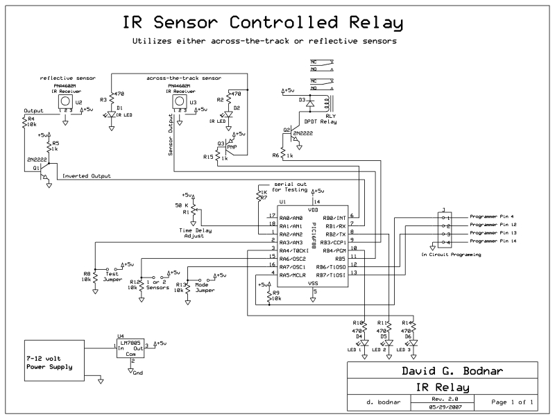
The rest of the circuit includes the microcontroller, a PIC 16F88, a DPDT relay, a potentiometer that is used to adjust event timing, three LEDs and three jumpers that are used to configure the software operation.
In the upper left are the two infrared sensors. D1 and U2 make up a reflective sensor and D2 and U3 make up an across-the-track sensor. Because each shows the same output to a passing train they can be interchanged as needed so that any combination of sensors can be used.
The DPDT relay in the upper right is closed when an event is triggered. The first jumper in the lower left is normally open. If closed for testing the relay is disabled so that the it is not constantly operated when placing and adjusting the sensors. The second jumper is left off if you are using only one sensor and placed on if two sensors are in use. The last jumper selects the mode of operation. If it is off the unit reacts to events by triggering the relay. If on the unit counts events and flashes out the total using the LEDs as each occurs. The potentiometer, R1, is used to set the amount of time that the relay stays closed after an event is triggered. Its use and the use of the jumpers is explained in more detail later on in the article.
Sensor Placement
The across-the-track sensors are placed so that the emitter and detector can see one another across the track. A passing train breaks the IR beam. There is an indicator LED on the circuit board that lights whenever the beam between the emitter and detector are broken. Take care to place the detector end of the sensor (the one where the connecting cable exits the pipe) so that direct sunlight does not fall on the detector.
<DIAGRAM OF NORTH/DETECTOR>
The reflective sensor is a bit more tricky to place. It is best to put it right next to the track with the sensor facing up at a 30-45 degree angle. This helps to insure that the detector only sees reflective IR that comes from a train on the track next to it. Again, take care that direct sunlight does not fall on the head of the sensor unit.
Operation and Configuration
1 sensor or 2
reflective or across-the-track
if 1 sensor:
- relay closes when sensor detects train
- pot determines time till relay opens (0 - 255 seconds) - this time can be customized to fit your needs
- connecting jumper 2 has relay close when the sensor is hit once and open when it is hit the 2nd time (pot sets minimum time relay stays closed so multiple cars don't cause a problem 0-255 seconds)
if 2 sensors
- relay closes when either sensor is first hit
- relay opens after 2nd sensor is hit
- pot determines time after 2nd hit for relay to open (0-255 seconds)
-
The detection system can be used with either 1 or 2 sensors.
If one sensor is used the relay closes as soon as the sensor is hit. The potentiometer is used to select the amount of time that must pass after the last detection before the relay opens. If one sensor is used and the mode jumper is closed the relay will close the first time the sensor is crossed and stays closed till it is hit again. The potentiometer sets a minimum time that the relay must stay closed before the 2nd hit opens it.
If two sensors are used the relay will close when either of the sensors is hit. The relay stays closed until the 2nd sensor is hit. The potentiometer sets a minimum time that the relay must stay closed before the 2nd sensor can open it.
There is also a test jumper. If this jumper is closed the relay is completely deactivated so that you can test the unit by watching the sensor LEDs on the board and not have the relay clicking on and off unnecessarily.
Examples
* One Sensor One Switch
Oval of track with a crossing siding. When the sensor
is first hit the relay closes activating the switch motor. The train
enters the siding. On the second loop through the oval the sensor opens
the relay moving the switch motor in the other direction. - NOTE may need
to add H-bridge to move switches - gang one chip for one switch
* Two Sensors One Crossing Signal
Track with train or car crossing. When first sensor is
hit the relay closes activating a crossing signal. When the 2nd sensor is
hit (and the time set by the potentiometer has passed) the relay opens stopping
the crossing
* One Sensor One Sound Unit
When the train hits the sensor the relay closes and a sound
device is activated to either announce a train's arrival or barnyard sounds or
whatever.
* One Sensor Stops Train In Block
When train hits the sensor the relay closes removing power
from a block of track, stopping the train. Once the time set by the
potentiometer has passed the relay opens restoring power to the block.
Note that the relay can only handle 3 amps and that the train will stop and
start suddenly. See <REFERENCE> for ways to decelerate and accelerate more
gradually. Note that the small relay on the board can easily be used to
trigger a larger relay that can handle a larger power load.
Conclusion
I hope this article has given you a good idea of how pulsed infrared sensors can be used to reliably detect trains and trigger events.
Additional Reading
Parts / sources
Radio Shack
All Electronics
Futurlec