| The objective of this page is to describe
a simplified controller for the incline that is described here: Working Model of the Duquesne Incline The original controller was a modified BARC auto-reverse controller. The BARC is an excellent unit but way too powerful and way too capable for the simple task of reversing an incline. The controller that is shown here does a few simple tasks:
|
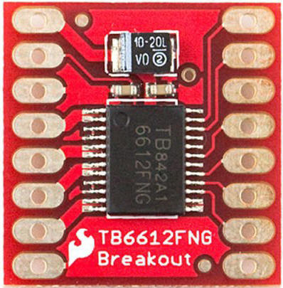
| Hardware The circuit centers around an Arduino Pro Mini or Leonardo micro-controller. This very capable device is small but more than powerful enough to control the incline motor. It has three inputs, two are potentiometers and the third is a sensor that detects the position of the incline cars. The small gear head motor is controlled by a very small H-Bridge that can be found on eBay or Amazon.
The schematic is here:
|
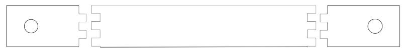
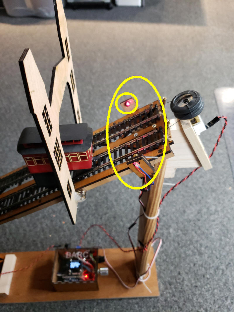
| Laser Sensor There are many ways that the Arduino could be wired to detect when one of the incline cars has reached the very top or very bottom of the track. Hitting switches or reflecting an IR beam come to mind. I opted to send a beam of light across the top of the two tracks at the top of the track. When that beam illuminates a photo-transistor the Arduino sees that the cars are going up and down. When one of the cars blocks the beam the Arduino stops the motor, pauses, reverses the motor and continues to run the motor. The simplest light source that I had handy was a small red laser diode that can be purchased from Amazon where 10 can be had for well under $1.00 each. The laser mount was designed in CorelDraw and cut on the laser cutter
Be sure to shield the phototransistor from ambient light. A small piece of black plastic or metal tubing around the phototransistor does a good job. |
| Operation Make sure that the laser is fully illuminating the center of the phototransistor. Adjust the Speed pot to have the incline cars run at an appropriate speed. Then adjust the Time pot to select the delay that is implemented when a car reaches the top of the track. |
| Software version INCLINE---V1-2--All_WORKING-LeonardoOnly /* d. bodnar - 3/25/19
2 Pots reading OK and speed pot determining speed
*/
char Ver[ ] = "1.2 ALL PARTS WORKING";
int i = 0;
#define DelayTime A2 //
#define CarSpeed A1 //
int DelayTimeValue = 0;
int CarSpeedValue = 0;
#define readLaser 3
int laserValue = 0;
int dir = 0; // direction
int accelDecelRate = 10; // speed of accelerate & decelrate
#define motor1 6
#define motor2 7
#define enable 8
#define chipSelect A0
#define motorPWM 9 // only on PWM: 3, 5, 6, 9, 10, and 11.
void setup() {
pinMode(motorPWM, OUTPUT);
pinMode(motor1, OUTPUT);
pinMode(motor2, OUTPUT);
pinMode(enable, OUTPUT);
pinMode(chipSelect, OUTPUT);
pinMode(readLaser, INPUT);
Serial.begin(115200);
Serial.print("INCLINE CONTROLLER " ); Serial.println(Ver);
digitalWrite(enable, HIGH);
digitalWrite(chipSelect, HIGH);
CarSpeedValue = analogRead(CarSpeed) / 4;
digitalWrite(motor1, LOW); // pull pin low
digitalWrite(motor2, HIGH);
accelerate();
}
void loop() {
DelayTimeValue = analogRead(DelayTime);
CarSpeedValue = analogRead(CarSpeed) / 4;
analogWrite(motorPWM, CarSpeedValue);
Serial.print("Laser / Delay / Speed ");
laserValue = digitalRead(readLaser);
if (laserValue == 0) {
decelerate();
dir = !dir;
if (dir == 0) {
digitalWrite(motor1, LOW); // pull pin low
digitalWrite(motor2, HIGH);
}
else {
digitalWrite(motor1, HIGH); //
digitalWrite(motor2, LOW);
}
delay(DelayTimeValue * 10);
accelerate();
delay(2000); // time to get past the laser
}
Serial.print(laserValue);
Serial.print(" / ");
Serial.print(DelayTimeValue);
Serial.print(" / ");
Serial.println(CarSpeedValue);
}
void accelerate() {
Serial.println("Accelerate");
for (i = 0; i < CarSpeedValue; i = i + 10 ) {
analogWrite(motorPWM, i);
delay(20);
}
Serial.println("done");
}
void decelerate() {
Serial.println("Decelerate");
for (i = CarSpeedValue; i > 0; i = i - 10) {
analogWrite(motorPWM, i);
delay(20);
}
analogWrite(motorPWM, 0);// stop completely no matter the step
Serial.println("DONE");
}
|
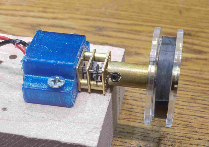
| The motor and pulley are shown here.
The blue plastic part is a hold-down clamp for the motor. The
black material around the pulley is bicycle inner tube that can
improve friction between the pulley and the "cable".
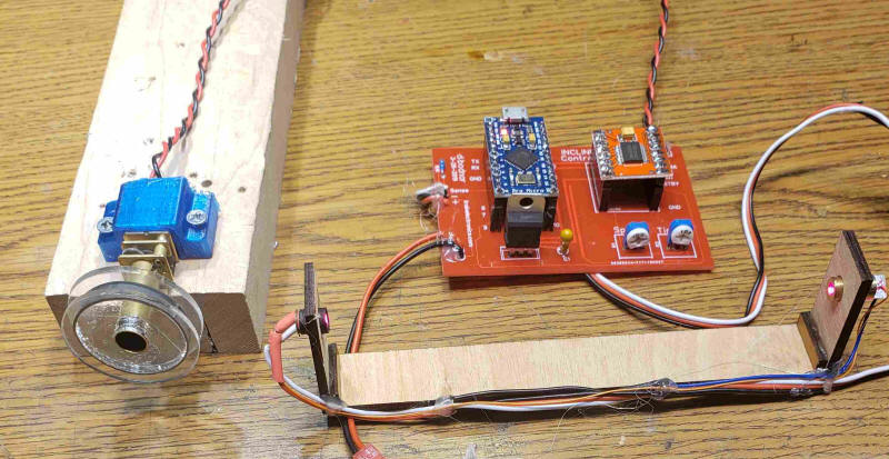
This photo shows the motor, control board and sensor. The potentiometer on the left adjusts the speed of the motor. It is best to keep that low. The pot on the right adjusts the length of time that the motor stays off at the end of each trip.
|