| Introduction A few months ago Noel Widdifield contacted me about helping him to connect a set of 10 signal crossing lights to each of his 10 turnouts so that the appropriate LED would light indicating the orientation of the switch. The signals were from Shiloh Signals. Each signal contained one green and one red LED. After corresponding with the folks at Shiloh I found that each signal had 3 wires coming from it. One wire goes to the cathode of the red LED, one wire goes to the cathode of the green LED and one wire connects to both of the anodes of the LEDs which are connected together within the signal. In a setup like this you simply connect the positive voltage from your DC power supply to the common anode lead and connect the negative terminal to the cathode of the LED that you want to light. This type of LED wiring is called, for obvious reasons, "common anode" wiring. As mentioned above, we would have used LGB's 1203 units had they been readily available. Since we could not find a source for ten 1203's other methods were explored. How LGB's Switch Unit Works The LGB 1203 is a DPDT (Double Pole Double Throw) add-on device that attaches directly to the end of the LGB turnout motor. It is made up of two identical SPDT (Single Pole Double Throw) switches that are thrown one way or the other depending on the switch motor's position. To install this unit a cover pops off of the end of the switch motor and the 1203 is added. As one would expect there are six wire connection terminals on the 1203. Two terminals are common, two are normally open and two are normally closed.
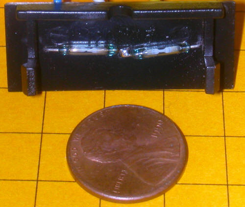
Alternatives to Using the 1203 A number of alternatives were explored when seeking a solution to this problem. Among them were using small SPDT micro switches similar to those used by LGB. Since we are only interested in controlling one signal light (containing 2 LEDs) a single SPDT switch is all that is necessary. Although small switches are available this solution was rejected due to the difficulty in aligning the switch properly so that it reliably indicated the position of the switch. The preferred solution uses one or two magnetic reed switches. Some reed switches are so small that they can easily be installed inside of the end of the LGB switch motor. This allowed us to use the cover that is normally removed when the 1203 is installed to mount the reed switches and any other components. In this photo you see the end plate from an LGB switch motor that has a small reed switch mounted on it. Another reed switch is below the penny. Note that this end plate is included with every LGB switch motor and is normally removed and discarded when the 1203 is added.
This is a view of the inside of the turnout motor cover showing the two reed switches that, when wired together, comprise a SPDT switch. If you look carefully you will note that the two inner contacts are soldered together.
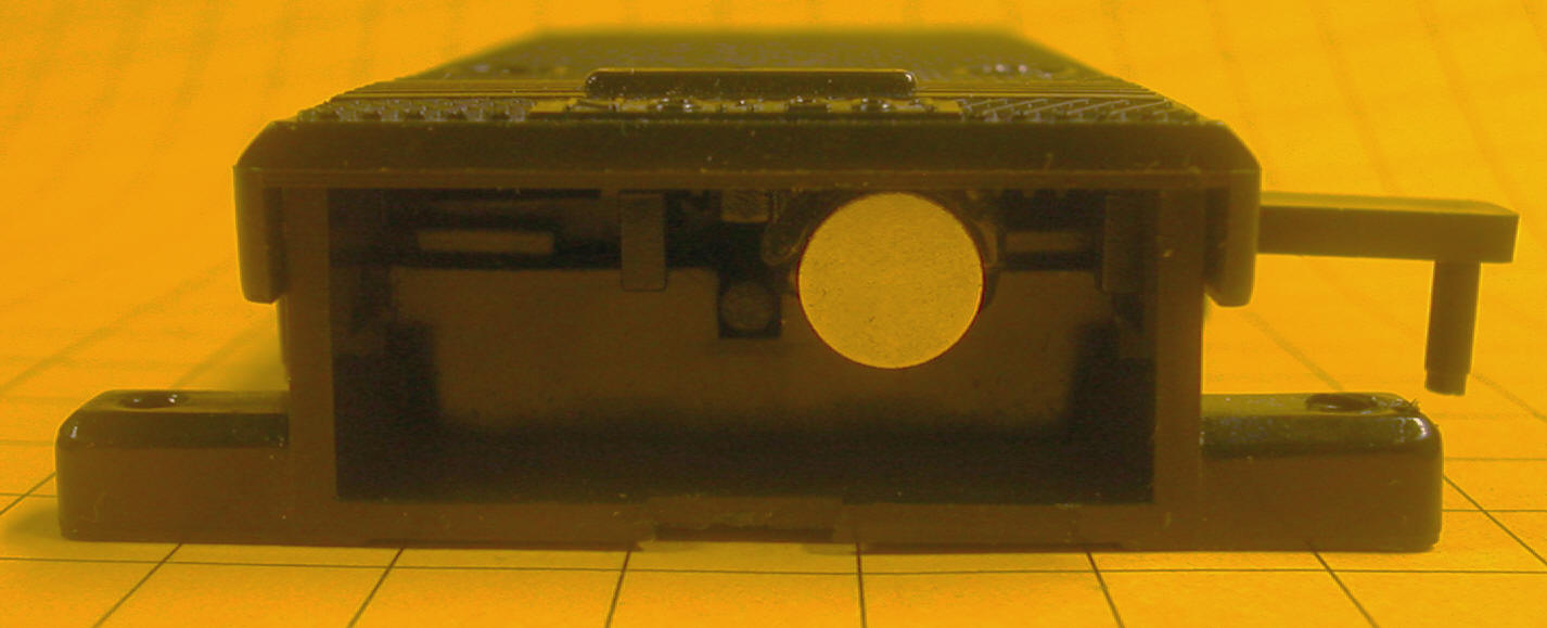
The only other modification to the switch motor is the addition of a small permanent magnet to the arm that moves inside of the switch motor. This arm moves left or right when the switch is thrown. In this photo the magnet is the silver object to the right of center. Note that the switch throw arm is also to the right. When the switch throws the other way the arm and magnet both move to the left. The magnet is glued to the center of the movable arm with a small amount of epoxy.
Wiring with Two Reed Switches The wiring diagram below shows how the signal lights are wired if two reed switches are installed inside of the switch motor. The two reed switches are wired together so that they act as a single SPDT switch. When the magnet moves to one side switch SW1 is turned on and SW2 is off. When it moves to the other side SW1 is off and SW2 is on. The 1000 ohm current limiting resistors (R1 and R2) are installed within the signals themselves.
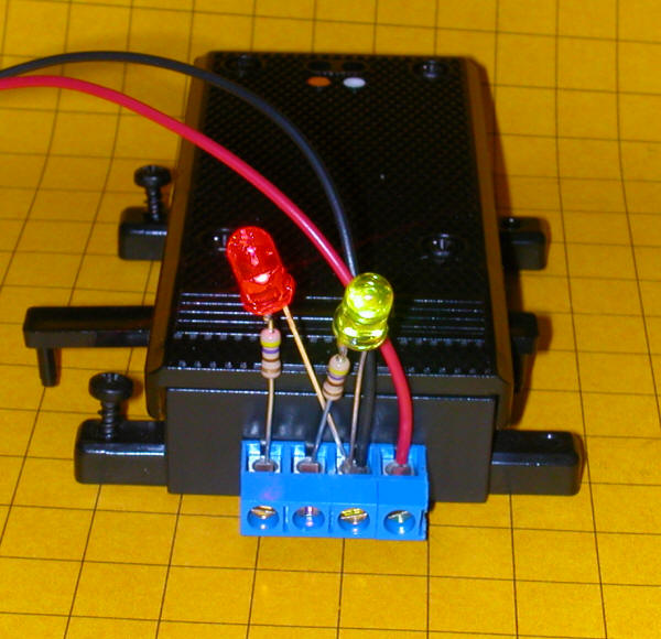
The parts to the left of the 4 terminal connector are inside of the end plate on the switch motor. The terminal block is installed on the outside of the end plate. Here we see two test LEDs and the red & black connections that supply 12 volts DC.
Only three of the four wires from the signal are connected to the circuit. This is due to the wires from cathodes of the two LEDs being tied together at the signal. Note that this wire and the negative terminal of the battery or power supply both go to connection #2. The positive power connection goes to #1. If the LEDs do not light in the proper order, that is if the red LED lights when the green one should be lit, just switch the connections at #3 and #4. Another Wiring Solution The above circuit uses two reed switches to make up a SPDT switch. I found that both reed switches can be activated if the magnet that is glued to the movable arm is too strong. A more reliable system uses only one reed switch that can be placed far to one side of the base plate. The wiring diagram below shows how it is wired. The parts to the left of the 4 terminal connector are inside of the end plate on the switch motor. Resistors R1 and R2 make up a voltage divider that supplies approximately 1/2 of the supply voltage to terminal 4. Note that the two LEDs are wired in parallel with anode to cathode and cathode to anode. Resistors R3, R4 and R5 are current limiting resistors. Their values can be modified if the LEDs have internal current limiting resistors. When reed switch SW1 is open the red LED lights. When SW1 is closed the green LED is lit.
The only disadvantage of using this circuit is that you must adjust the values of the resistors to get both LEDs to light with the same intensity. Due to the internal wiring of the Shiloh signals this circuit would not work in that application. Another Circuit for One Reed Switch A single transistor can be used to create a circuit that will also operate from one reed switch. This circuit has proven to be the most reliable and has given the best performance. Please note that this circuit works only with LEDs that have their cathodes wired together. See the notes at the end of this article for a revised circuit that will work with common anodes.
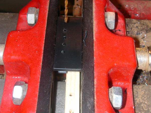
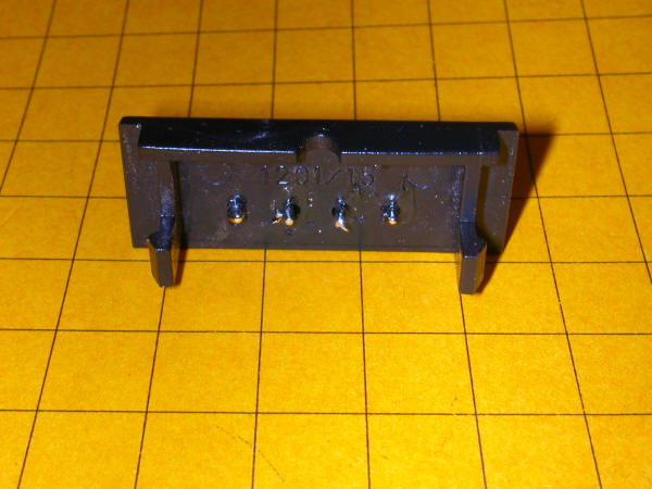
When reed switch SW1 is open the green LED is lit as power goes to it through resistor R3. When SW1 is closed power goes directly to the red LED lighting it. Transistor Q1 acts as an inverter and shorts the green LED's anode to ground extinguishing it. These step-by-step photos show how the components are mounted inside of the end plate of the turnout motor. 1. Use the 4 pin block connector to mark the end plate for drilling
2. Drill four 1/16" holes about 1/4" up from the bottom of the end plate.
3. Insert the block connector
4. Tin the pins with solder
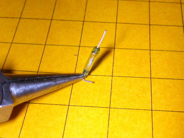
5. Carefully bend the leads on the reed switch. DO NOT bend while holding the glass body of the reed switch. It WILL shatter! Always bend while holding the wire with pliers.
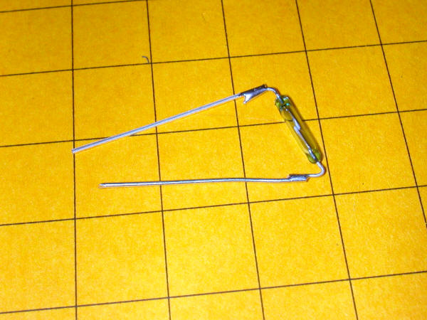
6. Extend the length of the reed switch's leads by soldering on scraps of bare wire.
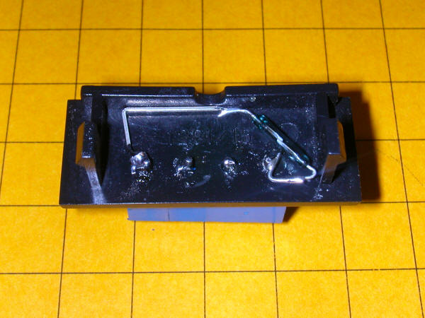
7. Solder the reed switch in position as shown below.
The connection on the right is pin 1, the one at the far left is pin
4.
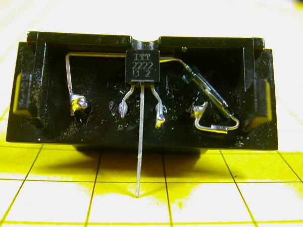
8. Solder the NPN transistor as shown below. The emitter goes to pin 3 and the collector goes to pin 2. In this photo the base of the transistor is not yet connected.
9. Bend and shorten the base lead on the transistor as shown.
10. Solder the 10 K resistor between the base of the transistor and pin 1. (see the close-up photo at the end for another view of this connection)
11. Solder the 1 K resistor between pins 2 and 4. (note to those of you who are paying close attention: The color code on the resistor shows that it is not a 1K but a 470 ohm. Either will work in this application.)
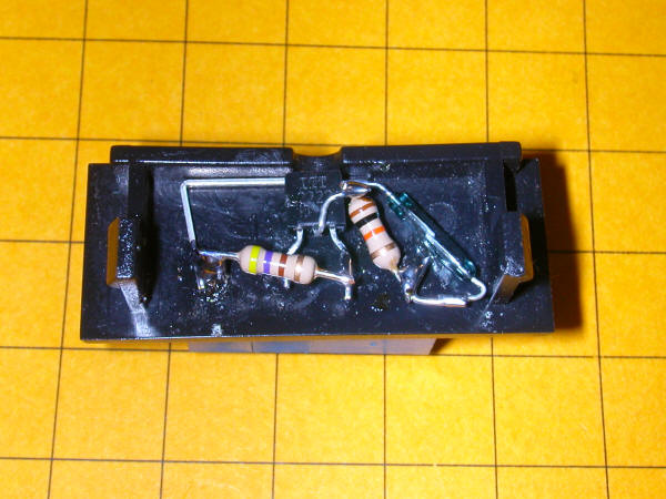
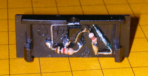
12. Here is another view of the finished circuit.
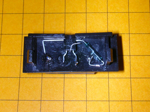
13. Some of the connections can be seen more clearly from this
angle.
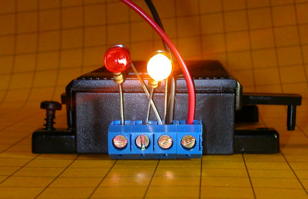
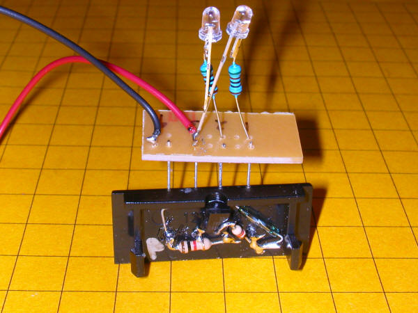
14. Insert the base plate into the turnout motor and test for smooth operation. 15. Test the unit by inserting LEDs into
the connector as shown. Note that each LED has a current
limiting resistor soldered to its anode (positive) lead. The
red and black wires are the positive and negative connections to a
12 volt DC power supply.
When the control arm is moved to the left the red LED lights.
Circuit for LEDs Wired with a Common Anode The circuit and wiring procedure shown above will only work when the two LEDs are wired with their cathode (negative) leads wired together. If your LEDs are wired with their anode (positive) leads together this circuit will work. It is the same except for the orientation of the LEDs and battery and the use of a PNP transistor rather than an NPN transistor.
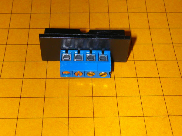
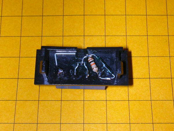
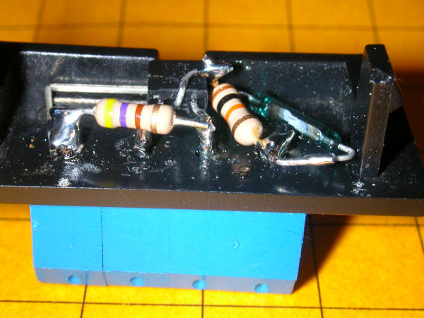
Here is a photo of the completed PNP unit.
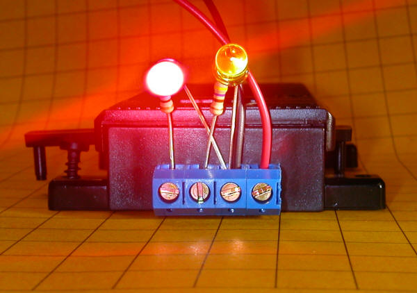
Here we see a small test board that has two LEDs and positive and negative power leads that was used for testing.
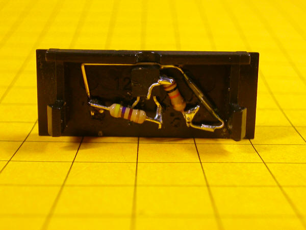
Here is a front view of the test board. It also clearly shows how to wire the signals. The cathode of one LED goes to terminal 1. The cathode from the other LED goes to terminal 2. Both of the LED's anodes go to terminal 3 along with the positive 12volt power lead. The negative power lead goes to terminal 4.
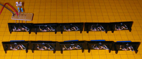
Ten PNP units were needed. The test board is also shown.
Parts List
|