| I have been using various on-line services
to fabricate professional circuit boards from my designs for nearly
20 years. While these boards are reasonably priced and
superbly fabricated there are times when I just need one or two
simple boards and I don't want to wait days or weeks for an order to
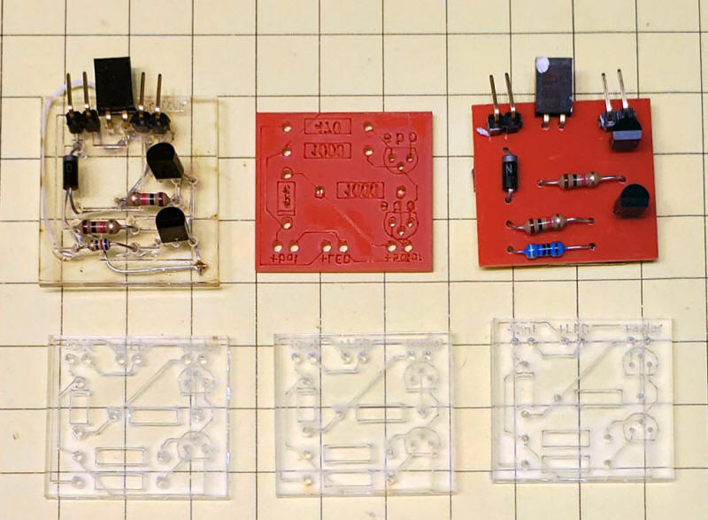
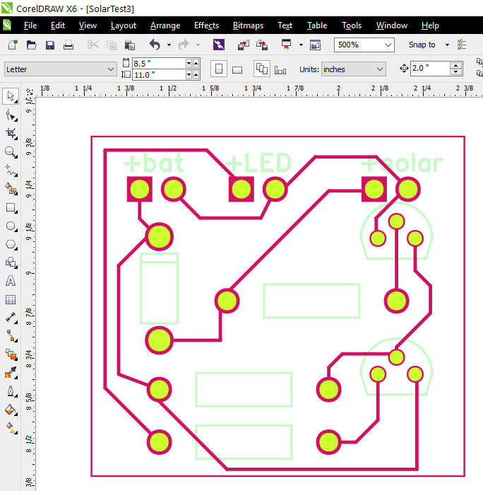
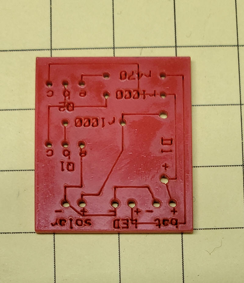
be delivered. I have two laser cutters and have always wondered if they could be used to make circuit boards. A quick Google search turns up a number of ways to do this but all required chemical etching, something that I did not want to do. They also needed to be manually drilled. The method that I will describe here does not give you conductive traces but does provide drilled holes and guides for point to point solder connections. It is also ideal for proofing a new board design as you can insert all of the parts into it and test the layout and fit. These photos show the computer files and several views of the finished board.
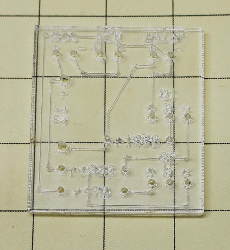
The boards are shown using both clear acrylic and red/white acrylic that is commonly used for cutting labels or ID cards.
|
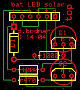
| Circuit Design The circuit shown above is a simple, one-sided board that I designed many years ago to control solar operated garden lights. It has three connections, one to a battery, one to a solar panel and one to the LEDs. When the sun is out the battery is charged from the solar panel and the LEDs are not powered. When the sun goes down the battery powers the LEDs until dawn. The circuit is explained in more detail here: http://www.trainelectronics.com/artcles/Solar_power_4_LED_lights10-29-04.htm
While it might be possible to create double sided prototype boards using this method I have limited myself to single sided designs as it would be quite difficult to solder to many components from the top. You could, of course, use insulated wire on the back for the second "layer" of the board. |
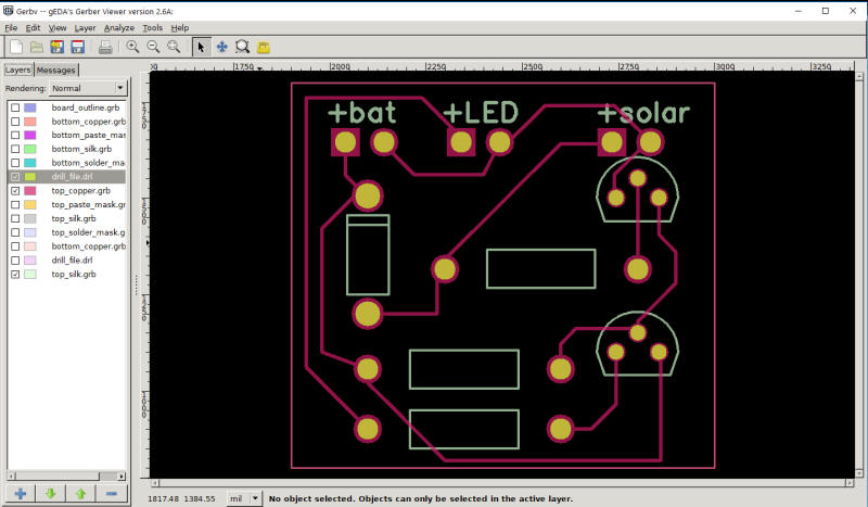
| Design Software Boards can be designed using any program the creates Gerber files. I use an outdated program called "FreePCB" but don't recommend it to others as it is buggy and hasn't been supported for many years. Once a design is complete export it as a set of Gerber files that might look like this:
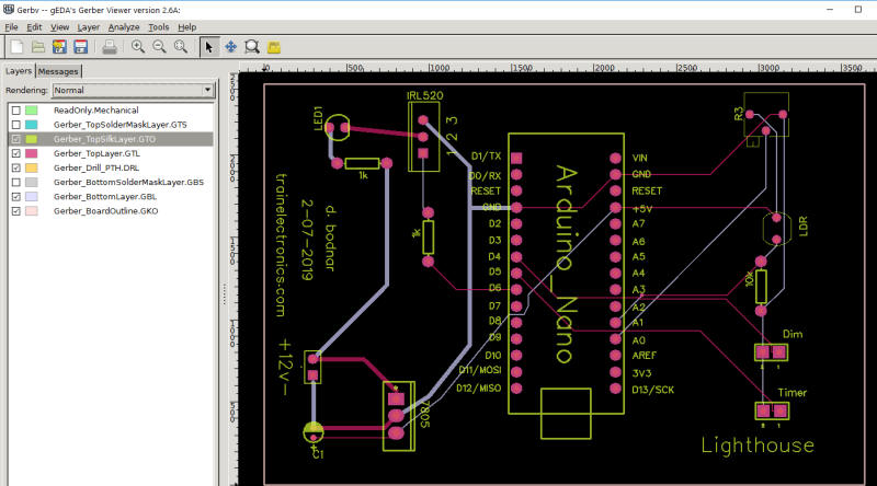
Load the Gerber files into Gerbv, a free, open source program that will allow you to get the Gerber files into CorelDraw, the program that is used to format designs for the laser cutter. NOTE: Even though I am using CorelDraw to get the files into my laser cutter I am sure that other vector graphic programs have similar capabilities for other laser cutters.
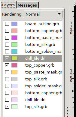
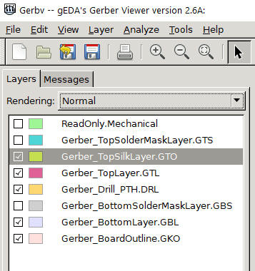
Only a few of the Gerber file layers are needed. Here are the ones I used, "drill_file", "top_copper" and "top_silk". Note that only these are checked.
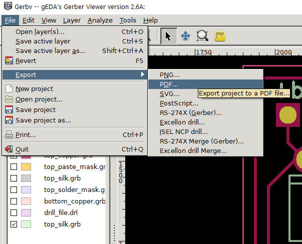
Send these layers to PDF by clicking File / Export / PDF
|
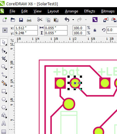
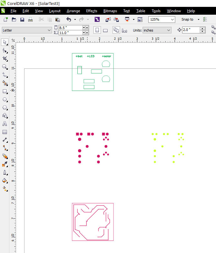
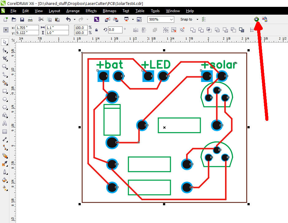
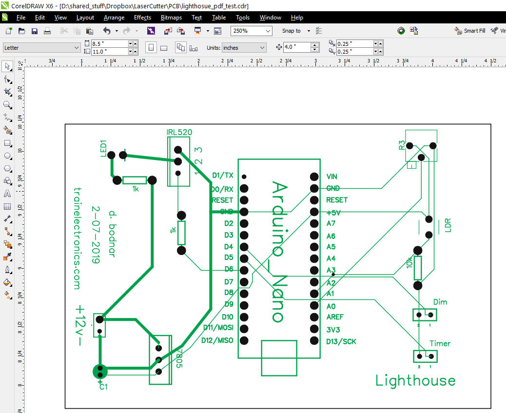
| Open a blank drawing in CorelDraw (I am using version X6 but these steps should work with other versions) Import the PDF file created above. Once it is in CorelDraw click on it and select Arrange / Ungroup
Select the inside of a hole
Click: Edit / Find & Replace / Find Objects (or use CTRL -F)
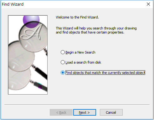
Select "Find objects that match the currently selected object"
Next then Finish - this box will be displayed
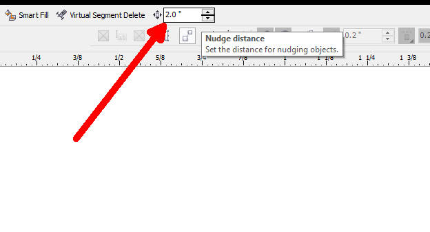
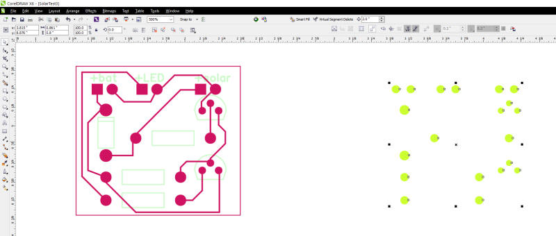
choose Find All then click the X in the upper right to exit Arrange / Group (or CRTL-G) Set Nudge Distance to 2"
Press the Right Arrow Key to move the holes to the right.
Repeat with other colors moving them up, down or left to separate all of the layers
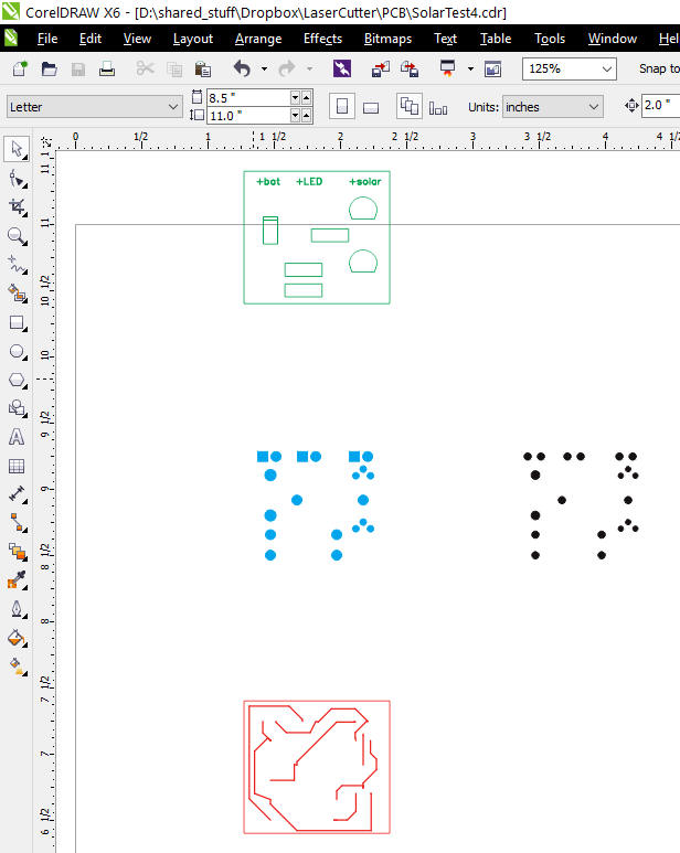
To make the images easier to see I changed the colors to black, green, red and blue
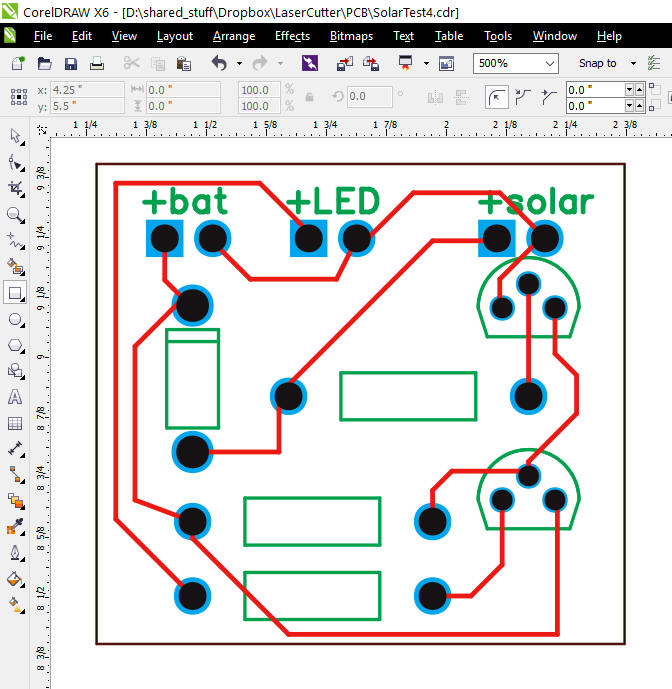
Return the separate groups to the center so that we can send one image to the laser cutter. Select each group, one at a time, and use the arrow keys to return them to the center. I also added a black box around the whole thing as black will be the color that cuts clear through the acrylic.
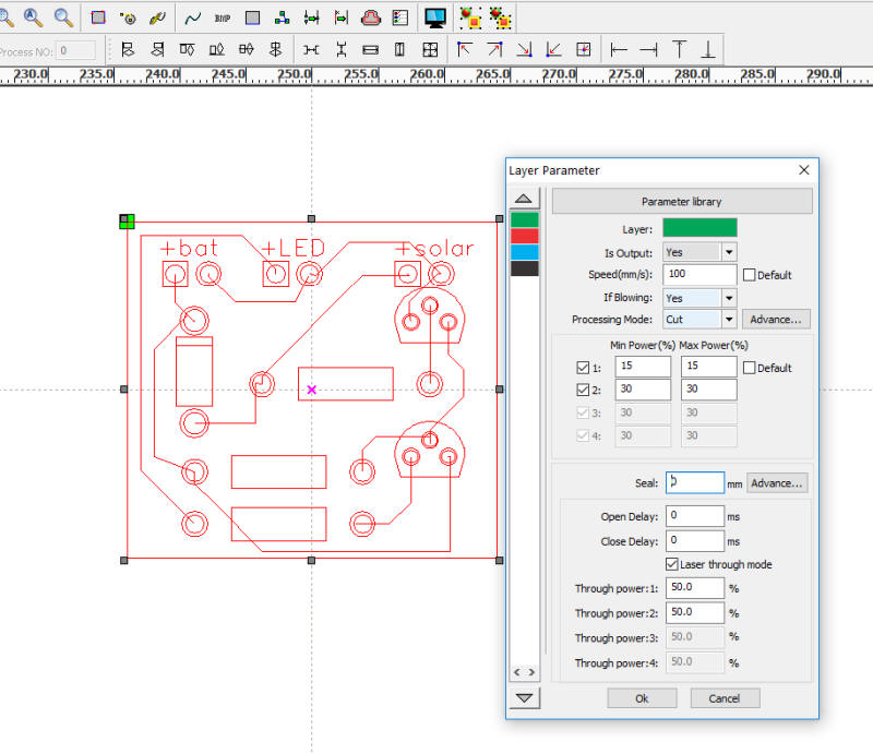
Select all of the above layers and transfer to Thunder Laser, the laser cutter's control program.
If you are using something other than Thunder Laser you can export the selected items as PDF or some other appropriate format. Set the power so that the holes and outline are cut through and that the wires and labels are only cut or etched part way through.
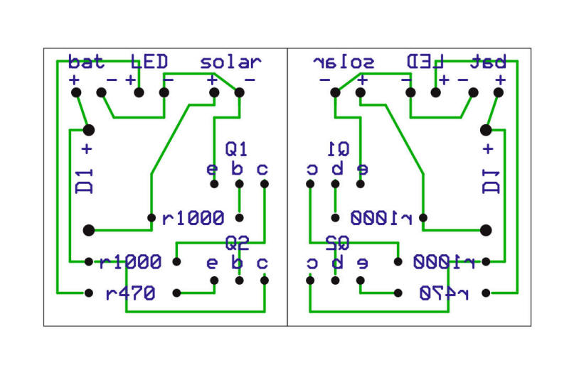
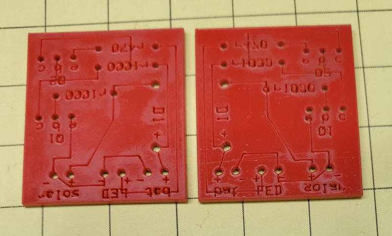
Here you can see the laser cut result. The wire patterns and labels are on the top of the board. That may make it more difficult to do wiring from the bottom so I frequently will "mirror" the image as shown below.
Here you can see the normal print (on the left) and the mirrored print on the right.
Of course, if you cut clear acrylic it doesn't matter which image you use as you can see through to the front or back easily
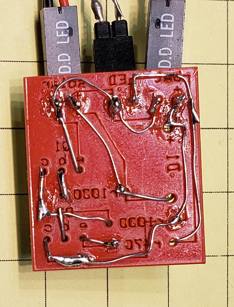
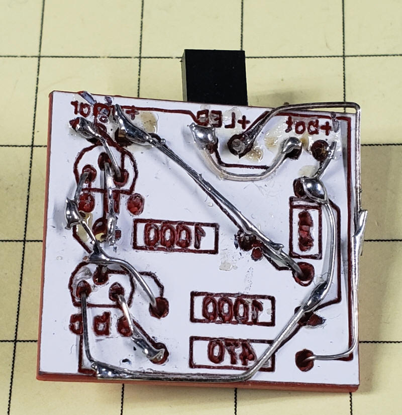
Once the components have been inserted wiring is simply a matter of connecting leads according to the etched wire guides.
|
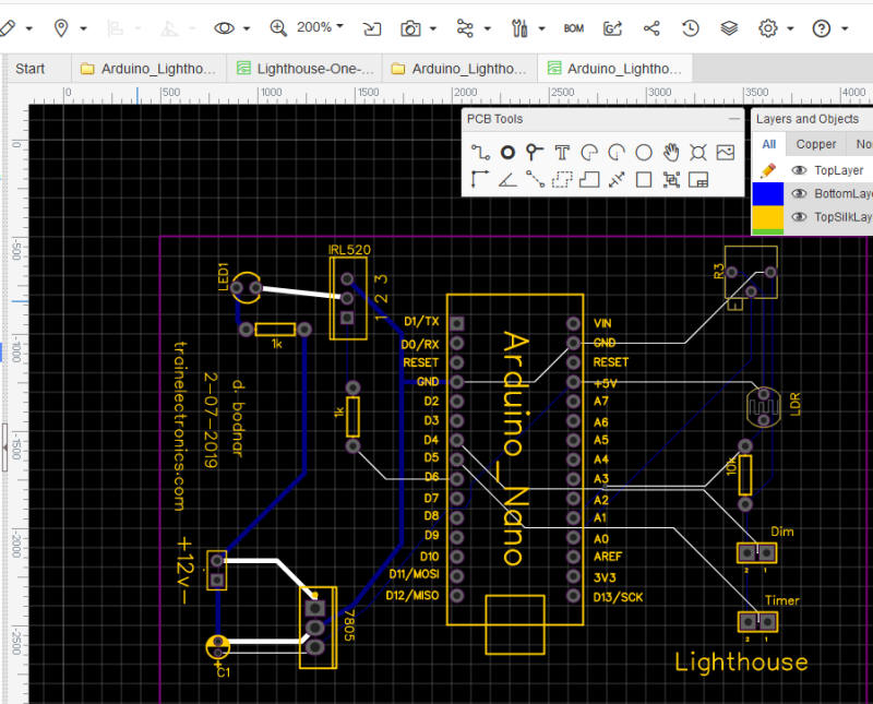
| I have also used
EasyEDA, shown below,
to create circuit board designs and Gerber files.
Again, import the Gerber files into Gerber Viewer to create a PDF for CorelDraw.
|