Mars Lights
Revised 10-24-10
& 6-17-2020
|
This circuit utilizes a microcontroller to simulate the unusual behavior of Mars lights. These bright headlights were installed on locomotives a few decades ago in order to make them more visible. Mars lights rotated in a horizontal figure "8" pattern projecting their beam left, right, up and down. |
Click here to jump to sample Videos
Click here to jump
to info on the revised circuit board
I have never been one to shy away from a challenge and one was presented to me a few months ago by one of our LSOL members. After seeing the article I wrote on ditch lights, John Damkier asked me if I had ever considered making an electronic version of a Mars light. Being something of a novice when it comes to railroad trivia I didn't have a clue as to what a Mars light was. After John enlightened me, he and I and a number of other visitors to the LSOL forums bounced around design ideas. (Visit the forum thread by clicking here.)
Before going into detail about how my Mars light implementation works I should give a little bit of background on full scale Mars lights. As I understand it they were a 2nd headlight that was frequently mounted at the front of steam or diesel engine during the transitional years when both types of engines were in use. The light was a bright spotlight that was mechanically moved up and down and side to side following a horizontal "8" pattern, something like the symbol for infinity, "∞." The objective was to make the engine more visible at crossings and to give the engineer a wider view of what was in front of the train.
There are a number of resources on the web that give information on Mars lights should you like to read more about them. The two below will get you started:
http://www.trainweb.org/gyra/mars.htm
http://www.trainweb.org/gyra/warnlts.htm
FIRST EXPERIMENTS
Making Mars lights with the use of motors and other mechanical devices was discussed in the forums but I decided to focus on a design that did not depend on any mechanical parts to move the light. I thought that a fully solid state unit with no moving parts would be less expensive, more reliable and smaller.
My initial thought was to reuse something that I had already done. Some weeks before our discussions on the Mars lights I had published an article on LSOL that described a circuit that used two LEDs to create a nice representation of flashing ditch lights. This circuit pulsed two bright white LEDs so that one increased in brightness as the other dimmed. By placing the two LEDs right next to each other a very crude representation of the Mars light was produced. It was a good start but it only simulated the side to side motion of the Mars light. The up and down component of its movement was missing. I could see that more than two LEDs would be needed to provide a reasonably realistic simulation.
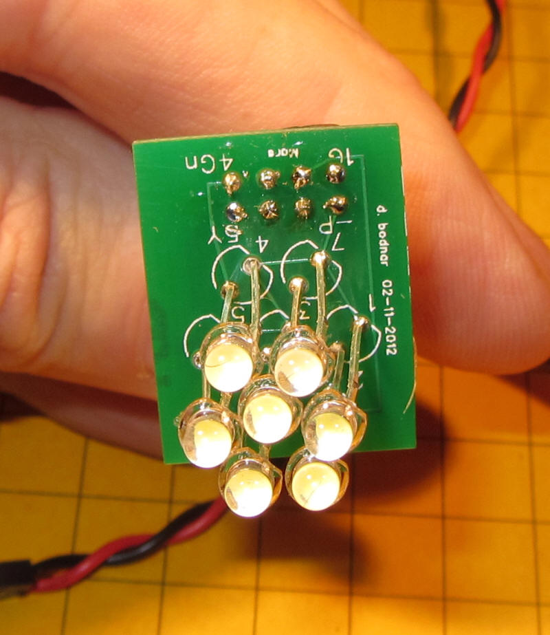
Rather than adding LEDs one or two at a time I decided to make the jump from the two LEDs used in the first experiment to an array of 7 LEDs that I felt had the potential to give a more accurate Mars light display. The 7 LEDs were arranged so that there were three in a horizontal row with two centered above and two centered below. Since the size of the complete light was sure to be an issue it was fortunate that this turns out to be the most compact way to arrange this number of round LEDs. I also opted to begin my experiments with 3 mm LEDs as they are the smallest bright, white LEDs that are readily available and are fairly easy to work with.
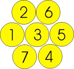
Next a lighting sequence needed to be determined. The numbers in the image will help you to visualize what I used. First LED 1 is powered up to full brightness then dimmed. As it dims LED 2 begins to brighten. When LED 2 is fully illuminated it begins to dim as LED 3 brightens. This brightening and dimming continues following this sequence:
1, 2, 3, 4, 5, 6, 3, 7, 1 and so on. Other patterns are discussed below.
SPEED CONTROL POTENTIOMETER
The 7 LEDs worked very well. Next I added a potentiometer to the circuit so that the speed of the transition from one LED to the next could be adjusted. Not only did this give a more configurable light but it also allowed me to more easily observe the LEDs behavior when I was exploring other patterns for the LEDs to follow.
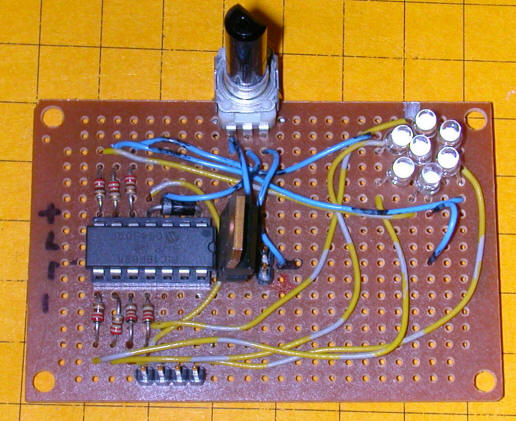
The first prototype circuit board is shown below. The microcontroller is the object just left of center. To its right is a 7805 voltage regulator that provides a consistent 5 volts to the system. The speed control potentiometer is at top center and the array of 7 LEDs is in the upper right corner. Note that there are 7 small resistors around the microcontroller. As you may have guessed they limit the amount of current going to each of the LEDs.
The schematic for the circuit is below. You will note that the microcontroller that is shown is not the PICAXE that I generally use for such projects. In this implementation we need to be able to utilize PWM, pulse width modulation, on as many as 7 different LEDs. Although the PICAXE 18X chip is able to do this it cannot execute its program with as much speed as the 16F684 microcontroller. The PIC chip used here is somewhat more difficult to program than the PICAXE but it is much better suited to this task.
FOUR LED EXPERIMENT
Although the 7 LED Mars light looked like a winner I was concerned that it might be too big for installation in some engines. The LEDs that I am using are 3 mm in diameter. As you can see from the diagram of the 7 LED array the light's largest dimension is 3 x 3 mm = 9 mm. This is about 0.35" or just a bit over 1/3 of an inch and that is only if you grind off the flange that is at the base of each LED.
A smaller array can be made by arranging four LEDs in a diamond pattern as illustrated below.
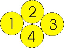
As with the 7 LED array LED 1 dims as LED 2 brightens following this pattern: 1, 2, 4, 3, 2, 4, 1, ...
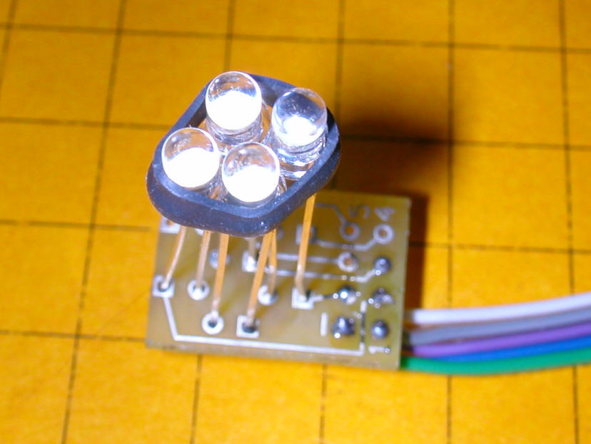
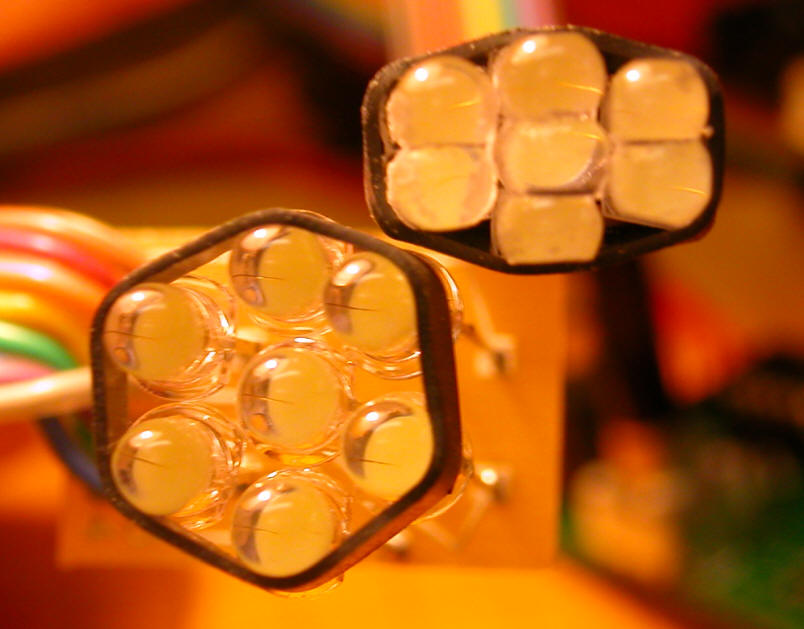
This photo shows four 3 mm LEDs. They are held in position by a small ring of heat shrink tubing.
I showed both of these sample Mars lights during my presentation at the National Garden Railway Convention in Santa Clara in July. When viewed from a distance of 10 or 15 feet members of the audience didn't even realize that there were two different LED arrays, one using 7 LEDs and the other just 4. Most thought that they were the same.
CUSTOM CIRCUIT BOARD
Based on the number of folks who had expressed an interest in the Mars lights I decided to design a custom circuit board and have them produced before I wrote up this article. While working on a design I added a few features that I thought would make the boards more useful. First, I designed the board and chose a microcontroller chip that would support either 4 or 7 LED arrays. This would allow the same board to be used for both designs. After assigning 7 pins, one for each LED, and an 8th pin for the speed control pot I still had three pins that were unused.
I decided to connect those extra pins to a set of three jumpers on the board that could be used to set configuration options. One of the jumpers tells the program whether it is working with 7 LEDs or just 4. The other two jumpers are used to determine which display pattern the LEDs use. This allows the end user to change not only the number of LEDs but the pattern that they use without doing any programming! You can see the circuitry for these jumpers on the schematic diagram.
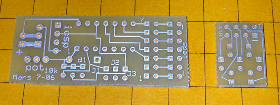
The finished boards are shown below. The main board is to the left. The smaller board is for the LEDs themselves. I decided to use two separate boards so that the LEDs might fit into the limited space available in the front of engines. For the 7 LED system an 8 conductor wire is used to connect the two boards. The 4 LED unit only requires 5 conductors in the connecting cable. The cable can be as short as an inch or two and as long as several feet.
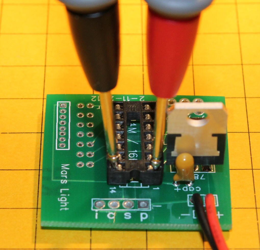
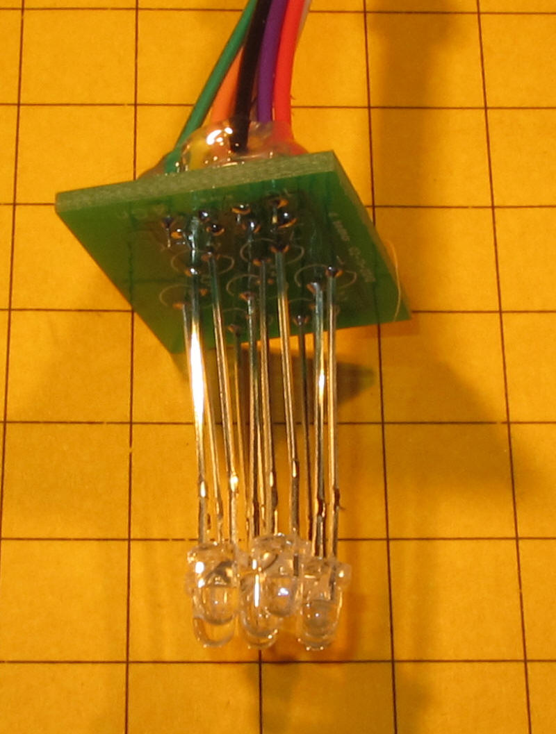
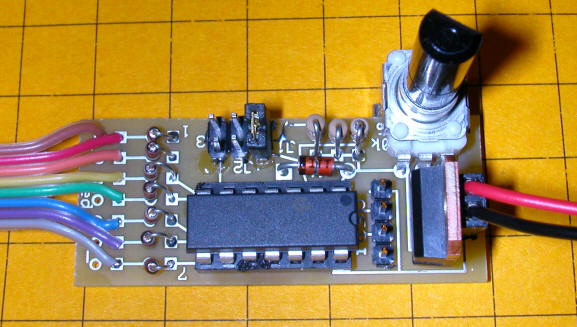
The completed circuit board, wired for 7 LEDs, is shown below. The power (red and black wires) comes in from the right. DC from 7 to 25 volts is used. The pot in the upper right is for speed adjustment. In this example I used a large pot for ease of experimentation. The rest of the boards that I make will have smaller pots that can be adjusted with a small screwdriver.
The cable to the left goes to the LED array that is in the next photo. The option jumpers are top center. Only one, labeled "j1" has a jumper on it in the photo. The 7 current limiting resistors are just to the right of the colored cable.
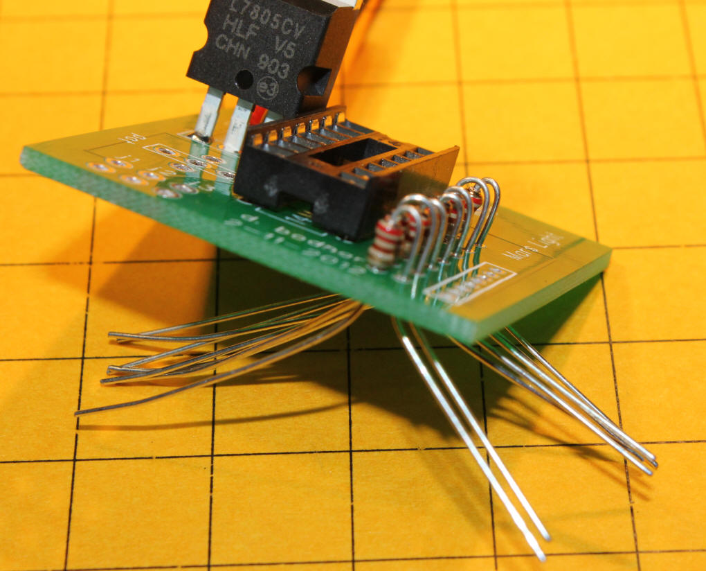
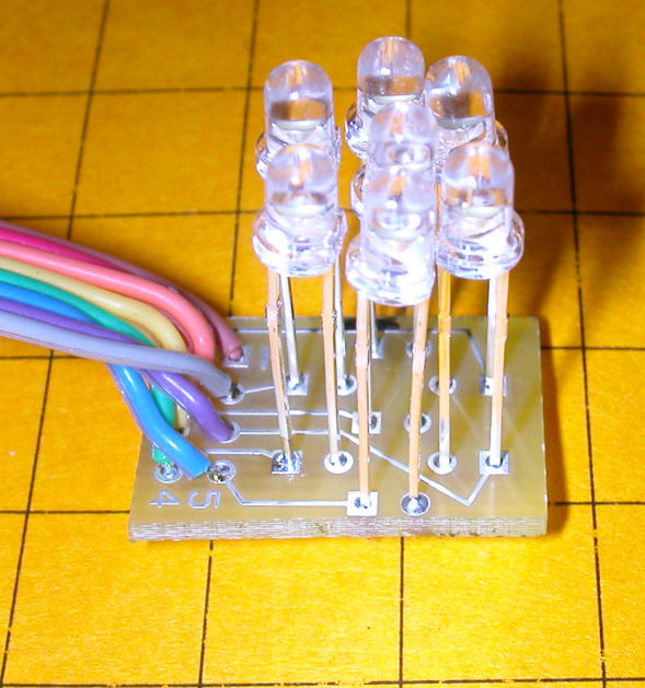
This side view shows how the LEDs can be mounted a short distance "off" of the board. Leaving the leads like this will allow you to experiment with directing the light from various LEDs to the sides, top and bottom. One does, however, need to take care not to allow adjoining bare wires to touch!
SIZE ISSUES
As you can see from the photo above the array of seven 3 mm LEDs takes up a good bit of space, even when aligned in the most compact pattern. Although there is plenty of room in a number of diesel locomotives for this array I experimented with ways to make the 7 LED array even more compact.
First I ground off the small flange at the base of each LED. That allows them to be mounted very close together so the array's diameter is 9 mm or about 3/8 inches. This will increase a bit if you focus some LEDs to the sides but it will still be a size that will work with many installations.
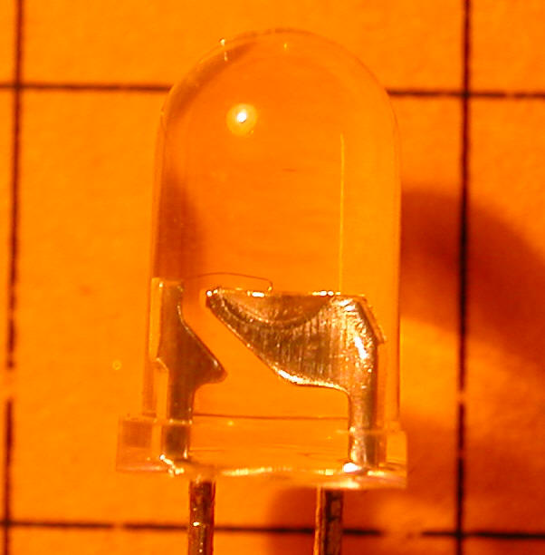
Next I reduced the LEDs size farther by grinding off the sides that were parallel to the LED's internal components. To determine where to remove excess plastic it helps if you first explore the anatomy of an LED.
In the photo below you should be able to see the inner components of a typical 3 mm LED. The wire on the left is the positive terminal or anode. The other terminal is the cathode, the negative connection. At the top of the cathode you can see what appears to be a dish with a tiny wire extending from the anode to its center. The dish is actually a reflector and the diode junction that produces the light is in the center of it, just below the thin wire. In this side view you can see that there isn't much plastic that can be removed to the left of the anode or to the right of the cathode. Note that this varies from manufacturer to manufacturer and between 5 mm and 3 mm LEDs.
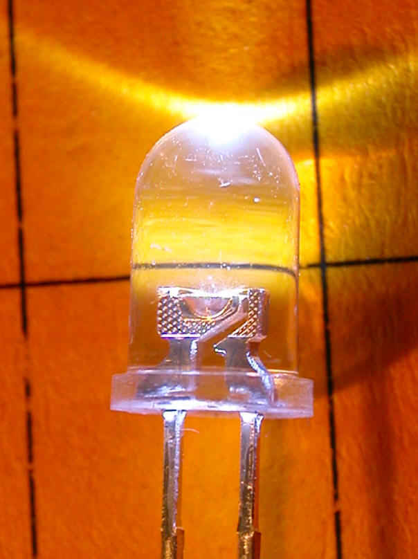
Here a 5 mm LED is connected to power. You can see light emitting from the top of the LED's lens as well as a bright spot in the center of the reflector deep within the LED. You can also see that there more plastic to the left and right that might be removed.
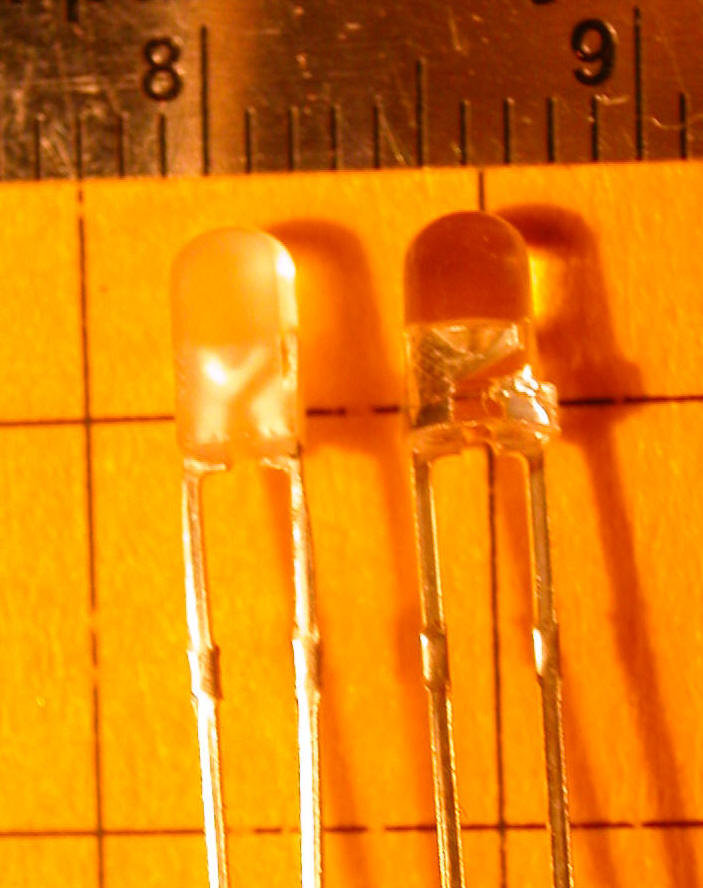
In this view the 3 mm LED has been rotated 90 degrees. We can see that there is a good bit of plastic on each side of the reflector that can be safely removed to reduce its size.
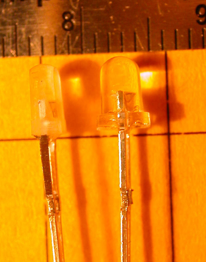
Here a smaller amount has been removed from the area to the sides of the anode and cathode.
In this photo 7 unmodified 3 mm LEDs are in the lower left. In the upper right are the same 7 LEDs but after they have been ground down with an abrasive wheel on a Dremel. The dimension from left to right has not been reduced much but the dimension from top to bottom is much smaller. It is possible to remove too much material and destroy the LED. Test the LEDs often during grinding or grind them with power applied (through a current limiting resistor) so that you can learn when they fail!
SOFTWARE
I won't go into as much detail on the intricacies of the software as I normally do since the programming software that I use with the PIC chips (as opposed to that used with the PICAXE) is quite expensive and not likely to be on too many of your shopping lists! I will say, however, that the programming routines that I have developed do the following:
Perform PWM functions on any two of the 4 or 7 LEDs so that one LED brightens as the one before it in sequence dims. This gradual change in brightness gives a much more appealing look during "movement" of the light.
Watch the setting of the potentiometer so that the speed of the progression through a given sequence can be speeded up or slowed down. Note that the microcontroller only looks at the potentiometer setting once per run through the set of LEDs. This means that it may take a few seconds to have a change in the pot's setting take effect if you are running at a very low speed.
Watch the first jumper that is installed on the six pin header. This jumper determines if the unit will work with 4 or 7 LEDs. If the jumper is off it works with 7. If it is on it works with 4.
Watch the second and third jumpers on the header. These two jumpers can be arranged in any of 4 patterns: both off, both on, first one on and second one off & first off and second one on. These jumpers are used to select which of the 4 patterns that will be used with the LEDs. Note that the patterns for the 4 LED arrays are completely different and separate from those for the 7 LED arrays. As with the potentiometer, jumper changes are only noted once per a run through a pattern.
SEVEN LED ARRAY SEQUENCES
As mentioned above the 7 LED array, shown below, has a default pattern that lights the LEDs in this pattern:
1, 2, 3, 4, 5, 6, 3, 7, 1, ...
This gives the most traditional horizontal "8" pattern. This pattern is selected with no jumpers are place at position j2 or j3.
The second sequence is selected by installing a jumper on J2. It uses this order: 1, 3, 5, 6, 2, 1, 3, 5, 4, 7, 1, ... When viewed from a distance of a few feet this sequence gives a similar but still significantly different effect.
The third sequence, selected by removing the jumper from "j2" and placing it on "j3" tries something different. It follows the first sequence but it flashes the LEDs on and off without using PWM. This gives a more distinct and somewhat choppy display at low speeds but a very appealing pattern at the highest speeds.
The fourth sequence repeats the second pattern without using PWM. Again, it is most appealing at high speed.
FOUR LED ARRAY SEQUENCES
If a jumper is installed on the pins on the left side of the header, labeled "j1", the unit will work with 4 LEDs.
The default sequence, with no jumpers on "j2" and "j3" gives this pattern:
1, 2, 4, 3, FLASH 1 & 3, 2, 4, 1, FLASH 1 & 3, ... This pattern uses a simplified, 4 LED figure "8" pattern with a difference. After each 1/2 of the sequence the two horizontally aligned LEDs, 1 and 3, flash for 1/4 second. This is the closest thing I could come up with to the full horizontal "8" that you can get with 7 LEDs.
Installing a jumper on "j2" gives:
1, 2, 3, 4, 1, 4, 3, 2, 1 ... This is a basic back and forth pattern.
Placing a jumper on "j3" gives a simple clockwise rotating sequence: 1, 2, 3, 4, 1, 2, 3, 4, ...
Installing jumpers on both "j2" and "j3" rocks back and forth illuminating: 1, 2, 3, 2, 1, 4, 3, 4, 1, ...
If you have any ideas on other sequences of LEDs or places to flash or extinguish one or another I would be glad to custom program chips to give them a try.
ENGINE INSTALLATION
Once I had a working prototype of the circuit and the software was completed I looked around for a diesel engine that I might use for a test installation. The only diesel engine in my collection that might have used Mars lights is an AristoCraft FA1. I removed the factory installed headlight and found that the remaining hole was well over the size that I needed to install a set of seven 3 mm LEDs.
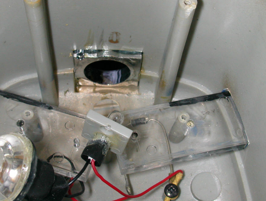
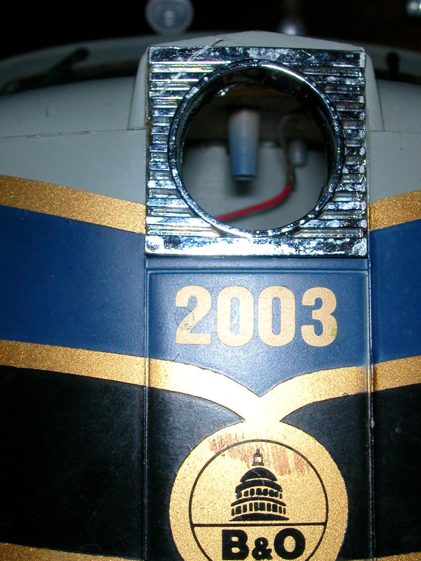
In the temporary installation shown in the photo below I added a paper spacer inside of the opening and still had plenty of room for the 3 mm LEDs
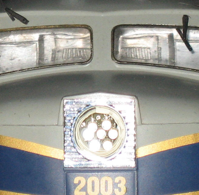
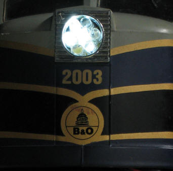
On closer examination I found that the opening was large enough to just barely accommodate a set of seven 5 mm LEDs as shown below.
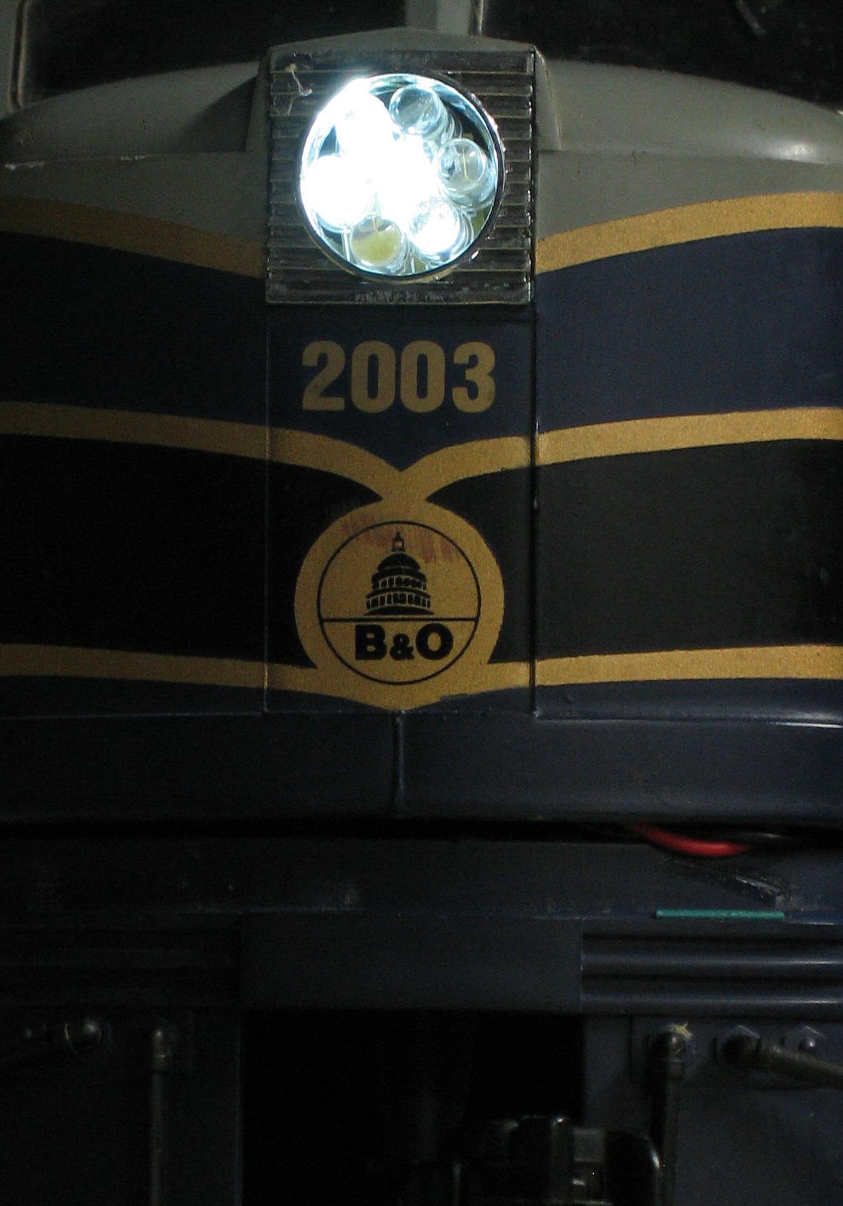
This is a project that certainly requires some video to properly illustrate what the circuit can do. The first set of videos were taken on my indoor layout with LEDs installed in the AristoCraft FA1 that is pictured above.
Video 1 is of the FA1 with only four 3 mm LEDs.
Right click the box below and select "play"
Video 2 shows the same engine with seven 3 mm LEDs
Right click the box below and select "play"
Video 3 has seven of the brighter 5 mm LED installed.
Right click the box below and select "play"
The last two videos are of the same engine with seven 5 mm LEDs. It is being run on my outdoor railway for a distance of about 50 feet.
Video 4 shows the engine being run at dusk. The engine is first seen as it leaves a tunnel. The Mars light can be clearly seen in the distance. It is occasionally eclipsed as it passes behind plants and buildings as it nears the camera
Video 5 follows the same route with the same light and engine but the video is from a bit later in the evening when it is almost completely dark. Other lights that can be seen are from my lighthouse (in the bog of our pond) and from the photo studio that is in one of the buildings (someone must be using a flash!)
ORDERING
I have a limited number of the circuit boards on hand and would be glad to provide them to interested LSOL members. Please send orders to dave@davebodnar.com . The prices are as follows:
Circuit boards (main board and LED board) - $12.00 (I wish this could be less but in prototype quantities circuit boards are expensive!)
Programmed PIC processor - $7.00
Complete kit of parts (both boards, programmed PIC, voltage regulator, 7 white LEDs (3 mm or 5 mm), resistors, jumpers, etc - the only thing you add is power and hook up wire to connect the two boards) - $26.00
Complete unit, wired and tested, with 7 LEDs or 4 LEDs mounted as shown above - $45.00
You supply power to the unit either from batteries (7 - 24 volts DC) or from any other reasonably clean source of DC power. This can be from the power available on the circuit boards of many modern engines. If power is taken directly from the track it must be run through a bridge rectifier and filter capacitor. See 5 Volt Power for Railway Electronic for details.
|
New Circuit Board
- Revised Jumper Sequences The new board does not currently support the 4 LED sequences due to a lack of user demand. In stead there are four seven LED sequences that are accessed as described below. Not that the center jumper is NOT used at all with this design and the latest software. Only put jumpers on jumper 1 and jumper 3 to change effects SEVEN LED ARRAY SEQUENCES If no jumpers are installed the lights are illuminated in this sequence 1, 2, 3, 4, 5, 6, 3, 7, 1, ... This gives the most traditional horizontal "8" pattern. This pattern is selected with no jumpers are place at position j1 or j3. The LEDs are brightened and dimmed using PWM so that they illuminate and dim slowly.
The second sequence is selected by installing a jumper on J1 only. It uses this order: 1, 3, 5, 6, 2, 1, 3, 5, 4, 7, 1, ... When viewed from a distance of a few feet this sequence gives a similar but still significantly different effect. The third sequence, selected by removing the jumper from "j1" and placing it on "j3" tries something different. It follows the first sequence but it flashes the LEDs on and off without using PWM. This gives a more distinct and somewhat choppy display at low speeds but a very appealing pattern at the highest speeds. The fourth sequence is selected by installing a jumper on J1 and J3. This mode repeats the second pattern without using PWM. Again, it is most appealing at high speed.
|
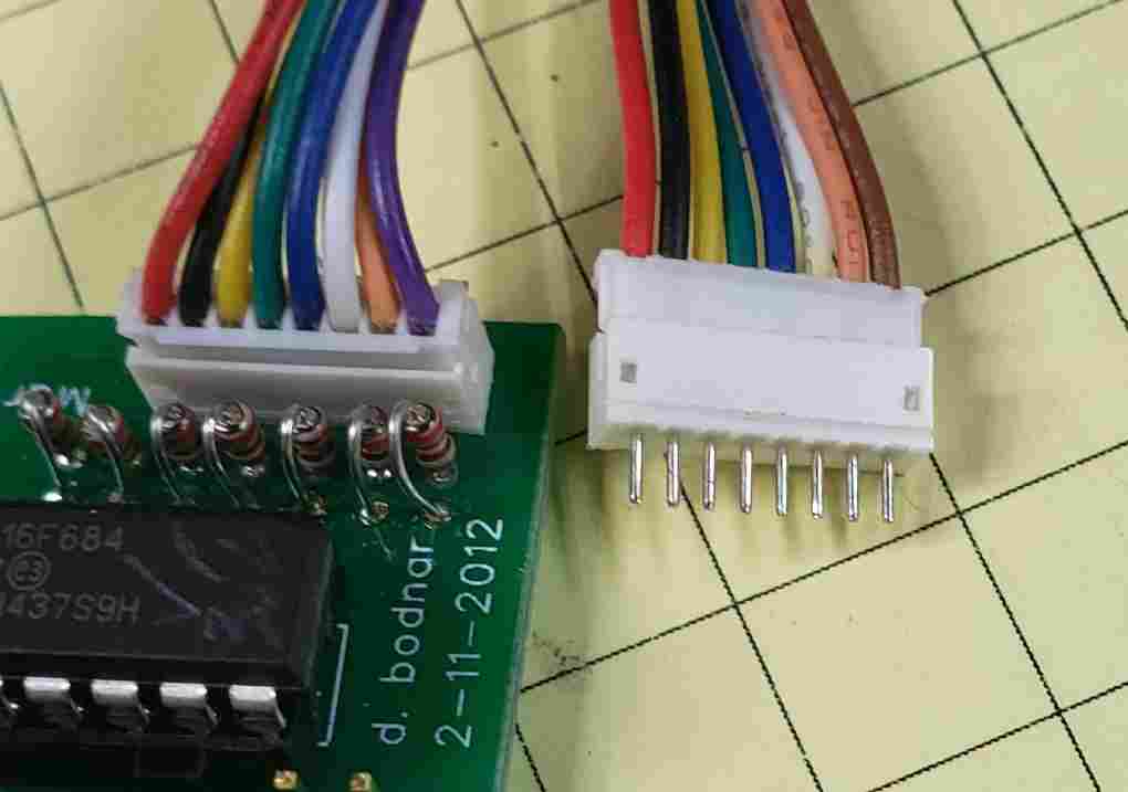
| New Circuit Board - Building the Kit The new circuit board and the parts to complete the kit are shown below.
|
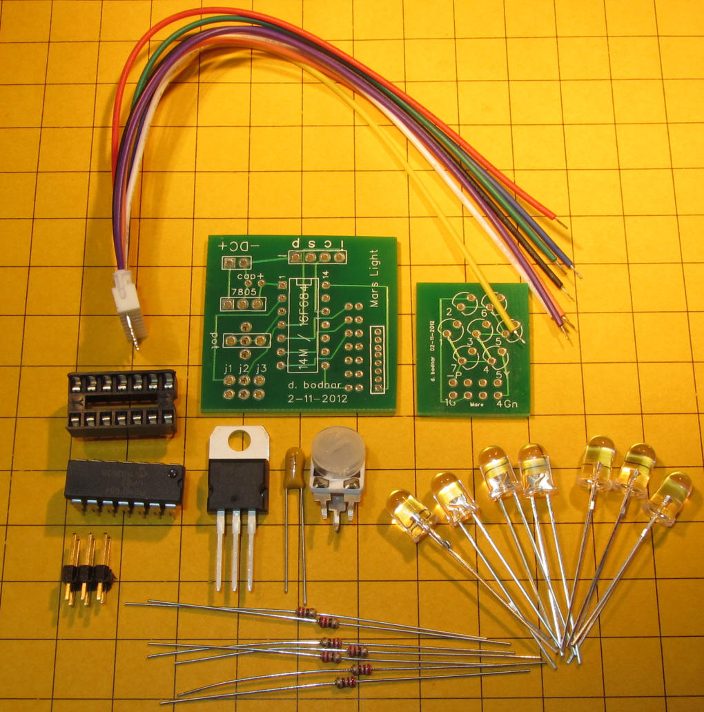 PLEASE NOTE: The latest shipment of these cables substituted brown for purple --- see photo below with old on left and new on right - please solder brown where purbpe is shown
|
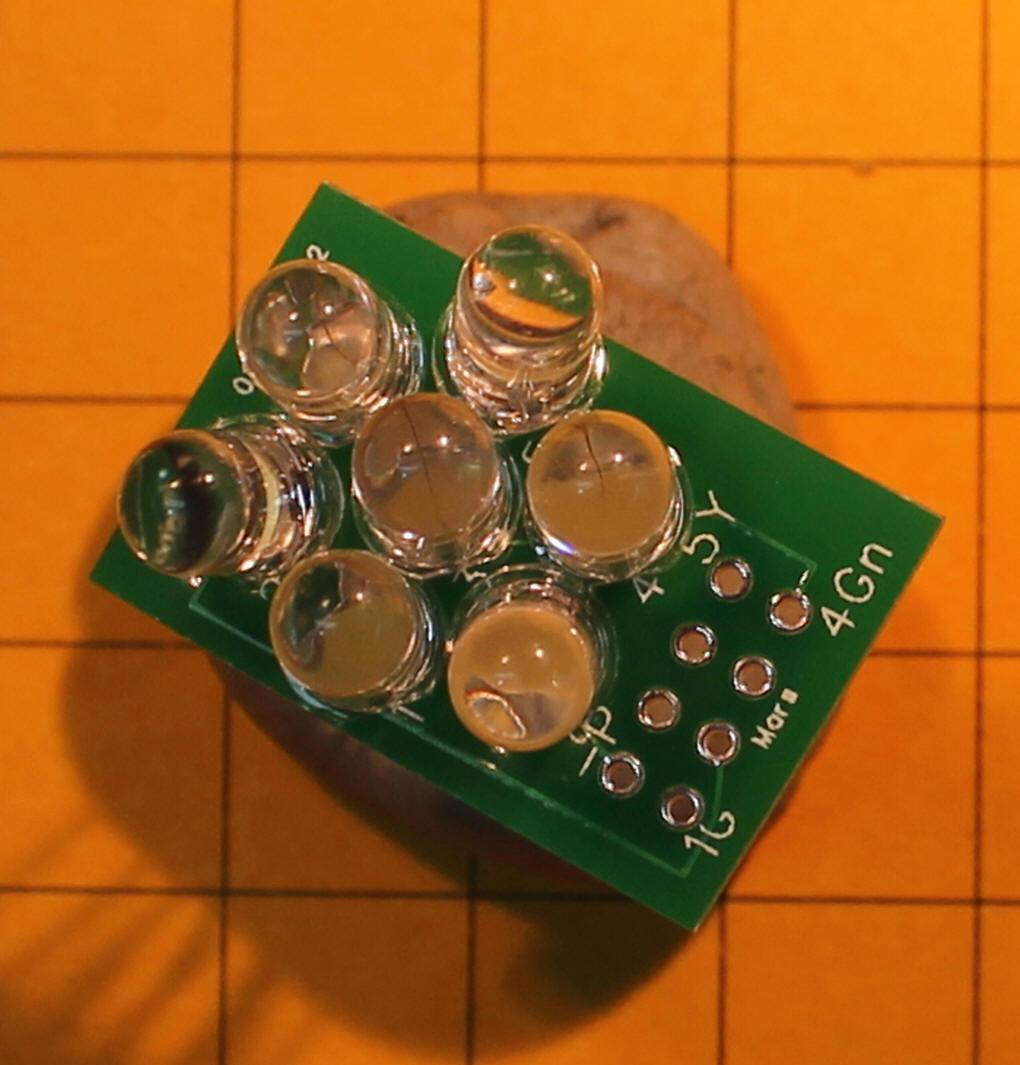
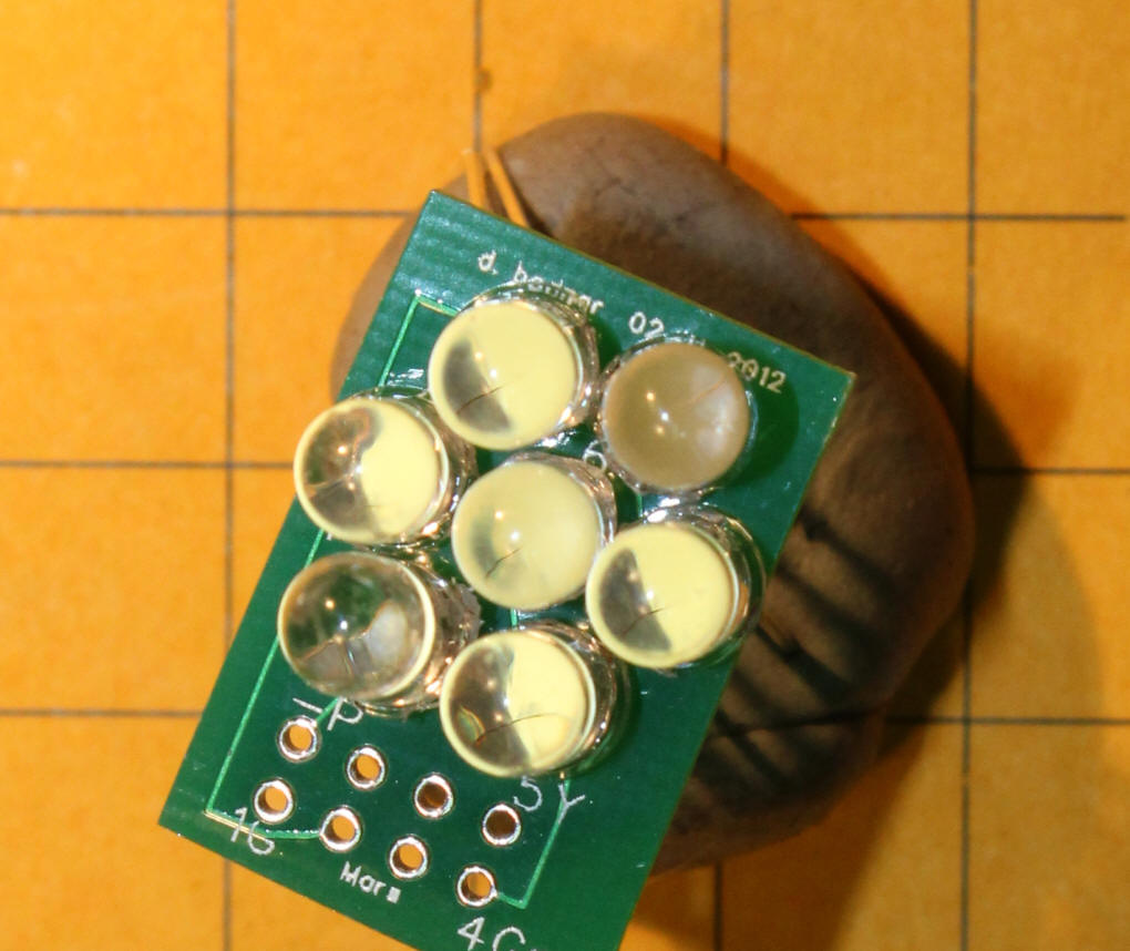
| When mounting 5mm LEDs you will note that the
flanges at the base of the LEDs bump into each other and preventing the
LEDs from sitting flat on the circuit board.
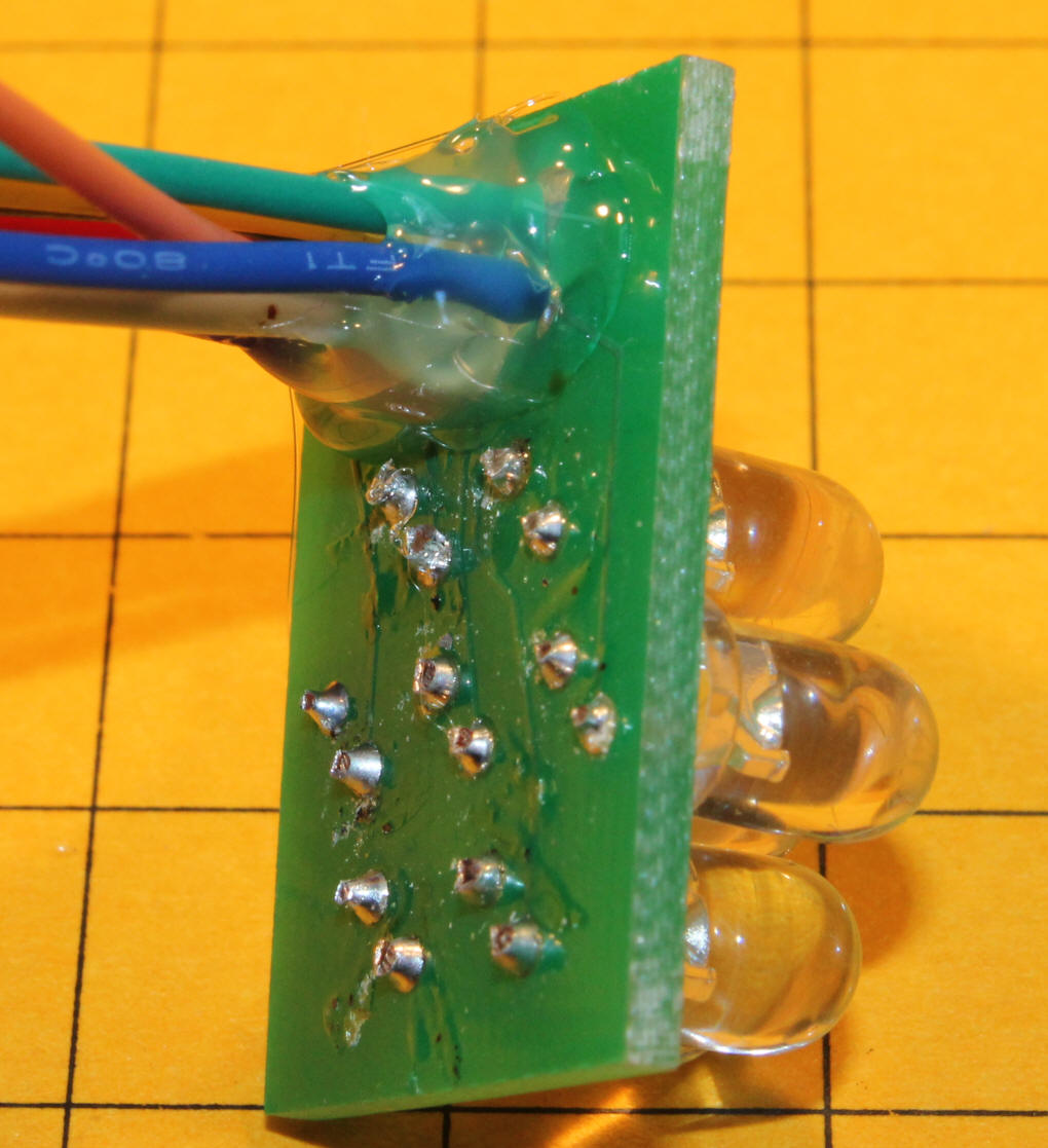
Removing the flanges, by nipping, filing, or sanding, allows them LEDs to fit onto the board as shown here. Make sure that the LEDs are inserted with the right orientation. The longer lead is positive (the Anode) and goes into the hole away from the flat spot in the drawing.
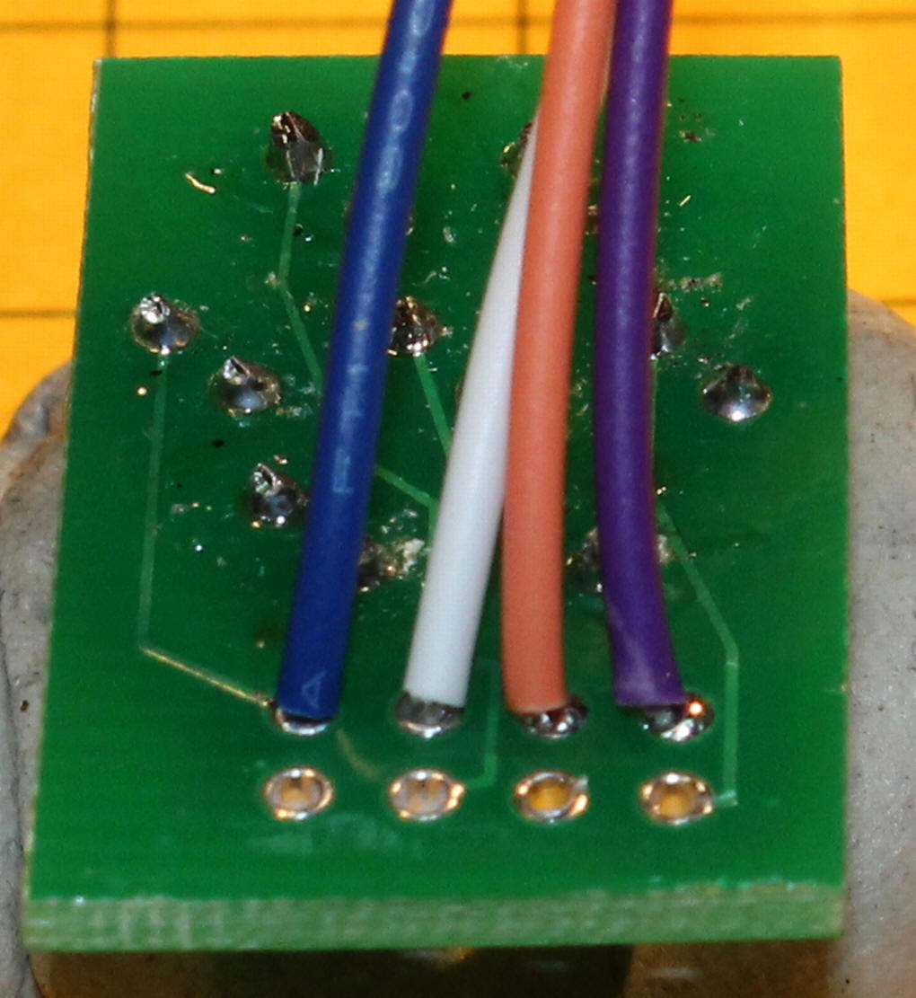
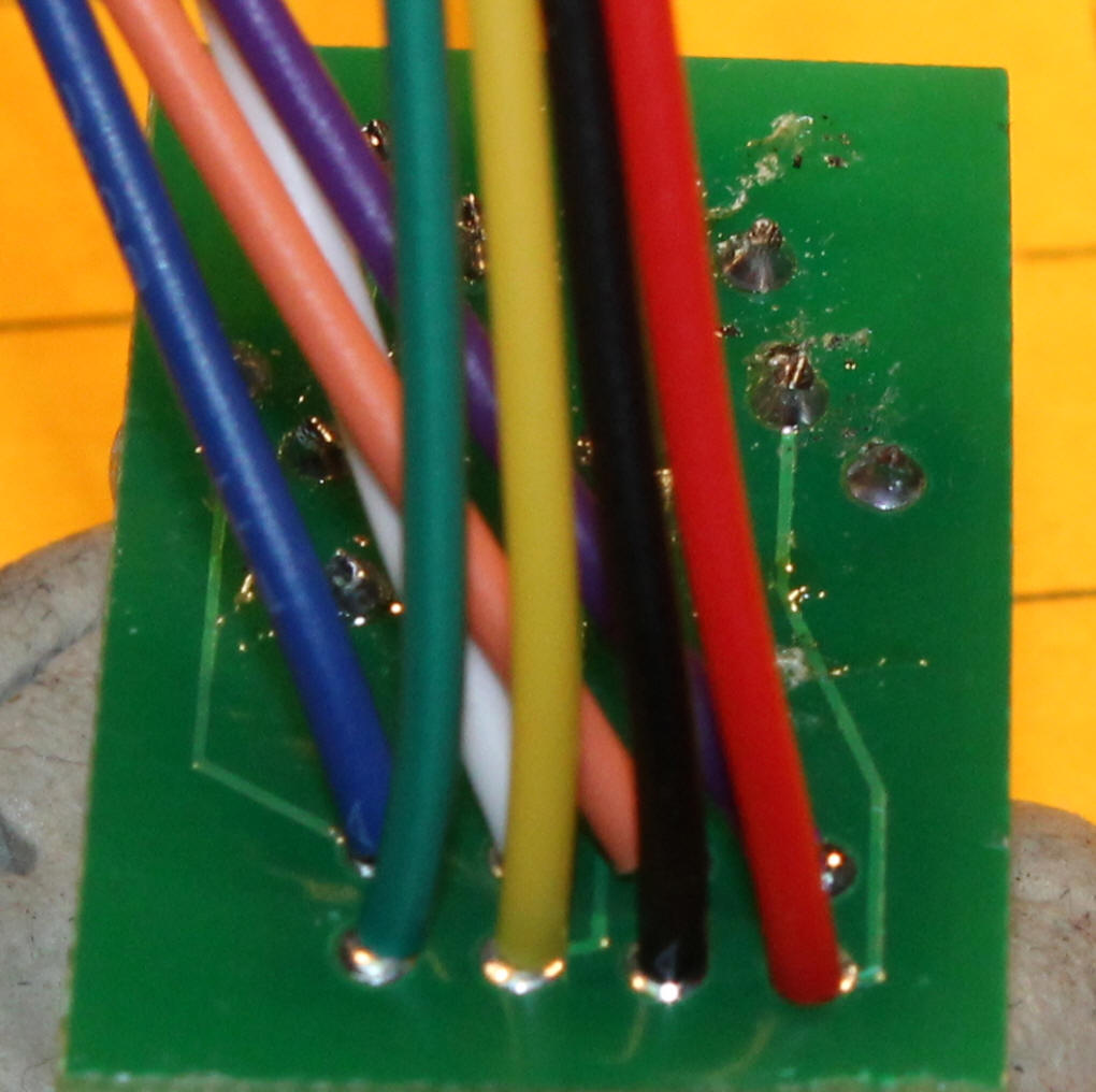
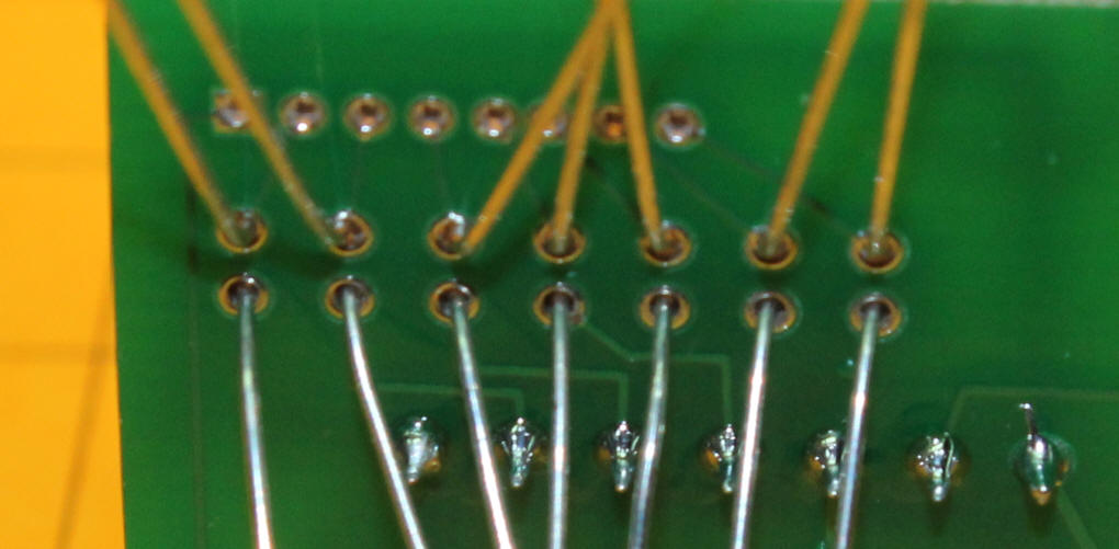
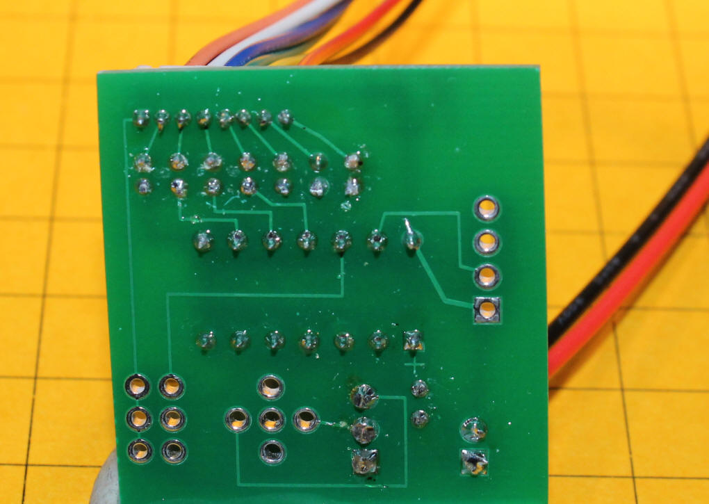
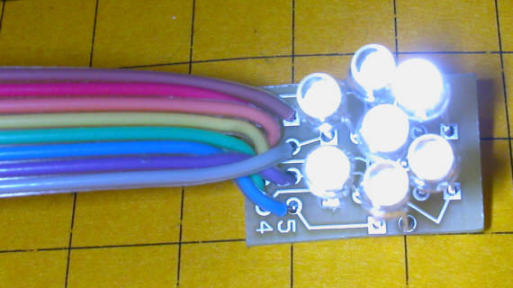
The wiring harness for the LED board is soldered as shown here. Solder the purple, white, orange and blue wires first. Make sure that they go into the holes as in the photo. REMEMBER: your cable is likely to have a brown wire where this photo shows purple! Next solder the green, yellow, black and red wires.
The thin wires are quite fragile. Adding a bead of hot melt glue around them will prevent them from breaking away from the board.
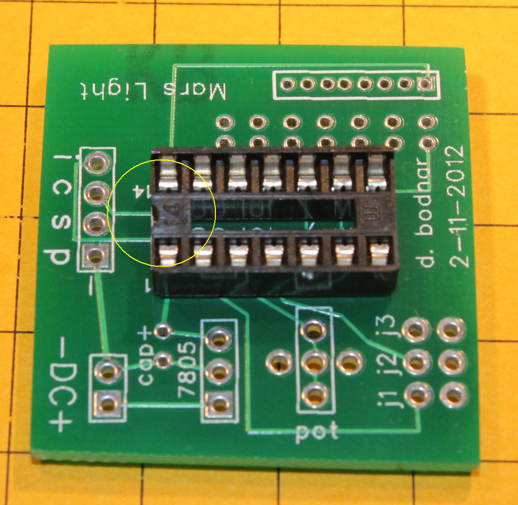
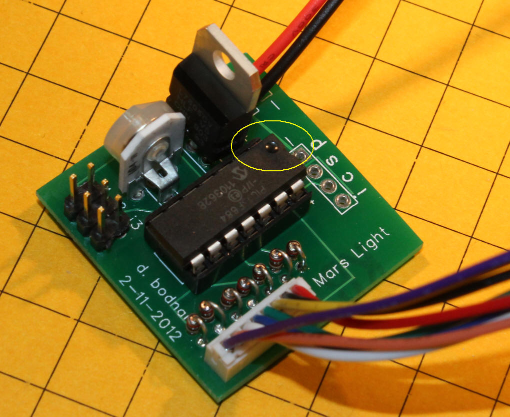
Insert the 14 pin socket into the main board with the notch oriented as shown (note the yellow circle). Solder from the back.
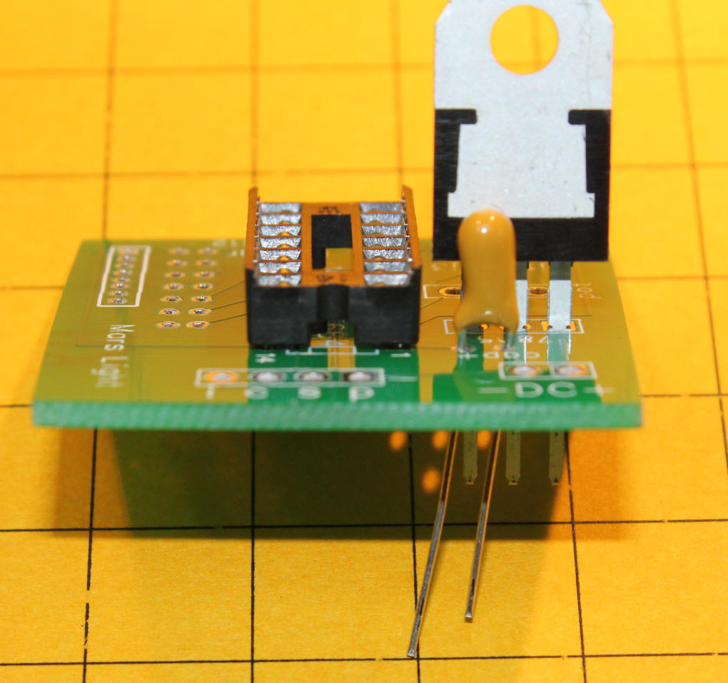
Insert the 7805 regulator and tantalum capacitor as shown. The label on the capacitor faces the 7805. The longer lead on the cap is to the left.
After soldering the regulator and capacitor and trimming their leads apply power to the + and - terminals and test pins 1 and 14 with a volt meter. The meter should show 5 volts, plus or minus a 1/10 volt.
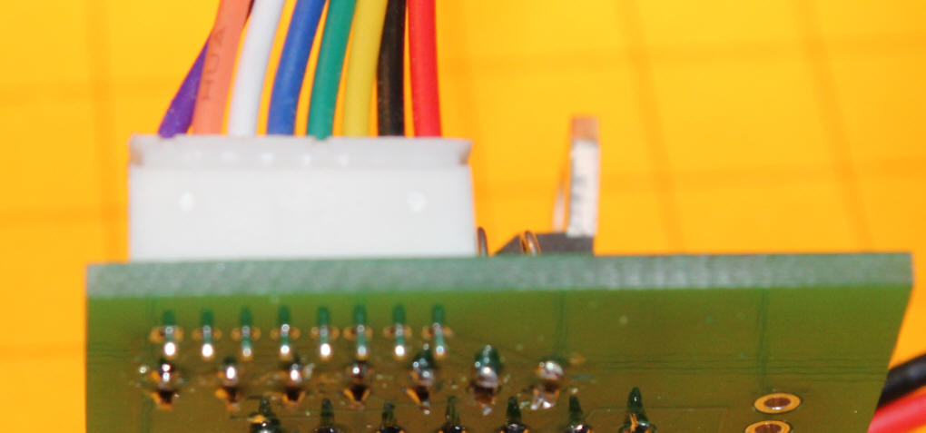
Insert the seven 220 ohm resistors and bend their leads as show to facilitate soldering.
The leads are close together. Bending them makes soldering easier.
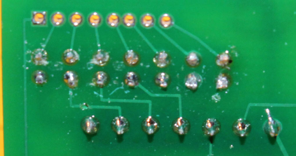
After soldering trim the leads and make sure there are no solder bridges between connections.
Insert the socket with the red wire closest to the center of the board and solder.
These pins are very closer together and can easily be bridged. Check & double check for errors.
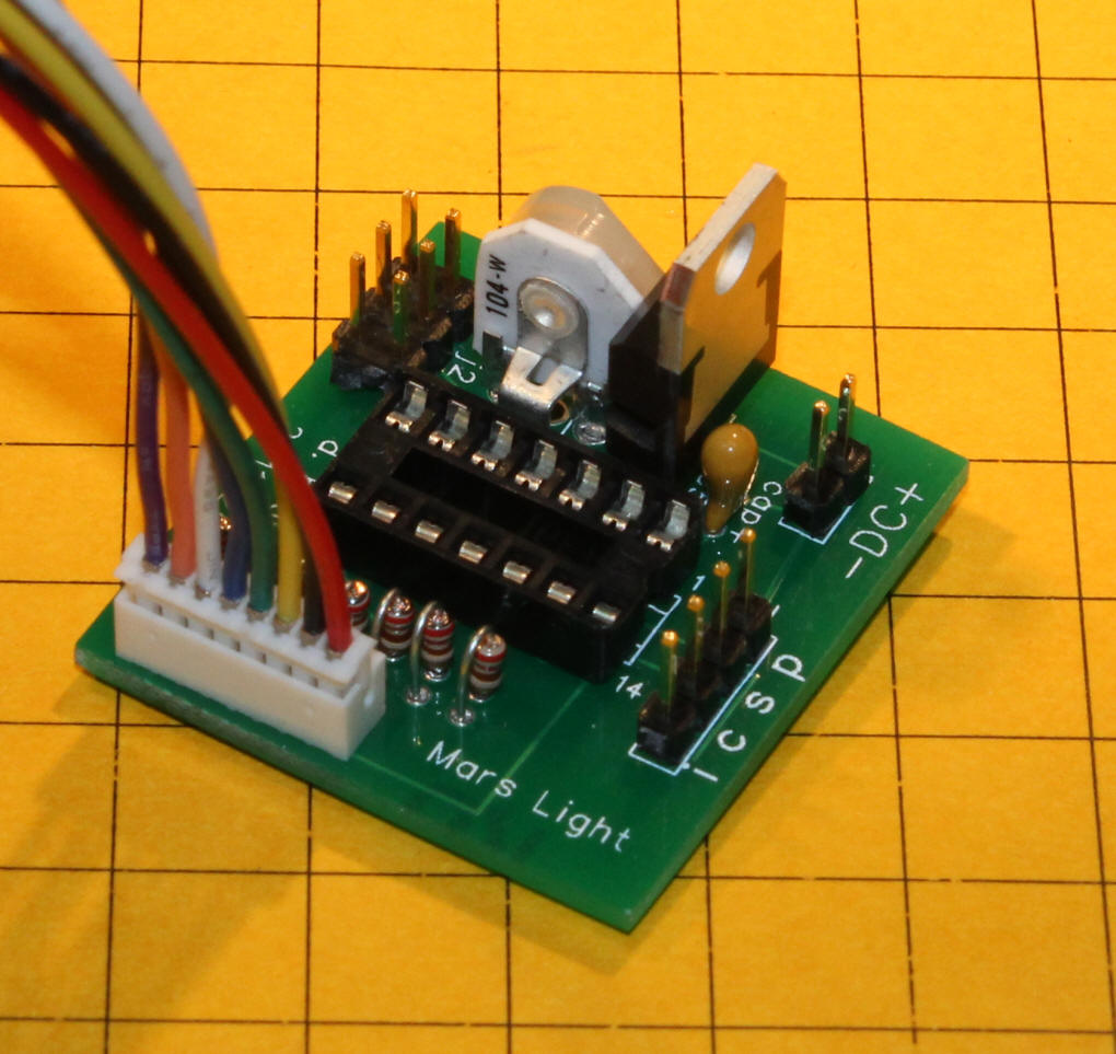
Insert and solder the 6 pin jumper block and the speed adjustment potentiometer as shown. Note that this sample board shows the ICSP pins. These are only used for programming and testing and are not normally included.
Insert the PIC chip with its notch or pin 1 indicator over the notch in the socket.
|