Hardware
The transmitter that I am using is from
HobbyKing.
It is the
FrSky V8HT 2.4Ghz DIY Module
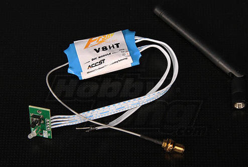
Note that the transmitter is
billed as DIY since there are no controls, only an input for PPM
data.
Any number of receivers should work.
I chose an 8 channel unit,
the V8FR

One thing that I found confusing is that
the receiver has no plug for a battery connection. There are
only two antennas coming from one side and eight 3 pin connectors on
the other that go to the eight servos. I finally figured out
that you need to use one of the servo plugs to supply power.
It would have been nice to see something about doing so in the
documentation.
The RF chip in the receiver is from TI -
data here:
http://www.ti.com/lit/ds/swrs040c/swrs040c.pdf
Connections
The receiver was connected to 5 volts DC through one of the
servo plugs. The transmitter was connected to 7.4 volts DC.
Its PPM connection went to pin 12 on the PICAXE. The
transmitter's ground was also connected to the ground on the PICAXE
board.
The transmitter and receiver were linked
following the directions that came with the tramsmitter. |
Software
I did some research and found a number of sites on the Internet
that helped in getting the transmitter hooked up to a PICAXE
microcontroller.The one that worked
best was found here:
http://www.picaxeforum.co.uk/showthread.php?16665-Picaxe-to-PPM-for-picaxe-control-of-RC-plane
The program on that page that I modified
for my first experiments is titled "Working PPM-pulse train" from
Peter Graat. Thanks, Peter!
The program was written for a PICAXE 20X2,
a chip that I did not have on hand. I did have the newer 20M2
chip. Unfortunately the 20M2 does not support 64 MHz operation
as does the 20X2 so I had to spend some time adjusting the variables
& constants in the program to get a proper set of PPM pulses.
The goal was to generate pulses like the
ones described here:
http://www.mftech.de/ppm_en.htm
Here is an image from that page:
Each frame is 22.5 ms long and is composed
of a Start pulse followed by 8 data pulses, each preceded by a 0.3
ms pulse. The Start pulse must be adjusted to give 22.5 ms for
the total frame.
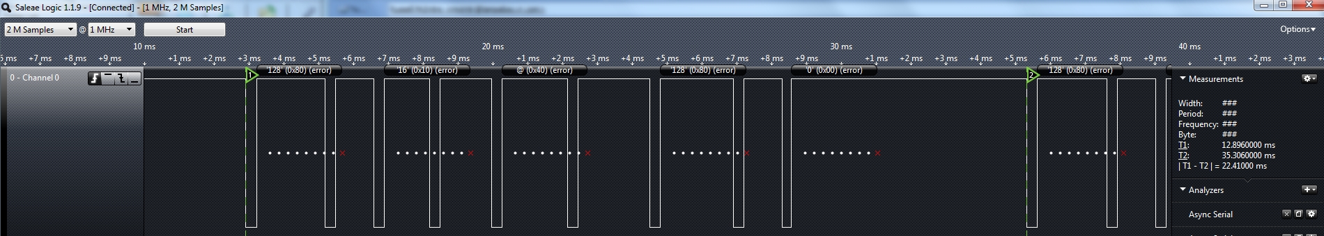
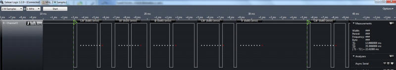
The modified program that I used generates
a proper frame as seen here. (Click on the image to see a
larger version.)
'd. bodnar 1-15-2012
revised for 20M2 PICAXE
'had to revise variables for 32 mhz operation
'working well!
'from http://www.picaxeforum.co.uk/showthread.php?16665-Picaxe-to-PPM-for-picaxe-control-of-RC-plane
'Version 1 13-5-2011 Peter Graat
'
'HARDWARE DEFINITIONS PICAXE 20X2 on 64 MHz
'
'First idea from RickHarris with additions from Hippy of
PICAXE-forum
'
'
'generate PPM-pulse train for 8 channels between 1ms and 2ms
'400 micro sec inter channel break
'8 channels - 0 to 5v input to ADC.
'frame rate stable 22.5ms
'
' PICAXE 20X2
' --------------
' +5 Volt -|1 \/ 20|- 0 Volt
' Serial in -|2 19|- Serial out
' channel 3 -|3 C.7 B.0 18|- channel 1
' -|4 B.1 17|- channel 2
' -|5 B.2 16|- channel 4
' -|6 B.3 15|- channel 5
' channel 7 -|7 C.3 B.4 14|- channel 6
' channel 8 -|8 C.2 B.5 13|-
' -|9 B.6 12|- PPM-pulse train
' -|10 B.7 11|- Dummy
' --------------
'
'
'variables like: correction, sync, rust, pauze, mult and div are
'iterations after carefully studying oscilloscope-pictures
'
#PICAXE 20M2
''#NO_TABLE
OUTPUT B.6,B.7 'define outputs
INPUT B.0,B.1,C.7,B.2,B.3,B.4,C.3,C.2 'define input
'VARIABLE DEFINITIONS
SYMBOL ch1 = w0 'channel 1
SYMBOL ch2 = w1
SYMBOL ch3 = w2
SYMBOL ch4 = w3
SYMBOL ch5 = W4
SYMBOL ch6 = W5
SYMBOL ch7 = W6
SYMBOL ch8 = W7
SYMBOL correction = w8
SYMBOL sync = w9
SYMBOL rust = w10
SYMBOL pauze = w11
SYMBOL mult = b24
SYMBOL div = b25
'CONSTANT DEFINITE
'PIN-DECLARATION
SYMBOL PPM = B.6
SYMBOL DUMMY = B.7
'INITIALIZATION
init:
SETFREQ m32
LET ADCSETUP = %0000000111111110
sync = 96' 96 gives .30
correction = 874
mult = 25'mult & div to correct ADC to msec
div = 32'
LOW PPM
HIGH DUMMY
w13=0
main:
'READADC10 B.0, ch1 '1msec = 0 = 0 Volt and 2mec = 1024 = 5 Volt
w13=w13+10 'used to move the #1 servo arm back & forth
ch1=w13
if w13>1000 then
w13=0
endif
ch1=ch1*mult/div
ch1=ch1+correction
'READADC10 B.1, ch2
ch2=ch2+60
if ch2>900 then
ch2=0
endif
ch2=ch2*mult/div
ch2=ch2+correction
READADC10 C.7, ch3
ch3=200
ch3=ch3*mult/div
ch3=ch3+correction
READADC10 B.2, ch4
ch4=400
ch4=ch4*mult/div
ch4=ch4+correction
READADC10 B.3, ch5
ch5=800
ch5=ch5*mult/div
ch5=ch5+correction
READADC10 B.4, ch6
ch6=1000
ch6=ch6*mult/div
ch6=ch6+correction
READADC10 C.3, ch7
ch7=1023
ch7=ch7*mult/div
ch7=ch7+correction
READADC10 C.2, ch8
ch8=0
ch8=ch8*mult/div
ch8=ch8+correction
rust = ch1+ch2+ch3+ch4+ch5+ch6+ch7+ch8
rust = rust/2
pauze = 6700-rust''13400-rust
'send pulse stream out
LOW PPM
PULSOUT DUMMY,sync : PULSOUT PPM,ch1
PULSOUT DUMMY,sync : PULSOUT PPM,ch2
PULSOUT DUMMY,sync : PULSOUT PPM,ch3
PULSOUT DUMMY,sync : PULSOUT PPM,ch4
PULSOUT DUMMY,sync : PULSOUT PPM,ch5
PULSOUT DUMMY,sync : PULSOUT PPM,ch6
PULSOUT DUMMY,sync : PULSOUT PPM,ch7
PULSOUT DUMMY,sync : PULSOUT PPM,ch8
PULSOUT DUMMY,sync : HIGH PPM
PAUSEUS pauze
goto main |