| Overview: A reversing loop is frequently used by model railroaders to reverse an engine's path on a single main line. The problem with reversing loops is that they create a short circuit within the track as the loop connects the two rails of the main line. This problem is addressed in a number of ways. The simplest and most common is to completely isolate a section of the reversing loop from the main line. This isolated section must be long enough to accommodate the engine and any cars that might have pickup wheels that feed power to the engine. The isolated section is powered from the main line through a bridge rectifier. This device supplies the same polarity of power regardless of the polarity that is fed into it. When the train has fully entered the reversing loop a reed switch is tripped by a magnet under the engine triggering the controller which throws the DPDT relay reversing the power to the main line so that the train moves in the proper direction upon exiting the reversing loop.
|
| Test Layout:
|
| Schematic: The schematic shows that the controller is based on a PIC 16F88 processor. Two, identical units are used - one for the left side of the layout and one for the right. The Bridge Rectifier is not on the same circuit board as the other components as it is simpler to place it near the start of the reversing loop.
The track in the crossing siding area is wired as below. The two blocks are completely isolated from the main line except for the two diodes that connect one end of each block to the main line.
|
| Program Operation: Both engines start somewhere on the mainline other than an isolated section. When an engine crosses a sensor on an isolated block in the reversing loop it triggers a DPDT relay and voltage is reversed. The bridge rectifier keeps the engine moving forward until it clears the block. When an engine enters its crossing siding it stops when it crosses the open gap in the track. It also triggers its crossing block sensor. When the circuit finds that both engines have returned to the crossing blocks the polarity of both relays is reversed and the engines continue on their way through the diodes at the other end of the crossing block. Note that the system does not automatically accelerate or decelerate the engines when starting or stopping - this will be added in the next revision, I hope!
|
|
Video: Click here for a short video in WMV format - may take a few minutes to download and play Click here for the same video in MPG format - may take a few minutes to download and play
|
|
Update - Thursday, June 28, 2007 A good bit of experimentation over the last two days has resulted in a reverse loop controller and software that is improved in a number of ways.
|
| Schematic: Note that the controller is actually made up of two PIC16F88 processors, two relays, etc. The Mosfet (Q1) is used to control the acceleration and deceleration of the trains. It is most important that proper polarity be observed when supplying power to the circuit from the "Train Power Supply" - A meter must be used to determine + and - terminals and if the unit that is used has a Forward / Reverse switch it must be disabled or covered to prevent its being used. The track sections at the bottom of the schematic show the diode placement in the crossing siding.
|
|
Video Update: Click here for a short video in WMV format - may take a few minutes to download and play Click here for the same video in MPG format - may take a few minutes to download and play |
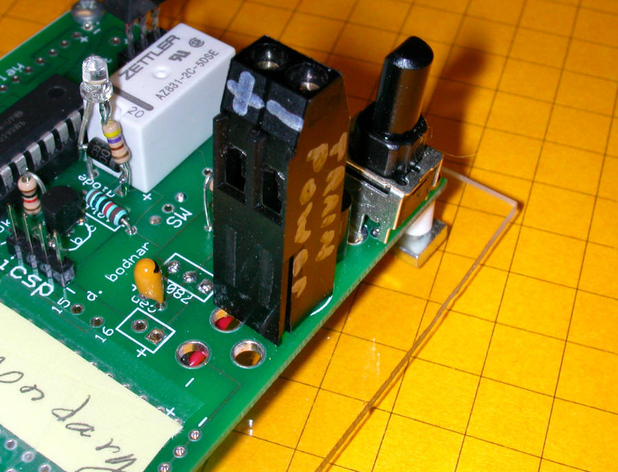
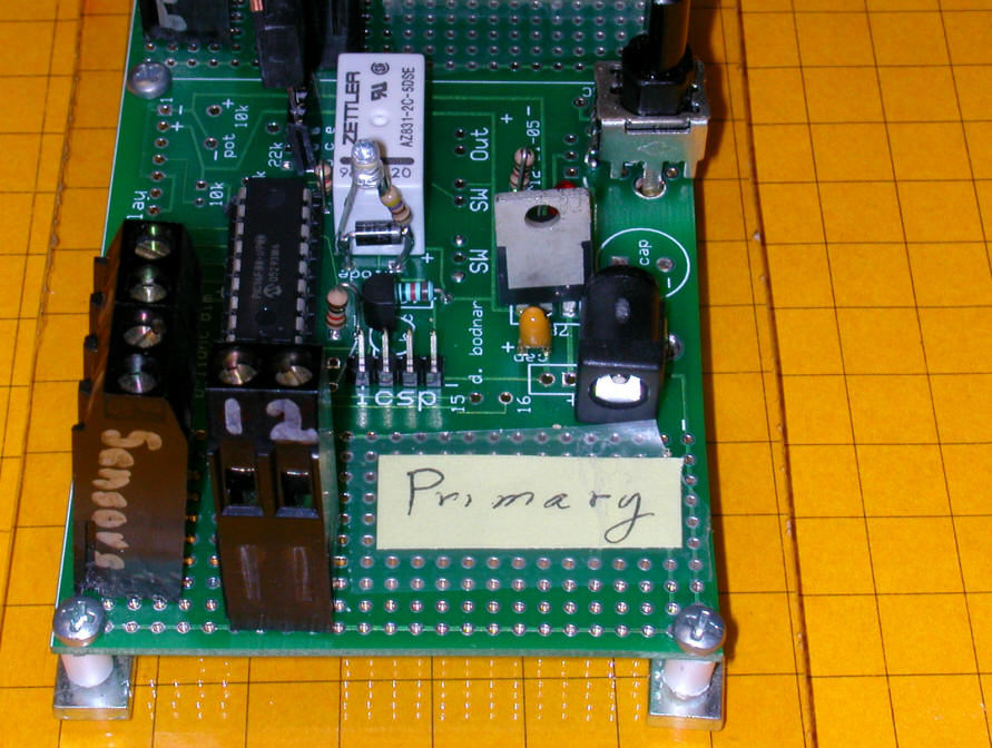
| Controller: The prototype controller is shown below - two identical PIC microcontrollers, relays, Mosfets, etc. The reed relays connect just below the white boxes (relays). Note that the reed relays must be connected by twisted pair cable.
|
| Diodes: Here is the matrix of diodes (no an breadboard, no less) that are used to control the crossing sidings.
|
|
Update - Monday, June 2, 2007 After a good bit of experimentation and testing some observations :
|
|
Update - Tuesday, July 3 --> Thursday, July 5, 2007 Glitches that appeared to be completely random seem to be due primarily to the use of one section of non-twisted pair wire to connect a reed switch to the controller. When that was replaced the problems almost completely disappeared. The only other observation is that all track connections must be 100% solid - soldered or tightly attached with screws or rail clamps. While on the trail to discovering the above I doubled up the loop reed switch sensors. Two identical reed switches were soldered together side-by-side so that the chance of a missed magnet were lessened dramatically. I am not sure if that made much difference but it is inexpensive insurance. Later in the day... The occasional glitches kept creeping in but may have been stomped upon with a software change. I added a counter to each reed switch hit - the software now ignores single or even double hits of the reed switches - only after 3 or more hits are detected is a valid hit recorded and acted upon. The multiple hits are not a problem for two reasons. First of all the PIC processors are very fast and typically record 4 or more hits per pass. In addition a second magnet was added to each engine. I now get as many as 9 hits recorded on each reed switch each time an engine passes. (note: by hit, I mean consecutive time periods of several milliseconds where the reed switch is held closed - these are NOT open/close/open cycles) Thursday Another hardware change was made even though it may not have been needed. The "pull down" resistors that had been used to hold the input pins on the PIC processor low until the reed switch was crossed momentarily pulling them high were changed from 10K to 1K. The lower resistor value should make it harder for unintended pulses to cause false readings. In addition a small (.1 mfd) capacitor was placed between each sensor pin and ground, again in hopes of filtering out noise. The system ran flawlessly for a number of hours on Wednesday completing 832 "laps". It continues to run equally well today with the resistor and capacitor changes. Later in the day... A request for a random delay within the reverse loop was made. The software was modified so that each engine would come to a stop within a foot or so of the reed switch in the reverse loop. Once stopped each engine pauses for a random period no less than 3 seconds and no more than 15 seconds. Although not yet implemented, the maximum time will be adjustable by means of a potentiometer. Note that the time in the crossing sidings is fixed and that one engine always exits a few seconds before the other. A video is below: Click here for a short video in WMV format - may take a few minutes to download and play Click here for the same video in MPG format - may take a few minutes to download and play
|
Unit as Shipped
|
Track Setup
|
Controller Setup
|
Operation
|

|
 |
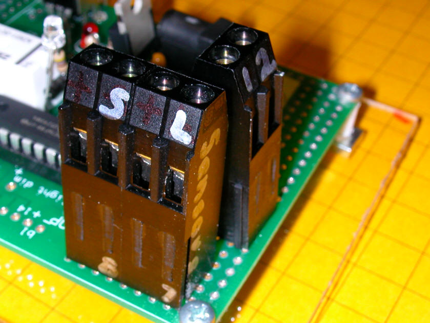
Board Connections
In this close up you can see the four terminals -
|
|
Software Version 4.1
' D. Bodnar 7-6-2007 |