Controlling Reverse Loops & Wyes
Dual Coil Relays to the Rescue!
revised 06-16-08
| Warning: This article does NOT contain information
about hi-tech electronics! It does not rely on microcontrollers, transistors or even lowly resistors. Just relays, reed switches and a few diodes, most of which are optional. I know that may disappoint some readers but it just had to be done! |
Model railroaders have used relays to control various devices on their layouts for years. In this article I would like to review how relays operate and explore an unusual type of relay that has some interesting capabilities. This single inexpensive device will allow you to automatically navigate a wye or a reverse loop with minimal effort.
Relay Overview
Traditional relays open or close a set of contacts when power is applied to a coil. The illustration below shows a basic SPDT (single pole double throw) relay. When pushbutton switch SW is pressed power flows from the battery to the relay's coil turning it into an electromagnet. The contacts move within the relay and the NC (normally closed) contacts open and the NO (normally open) contacts close. When SW is released power is removed from the coil, it loses its magnetic field and a spring returns the contacts to their original position. Whatever is connected to the contacts is turned on or off by pressing the button.
A relay with two sets of contacts is called a DPDT (double pole double throw) relay. Its contacts can be used to reverse the polarity of the DC power that is connected to a model railroad's track. When the relay is activated the direction of the train reverses. The two connections from the power supply go to the two common contacts on the relay. The NC connection from one set of contacts is connected to the NO on the other and the reverse is done with the other set. If you follow the way the wires connect through the relay contacts you can see how the polarity is reversed when the relay is activated.
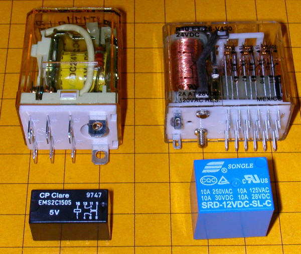
This photo shows several different types of single coil relays. The coil and contacts can be clearly seen in the relay in the upper right.
The only problem with using this type of relay to reverse your trains is that you have to hold the switch closed to keep the trains running in one direction and release the button to have it run in the other direction. It would be nice to be able to have the contacts "stick" in one position or the other. Enter the dual-coil latching relay!
Dual-coil Latching Relay
There is an unusual type of relay that is not commonly used in model railroad applications. It is no more difficult to use than normal relays and opens up some very interesting possibilities for controlling our trains. It is frequently a DPDT relay, just like the one above, but it has two coils, not just one. The contacts in the relay toggle one way or the other and stay there depending on which of the two coils was last energized. Note that I said "stay there" as this is the real magic of this relay. Once the contacts toggle in one direction or the other they latch and remain in that position until the other coil receives power. That allows us to use very simple NO (normally open) switches to toggle the relay's contacts from one setting to the other, changing the polarity on our track. Once the contacts latch in one direction or the other no power is needed to keep them there.
The diagram below shows a dual-coil latching relay. Each of its coils is connected to a normally open (NO) pushbutton switch. When switch SW 1 is pressed for a moment the relay contacts latch in one direction and the track polarity has "+" on one rail and "-" on the other. When the other switch, SW 2, is pressed the contacts latch in the other direction and the track polarity is reversed. If there is a train on the track its direction reverses as well. You can think of the contacts as being a seesaw with a coil at each end. Once it is pulled in one direction it stays there until the other coil pulls it in the other direction.
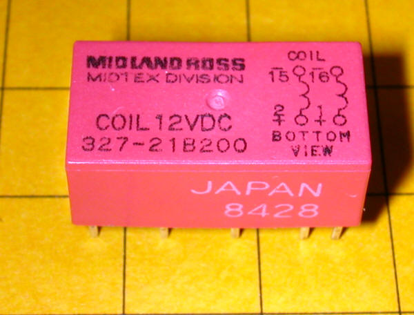
The dual coil latching relay shown below is rated at 2 amps and fits into a standard 16 pin IC socket. You can see a representation of the two coils on the label. One goes between pins 1 and 16 and the other between pins 2 and 15. Note that these coils are polarity sensitive, that is it matters which end of the coil connects to positive and which connects to negative. The + and - symbols by the pin numbers indicate which pin connects to positive and which goes to negative.
Simple Auto-reverse Controller
The DPDT dual-coil latching relay can be used to create what may be the simplest auto-reverse controller you can make. Auto-reverse controllers are frequently used to operate a trolley or other small engine on a single run of track. The trolley goes to one end, reverses and proceeds to the other end where the back & forth operation continues.
To wire this controller replace the two push button switches in the diagram above with magnetic reed switches. (See Garden Railway Sensors - Part 1 for more information on reed switches) Then glue a magnet to the bottom of an engine or trolley so that it passes directly over each of the reed switches as it travels back and forth. It will trigger the appropriate coil to change the polarity as the train reaches the end of a point-to-point track. Place the reed switches between the rails a few inches before the diodes at either end of the track. The diodes are optional and are only there to stop the train should the reed switch fail to sense the magnet passing over it. Note that the diode's banded ends, the cathodes, face to the right at both ends of the near rail. This is the way they must be installed for G scale. If you want to try this with HO and smaller scale layouts you need to reverse both diodes.
This circuit will automatically reverse the engine as it reaches the end of the track. Unfortunately that reversal will be abrupt and may be hard on the engine's gearing. The next circuit will help to make this less of a problem.
Diodes Slow Things Down Gradually
This version adds pairs of diodes to the ends of the point-to-point. These sets of diodes will gradually slow the train as it nears the end of the line. Most common diodes will drop a voltage going through them by approximately 0.7 volts. This circuit will first slow the train a bit by dropping the voltage by 0.7 volts then a bit more by another 0.7 volts and so on until the reed switch is encountered. Note that there are two diodes wired back-to-back at each block. This is so that the train can go in either direction through the blocks. Additional blocks can be added to slow the train more and more. Just be sure that there is enough power at the last block to allow the train to make it to the reed switch rather than just stopping short! (Even though the sets of diodes are shown very close together in this drawing on a layout there would be one or more feet between each set.)
Relay Size
The dual coil latching relay that I used for developing this article may seem small and not capable of handling large scale engines. After all it is less than 1" long!
That was my feeling until I did some testing. I put together a test track that was composed of 20 feet of track with a reed switch at either end. I set up a small AristoCraft 0-4-0 switcher with a magnet glued to its underside and ran a test using this latching relay. The train ran back and forth for 5 hours without a hitch. I am sure it would have run longer but I got tired of hearing the locomotive spin its wheels every time it reversed! Keep in mind that the test did not employ the extra diodes as shown above so the full electrical load from the engine was switched hundreds of times without a problem. I ran the train at 14 volts and the current draw was a bit under 0.5 amps. I also ran tests for a shorter time with voltages as high as 18 volts and as low as 6 volts and the relay continued to perform flawlessly even though its rating says it is for 12 volt circuits.
If you were to run larger engines on such a point-to-point there is little doubt that you would fry or fuse the contacts on the relay. One solution is to either find another dual coil relay with contacts rated for more current. A search through Digikey returns several. A simpler solution is to wire a common DPDT single coil relay to one set of the dual coil relay's contacts so that the smaller relay does nothing more than activate the larger relay. The schematic below shows one way to accomplish this.
Reverse Loop Controller
With very minor changes this circuit can be used to have a train automatically navigate two track configurations that typically give track powered operators problems.
The first is a reverse loop where a loop of track is connected to a main line by a single turnout.
When the train is moving from left to right and enters the turnout it goes one way or the other around the loop and exits back onto the main line facing in the opposite direction. If you follow one of the rails from the turnout and around the loop until it meets back up with the turnout you can clearly see the problem since the lower rail on the main line connects directly to the upper rail on the main line at the other end of the loop creating a short circuit. Such a short circuit is OK if you are using battery power or live steam but bring things to a stop if you operate under track power.
The second troublesome track configuration to use with track power is a wye. A wye uses three turnouts to accomplish the same thing as the reverse loop but in an entirely different way. In a wye the train must stop and reverse direction twice as it goes through three switches.
If the train is going straight up in the diagram above from the point marked "Start" and "Switch 1" is set to have it go to the right it will enter the siding in the upper right through "Switch 2". At the point marked "Reverse 1" it must stop and reverse. The train reenters "Switch 2" which is set so that the train travels straight across to "Switch 3". The train reverses again at "Reverse 2". "Switch 3" is set so that the train goes to the right back to "Switch 1" and to "Start". Note that the train will be facing the other direction after traversing the wye. Another examination of the rails will show you that there is a dead short between them.
Note that neither of these layouts require powered turnouts. The switches are all spring loaded so that the train can enter when the points are going the wrong way without derailing. The spring allows the points to move but returns them to their initial setting once the train has passed. Most "G" scale switches, and many for other scales, work this way. As long as your engines and rolling stock are not extremely light in weight the switch points will be safely pushed aside as the train passes.
Isolating a Reverse Loop or Wye
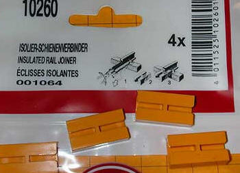
In order to allow the trains to progress through the reverse loop or wye both rails of the track within the loop must be physically isolated by insulators. Three different types of G scale insulators are show here:
LGB’s 10260...
AristoCraft’s 11901...

and Hillman Rail Clamp's #332-01PSA .
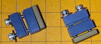
To use these isolators just remove the metal rail joiner and substitute the insulator.
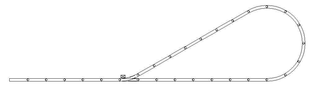
The track in the loop must be completely isolated by breaking it at four points and adding insulators at these locations. This can be seen in the illustration below.
Supplying Power to the Isolated Section
Power is supplied to the isolated section either through a bridge rectifier or by wires run directly from the train's power supply that bypass the DPDT switch. Connecting directly to the power supply is shown here. It is the simpler method but may require long power wires if your reverse loop is some distance from the power supply.
In the diagram above the positive lead from the power supply goes to the outside rail through the DPDT switch as does the direct line from the power supply. The negative connections both go to the inside rail. This causes the train to move from left to right on the main line and, if the switch is set to straight, to go around the loop in a counter clockwise direction. There is a problem that comes up, however, when the train crosses the gap in the top of the loop. The polarity it encounters tries to have it return to the loop while the polarity in the loop forces it out. Not a good thing. We have to arrange for the polarity of the main line to switch from positive on the outside rail to positive on the inside rail so that the train continues on in the same direction as it exits the loop. This can be done by throwing the DPDT switch and reversing polarity while the train is in the loop. The polarity in the loop stays the same but the polarity on the main line is reversed.
A Bridge Rectifier Works Well, too
A bridge rectifier is used in this modification of the circuit. Although a bridge rectifier is generally used to convert an AC voltage to a DC one it can also be used to take a DC voltage of either polarity and always supply a consistent positive and negative voltage. Here the bridge gets its input from the main line and connects its output terminals to the loop. It always delivers a positive voltage to the outer rail and a negative voltage to the inner rail. This guarantees that the train always goes through the loop in a counter clockwise direction. While the train is in the loop the DPDT switch can be used to reverse the polarity on the main line so that the train continues to run in the proper direction as it exits the loop.
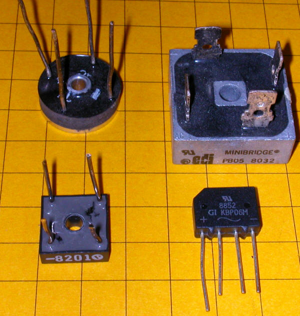
This photo shows several different bridge rectifiers. All of them have one of their four pins marked with a "+". The pin opposite the "+" is "-" and the two other pins are the input pins, sometimes marked with a "~" to represent alternating current.
The advantage of using the bridge rectifier is that you can pick up power from the main line right before the switch and feed it to the bridge. This has the potential to shorten the amount of wire that must be used, especially if there is a great distance between the power supply and the loop. The only disadvantage in using the bridge rectifier is that the train will slow a bit in the loop as the bridge drops the voltage by a little more than one volt.
To automate the train's operation in the loop the DPDT switch is replaced by a dual coil DPDT relay. The coils of the relay are connected to reed switches that are placed under the track somewhere within the isolated track in the loop. When the magnet under the train passes over the reed switch the polarity in the main line is reversed so that the train can exit the loop and continue on its way onto the main line. Because the loop is being fed by the bridge rectifier the polarity within the loop never changes.
The diagram above shows a double reverse loop layout. Both switches are set to have the train enter the loops through the straight path. The two LEDs, D1 and D2, are optional and are used to show the polarity of the voltage on the main line.
The two layouts can easily be combined so that there is a reverse loop at one and a reversing section of track at the other as shown below. Remember that the last diode on the left is optional and must come after the reed switch.
A another word about the reliability of this circuit is in order. A public display with two reverse loops was recently set up and operated by the Pittsburgh Garden Railway Society. I am happy to report that it operated without problems for three days, a total of well over 20 hours. Since there is very little current going through the relay when it is switched the relay is under very little stress and is likely to last indefinitely.
Wye Controller
The wye controller shown here uses components of the circuits that we have already used. The train needs to reverse direction twice, once at either end of the straight section at the top. The polarity needs to be reversed one more time so that the train enters the main line and continues moving in the proper direction. This is accomplished by the isolated section just above the left hand side of Switch 1. A third reed switch, wired in parallel with SW 1, reverses the polarity while the train is in the isolated section that is fed by the bridge rectifier.
I built and tested each of these designs with G scale track and engines. I also built a wye, as above, with a reverse loop at each of the upper ends and a simple reverse at the bottom. Because of space limitations in my workshop it was done in HO scale but I have no doubt that it would work with G scale as well. The drawing below shows a variation on that layout with a wye, single reversing loop and two reverse sections. All of them controlled by nothing more than four reed switches and one relay!
Custom Circuit Board
To make things even simpler and more reliable I had circuit boards fabricated to hold the dual coil relay and connections to the reed switches. It also has space for the two indicator LEDs.
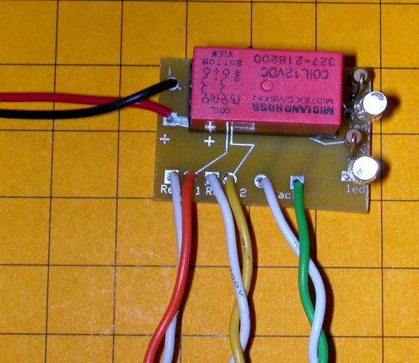
The black and red wires connect to the positive and negative terminals of a DC power supply or transformer. If you use a transformer that has a forward/reverse direction switch make sure that you set the direction control so that the red wire gets positive and the black negative or the relay will not work properly.
The reed switches connect to the red/white and yellow/white wires. The green/white pair of wires goes to the track. The two LEDs to the right are optional and just show which way the relay is latched.
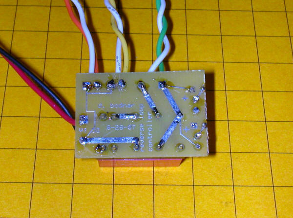
The bottom view of the completed board confirms that there isn't much to this circuit!
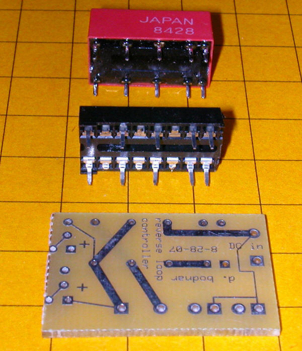
This view shows the relay, its socket and the circuit board. I used a socket so that a burned out relay could easily be replaced. So far there has been no need! Note that some of the socket's pins have been snipped off to match the pins on the relay. Make sure you put the relay into the socket in the right direction or it is sure to disappoint you!
I hope that you have an opportunity to experiment with dual coil latching relays and find them as useful as I have. I have a few circuit boards, reed switches and extra relays on hand. Drop me an email if you would like to use any of them and, as usual, please let me know if I can help.