| A new company,
Precision RC, recently began distributing and supporting
the Train Engineer Revolution radio control system for G-Scale,
O-Scale and
HO-Scale model railroads.
While most of the products are cosmetically and functionally identical to the ones offered by Aristo Craft and Crest Electronics there are several new items that will be the focus of this discussion. These are the Linear Base Station and the USB Interface. For more information
on the other Revolution receivers please see: |
|
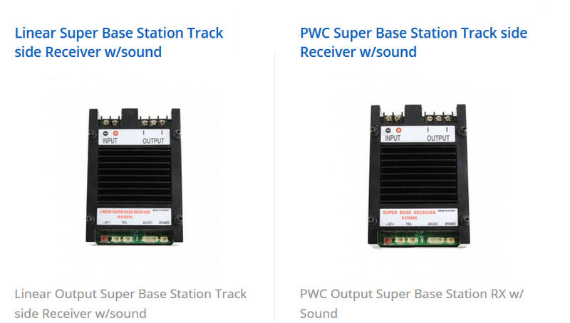
| Linear Super Base Station A new offering from Precision RS is a Linear Super Base Station that can be used either track-side or on-board trains. When used track-side it can be a replacement for the original Train Engineer that was sold by Aristo Craft for many years.
The Base Station receiver is available with
either PWC or Linear output. The manuals for these units is
available here:
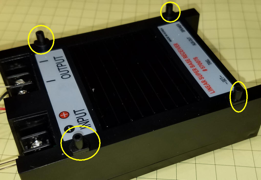
The PWC version of the Base Station is almost identical to the one that was originally produced. The only visible difference is the addition of four pins on the top of the case to allow for mounting a cooling fan.
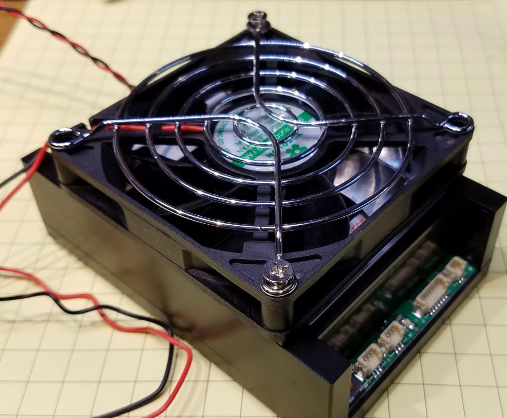
The fan does not get screwed to these pins but simply is placed on them to align its position on top of the receiver. The power leads from the fan need to be connected to the input power screws putting the red wire to Positive (+) and the black to Negative (-).
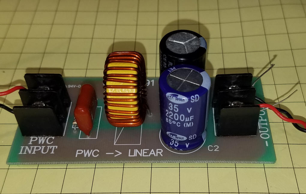
While orienting the fan as shown above (with the label facing up) might make sense I believe that better cooling will take place if the fan's label faces down which will propel cooling air down rather than exhausting air from the heat sink. The Linear Base Station includes an internal filter that converts PWC (also called PWM - Pulse Width Modulation) to a pure linear DC signal. This was done with the old Base Station that was only available as PWC by adding a PWC to Linear converter between the receiver and the track or engine.
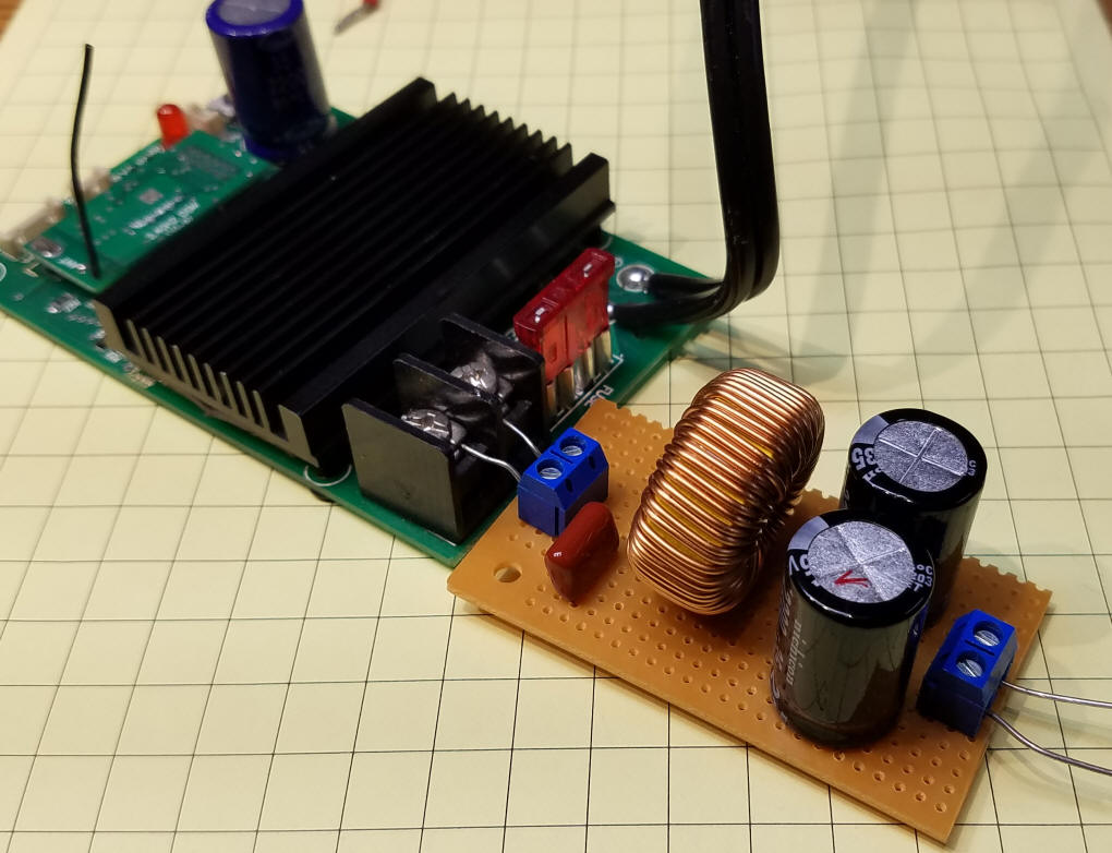
Here the original Base Receiver (that was shipped without a case) is connected to a converter that I made from a resistor, three capacitors and an inductor.
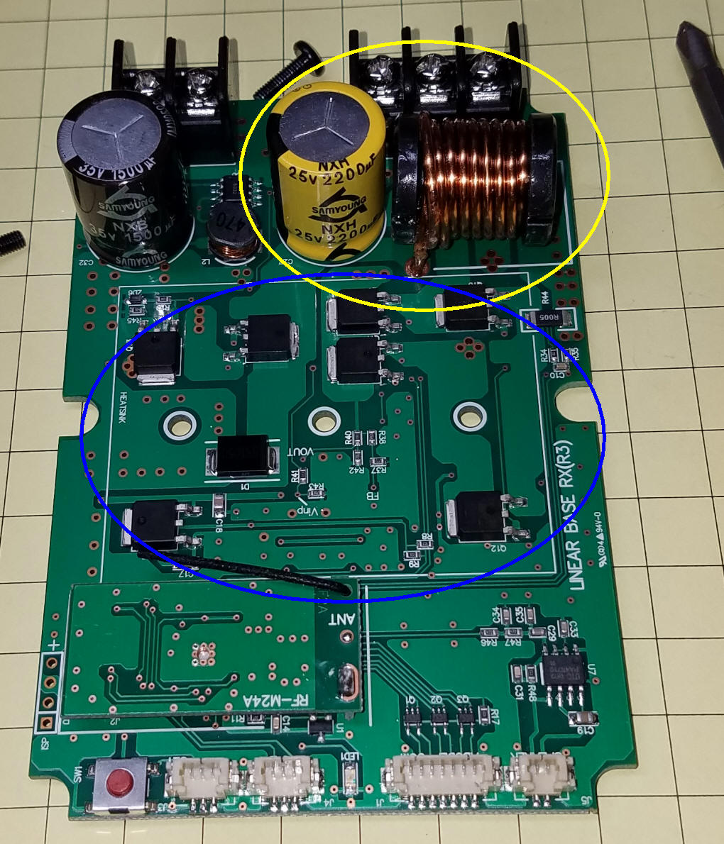
The new Linear Base Station contains similar components within the same case that is used with the standard PWC system. This photo shows the Linear Base Station with the case and heat sink removed. The PWC to Linear converter components are circled in yellow. The components that make up the power controller are circled in blue and normally reside under a large aluminum heat sink.
|
|
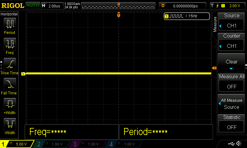
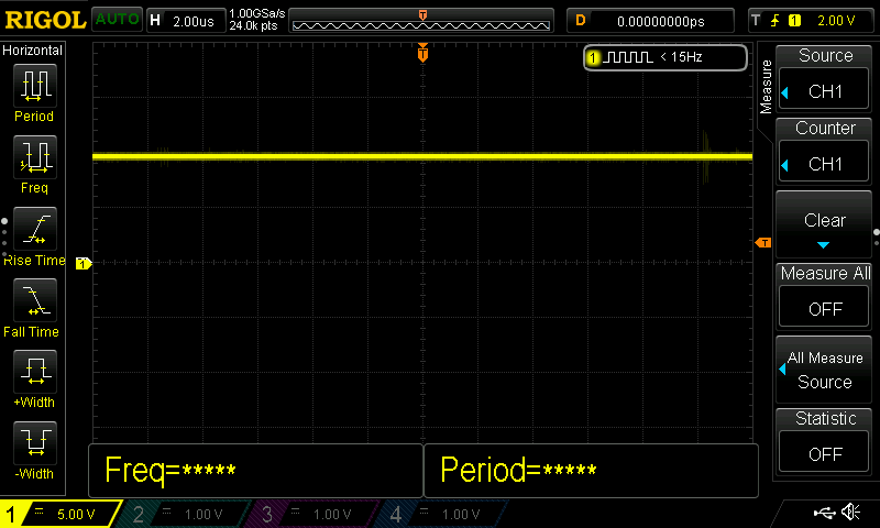
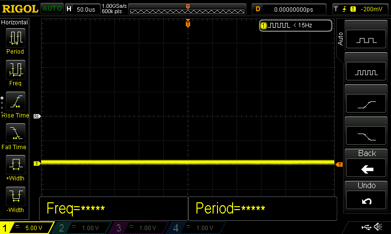
| Linear Output vs. PWC Output For many of us the difference between the two receivers is not a concern as many locomotives and their sound cards & electronics can tolerate either type of power. Some engines, however, just don't work properly with PWC. A discussion of the difference between them might shed some light on this issue. Linear power is what we get from a traditional analog DC power supply. When the throttle knob is turned up the DC voltage increases in a linear manner. A 20 volt power supply should deliver about 10 volts of clean DC power when set to a 50% throttle position. This can be seen visually by feeding the output from a power supply to an oscilloscope. The images below are from the Linear Super Base Station. The first image shows the output when the throttle is set to zero. Each vertical division represents 5 volts. The power supply was delivering 20 volts and a DC motor was connected as a load. Please take note of the location of the horizontal yellow line. It represents zero volts.
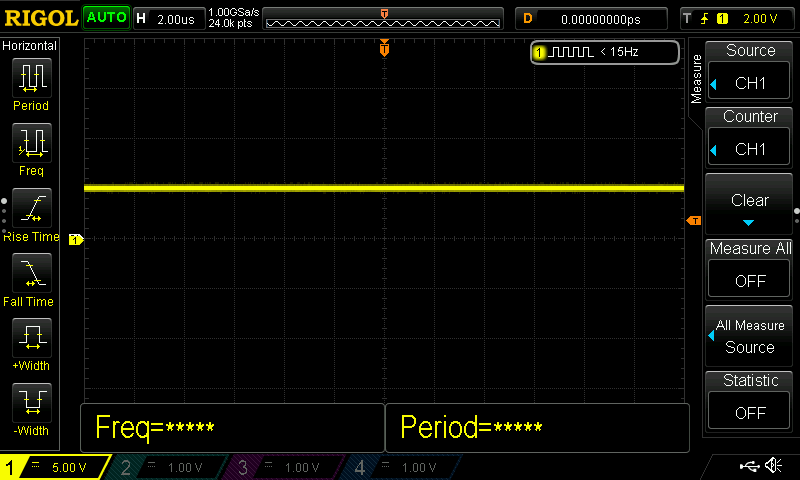
Here the throttle has been advanced to 25%. The line is higher by one division on the screen or about 5volts. Note that no value is given for "Freq" indicating that the output is pure DC.
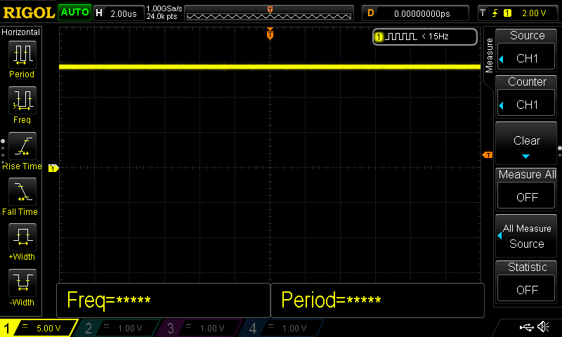
Here the throttle is at 50%. The line has jumped up another 5 volts.
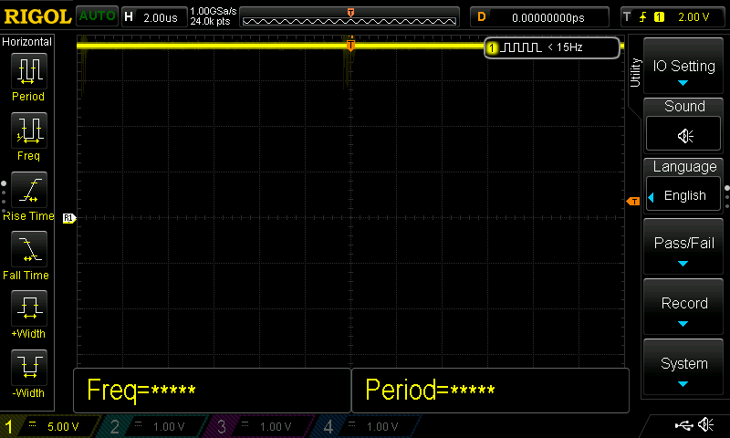
This is 75% throttle and...
... this is 100% throttle.
When the same tests were run with the PWC Base Station the display is dramatically different. The first image shows the PWC Base Station at zero power. Note that I moved the base (zero) position down so that the rest of the images would fit on the screen.
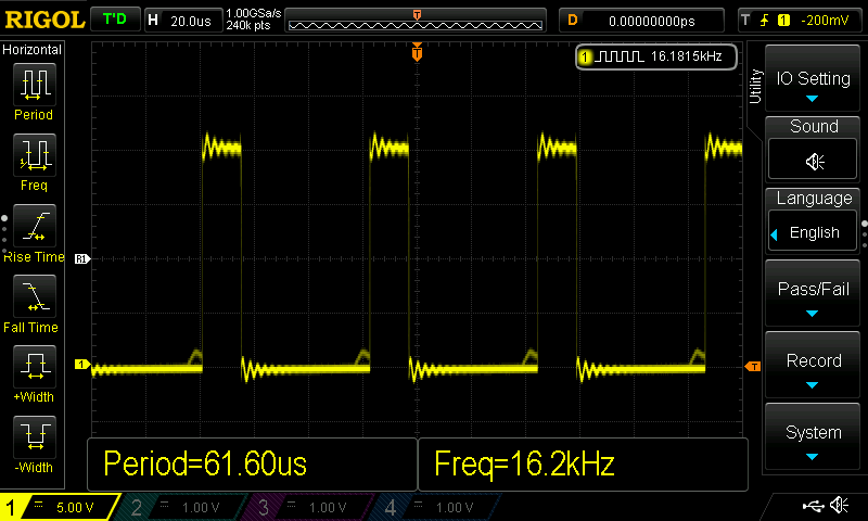
Here the throttle is set to 25%. The graph shows that the full 20 volts is applied (shown by the spikes) for a short time (approximately 25% of the time - logical, eh?) and that the power is off for about 75% of the time. On average, the motor and electronics on the engine would see about 5 volts (25% of the supplied 20 volts).
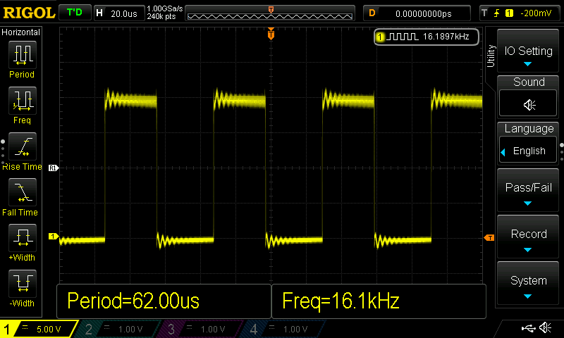
Here the throttle is at 50%. The power is on for about 1/2 of the time and off for about 1/2.
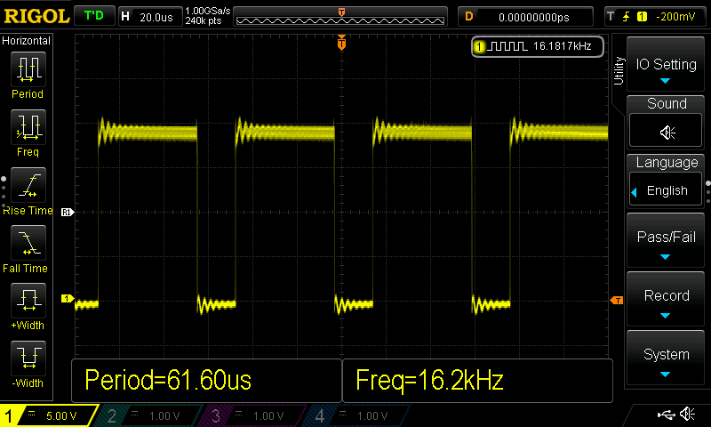
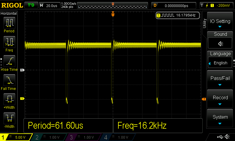
This is 75% and...
... this is full throttle where the power is on for almost all of the time. You should also note that these on/off pulses are delivered at a frequency of 16.2 kHz or about 16,000 times per second. The period tells that the time between pulses is a bit over 61 microseconds.
The Linear Base Station is a welcome addition to the Revolution family. It is ideal for those of us who may be using trains with sensitive electronics that cannot handle PWC (PWM) based power. |
|
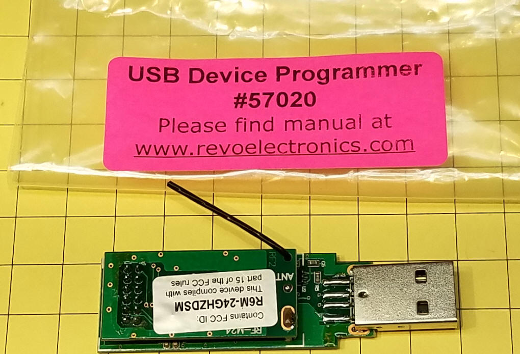
| USB Device Programmer The other item that I would like to highlight is the USB Device Programmer, part #57020.
This programmer is intended to allow users
to reprogram their transmitters, receivers and other devices and to
update sound files for their receivers. The programmer's
manual is here:
http://www.revoelectronics.com/media/wysiwyg/USB_manual.pdf
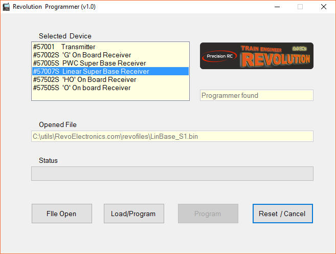
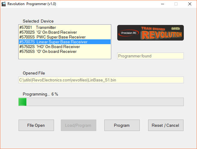
Installation on my Windows 10 computer went through without a problem. No drivers were needed. Just insert the USB device and run the downloaded program which can be found here: http://www.revoelectronics.com/blog/ You will see a screen similar to this. If the programmer is connected "Programmer found" will appear in the upper right. Select the appropriate device (in my case I chose Linear Super Base Receiver) from the list of options. Click the File Open button and navigate to where you saved the sound files.
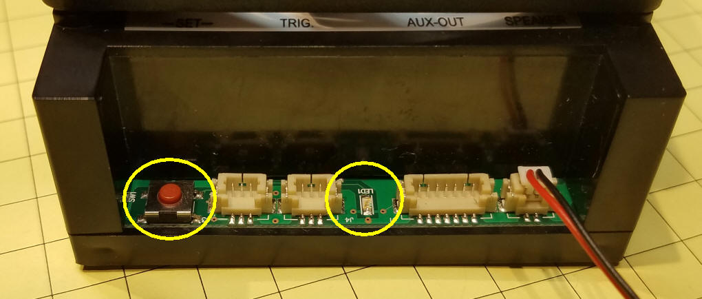
Once this is all ready turn off the power to all of your receivers and transmitters. Turn on ONLY the unit to be programmed. Press and hold the linking button on the receiver until the blue LED blinks rapidly then blinks more slowly. Release the button.
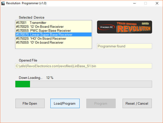
Click the Load/Program button and the fist step, downloading, will begin. At this point the blue LED on the receiver should be on and the two LEDs on the USB programmer should be on solid red and solid blue. While you might think that the process of "downloading" would be sending data to the receiver it is actually an internal process where the file is "downloaded" to the program, not the receiver.
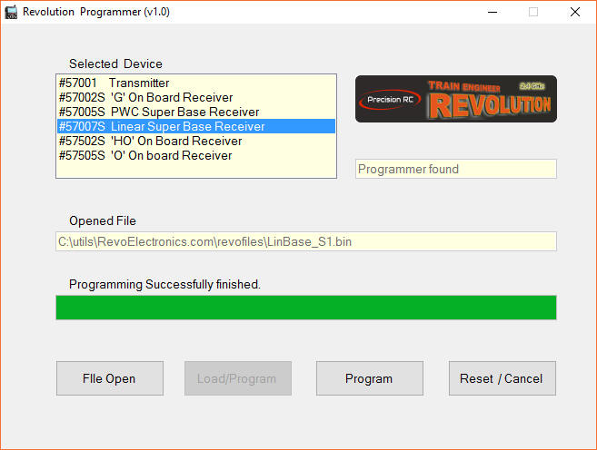
Downloading will continue to 100%. Once that is complete the data will be sent to the receiver or other device. This is called Programming. When the programming begins the blue LED on the receiver will blink as will the red LED on the programmer.
Once the process is complete the screen will show "Programming Successfully finished" and the LEDs will stop blinking. This can take several minutes.
At this point the receiver or other device is ready to use. I have not had a need to program the transmitter as it has the most up to date software but I am confident that it will work as well as the receiver update that I did here. |
|
| Conclusion I am pleased to see that the Revolution family of radio control components is alive and well. I think the addition of these two components and the upcoming release of additional sound files shows that the new company has a commitment to making this a superior choice for operating our railroads! |