Revised 10-29-09
newer receiver repair
6-29-18
The Revolution's receiver can be damaged by inadvertently applying voltage to the motor output pins on the device. This can happen if track pickups that go to a locomotive's wheels are not disconnected or if one incorrectly wires the receiver connections.
The symptoms of such damage can include:
Overload being reported when power is applied to the locomotive
The train operates in forward but overloads in reverse
Fuses blow when power is applied
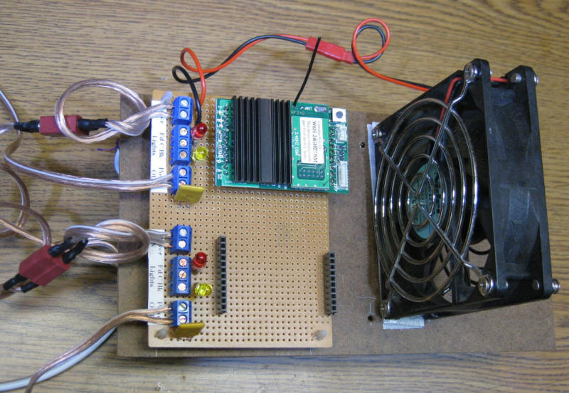
My first experience with this type of damage occurred when I built a track-side control unit for use at a Pittsburgh Garden Railway Society train layout.
It supports two receivers (only one is installed in this photo) and takes power from a 20 volt power supply and feeds it to the receivers that then supply power to the track.
While connecting this device to a track that was already running a train I made the fatal (for the Revolution!) error of connecting to a live track. The back-voltage from the live track went into the output of the receiver and damaged it. The receiver would run a train in one direction but would immediately shut down when reversed.
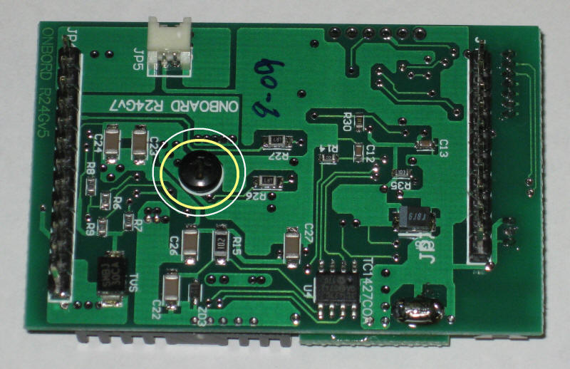
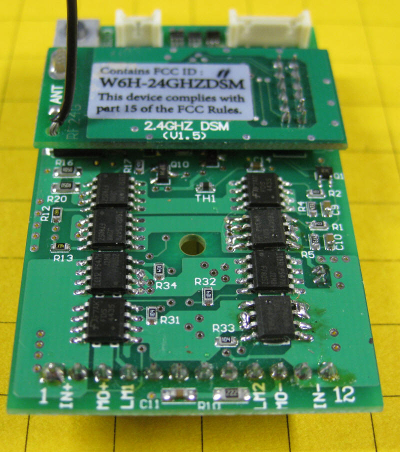
When I returned home I disassembled the receiver to survey the damage. The heat sink has to be removed to gain access to the part of the board that I needed to examine. This is done by removing the black screw on the bottom of the board.
The heat sink and the rubber heat sink pad should come off easily.
The group of eight 8 pin integrated circuits are Mosfets. The bottom four are used to select the polarity of the track or battery power and they replace a bridge rectifier that would normally be used for this purpose. The advantage of using Mosfets is a lower voltage drop to the circuit and less heat generation. The disadvantage is that the board cannot operate from DCC or AC track power without the addition of an external bridge rectifier board. Two of the four bottom Mosfets are N-Channel and two are P-Channel.
The upper four devices are wired to create an H-Bridge that is the electronic equivalent of a DPDT relay with speed control. Again two are N-Channel and two are P-Channel.
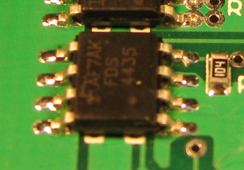
The devices are Part # IRF7805ZTRPBF (N-Channel) and Part # FDS4435 (P-Channel).
To determine which Mosfets may be damaged place an ohm meter across the Source and Drain contacts. The Source pins are the three on the right in this photo and the Drain contacts are the four on the left. The other pin (upper right) is the Gate.
Measure the resistance across these pins. If it reads zero ohms in both directions (red to Drain / black to Source & red to Source / black to Drain) then the device is shorted and needs to be replaced.
In my case I found the bottom right device (next to R33) and the one two above it to be bad. They are both P-Channel Mosfets.
If you have never worked with surface mount components it is best to find someone who has to do the repair. Also keep in mind that attempting this repair and/or opening up the unit will likely void any warranty coverage. I was responsible for frying my unit so I couldn't, in good conscience, return it for a warranty repair so I had nothing to lose.
If you want to give it a try follow these steps:
Remove the heat sink screw
Take note of the heat sink's orientation. I marked mine so that it would go back the same way it was set at the factory.
Remove the heat sink. The rubber pad should stay on the heat sink. Leave it there.
Note the location of pin 1 on the chip. This is the pin with a small dot next to it. In the photo above it is the pin in the lower right corner.
Use a small set of wire cutters (sometimes called side cutters) or a sharp razor knife to cut the pins from the chip where they enter the plastic case.
Leave the rest of each pin soldered to the board
Carefully remove the chip taking care not to pull on partially cut pins and damaging the pads on the board.
Use a fine tipped soldering iron to remove each pin from its solder pad.
Clean off as much of the remaining solder as possible using the iron and, if necessary, solder wick.
Place the new Mosfet in the same direction as the one that was removed
Solder each pin to its trace on the board.
Don't worry about solder bridges between the Source pins and the Drain pins as they are joined together on the board.
DO NOT allow a bridge between the Gate and the Drain!
Put the heat sink & pad back on being sure that the indentations on the pad align as they did before.
Test at very low voltage. If possible use a variable power supply that has an ammeter so that you can bring the power up slowly while monitoring the current draw. If the current draw spikes shut down and check your wiring!
Good luck!
Notes on Another Heat Conductive Pad
After working on this receiver I was intrigued by the rubber pad that goes between the Mosfets and the metal heat sink. I spent some time on the Internet found a manufacturer in Taiwan and ordered some samples.
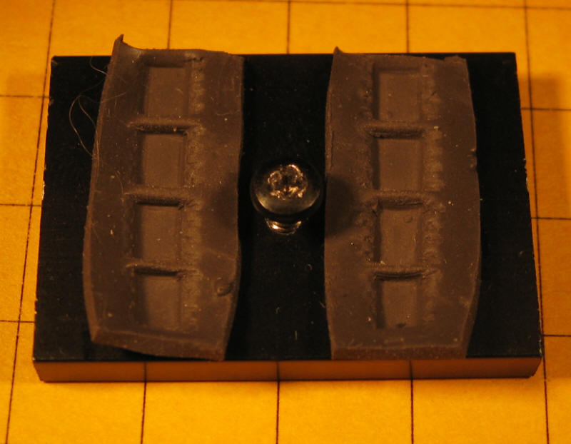
The two samples that I received are 10 cm x 10 cm in 2mm and 4mm thickness. The 4mm sample is shown here.
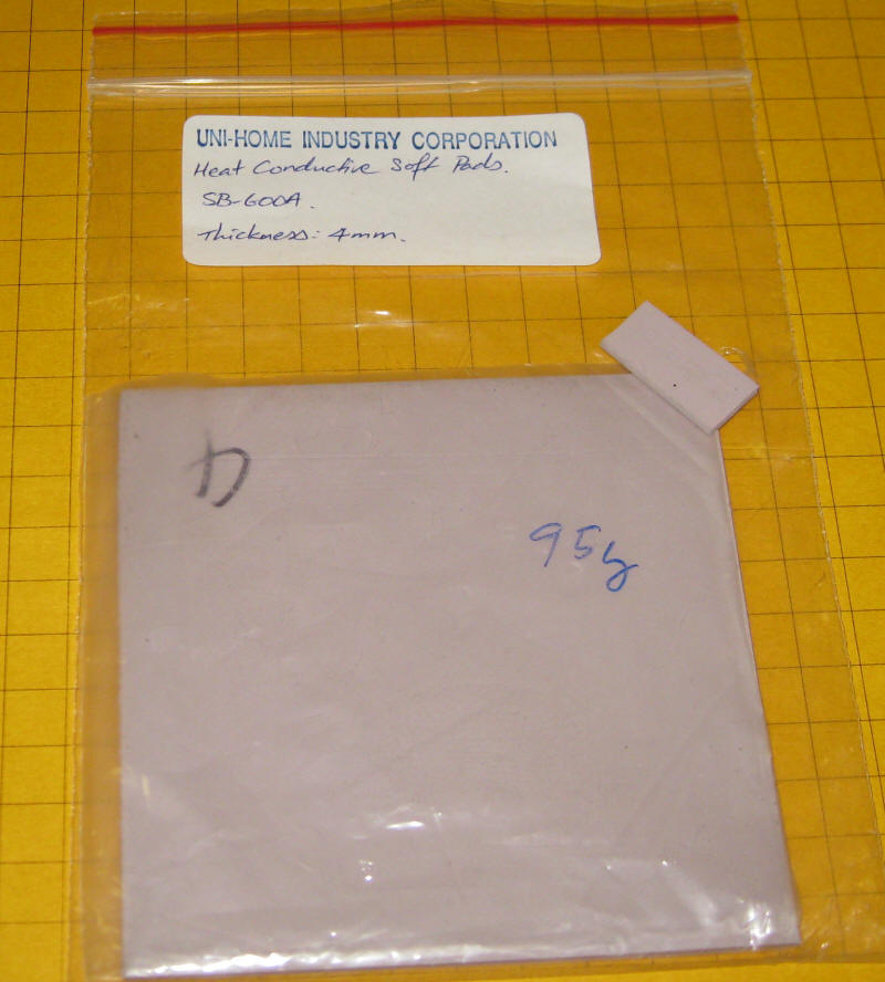
Technical data on the material is available here: http://www.uni-home.com.tw/userfiles/file/20091009182150.pdf
Test Results & Observations
I cut two pieces of the test material to the same size as the original and inserted them between the Mosfets & the heat sink. Here you see the material after it was removed. Note that the impressions of the ICs are not as distinct as they were with the original material. This may be due to its being more dense and less pliable.
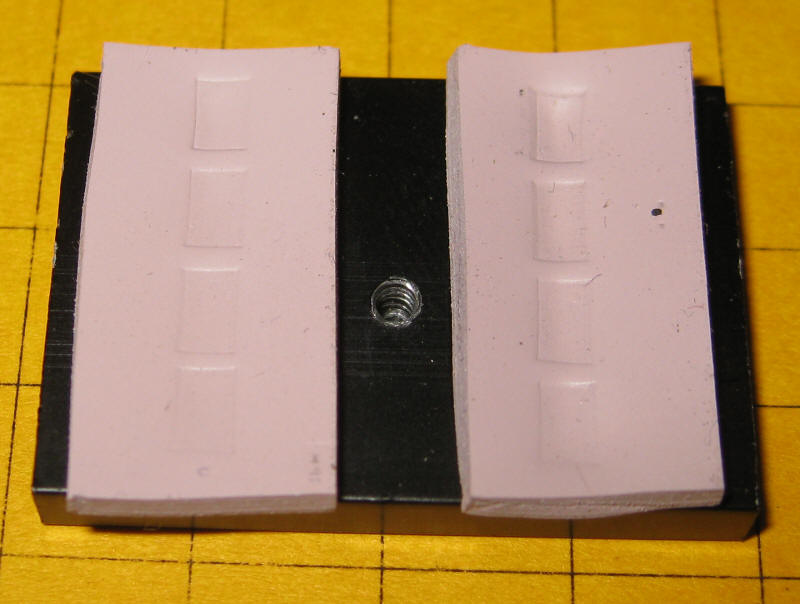
I ran the Revolution receiver with both the original thermal material and the test material. Tests ran for 5 minutes at 18 volts. The receiver was running three small locomotives on rollers. The current consumption was 2 amps.
After heating up for 5 minutes the temperature of the heat sink was measured. With both materials the temperature stabilized at 112 degrees indicating that the materials are doing the same job of transferring heat to the heat sink.
The test material differs from the original material in several ways:
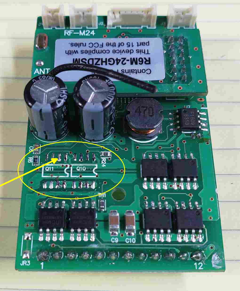
The newer Revolution receivers with sound don't use N-channel & P-channel Mosfets. They use a single chip that has both N & P channels - I recently was asked to repair such a receiver and found the proper chip (a 4606 POWER MOSFET) that I could purchase on eBay.
Symptom: The receiver worked properly in one direction but, when reversed, immediately showed an overload.
Test: I used an ohm meter to check for shorts between pins on the Mosfets. Note that all of the bottom pins (numbers 5, 6, 7 and 8 are connected together on the board. I found that the two chips in the upper left had a short from pin 2 to 5, 6, 7 and 8 - pin 2 is the one at the end of the yellow arrow.
I replace the two failed Mosfets (see photo below) and the unit came back to life.
OTHER FAILURE ISSUES
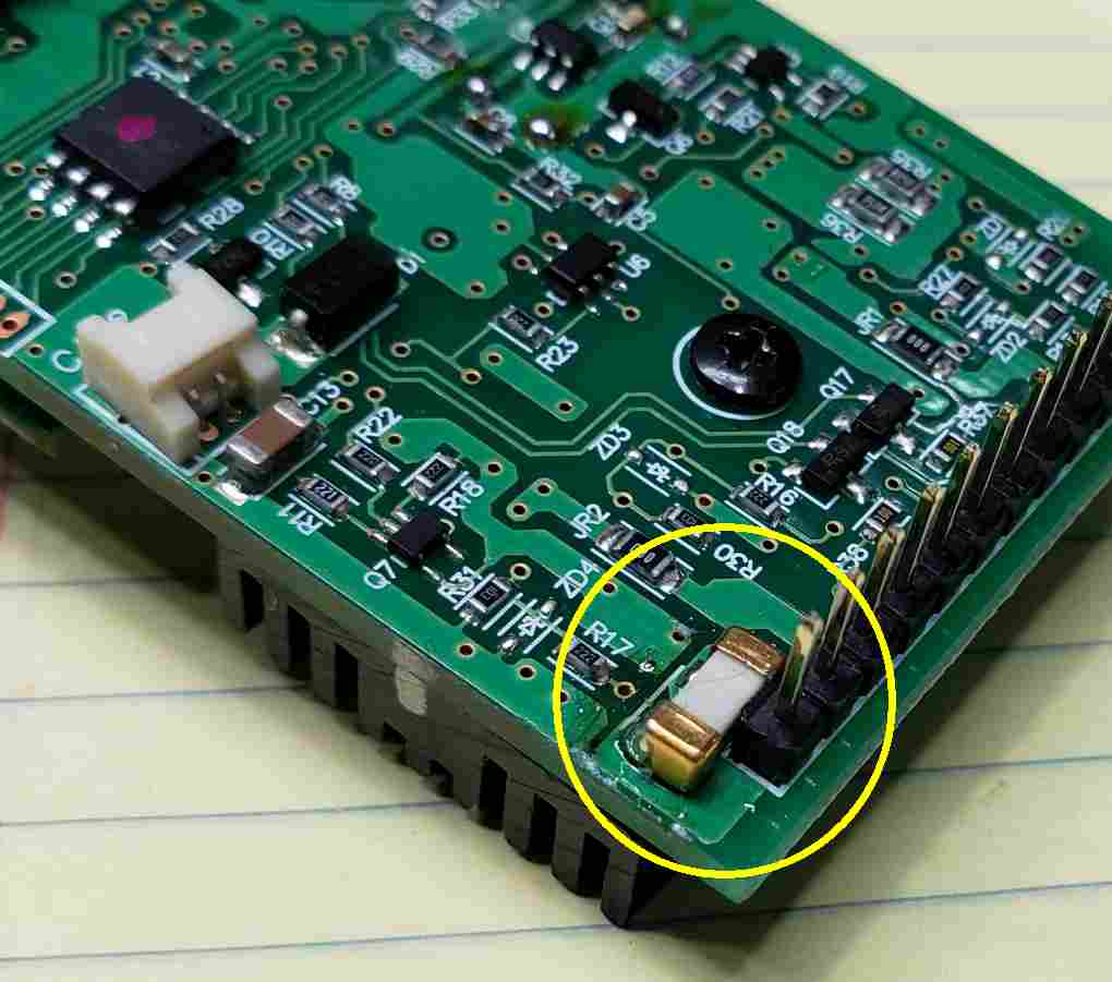
Other Revolution receivers that I have been asked to repair suffer from a failed surface mount fuse that is mounted directly to the receiver board.
This photo shows the factory installed fuse (circled in yellow) It is a 5 amp surface mount device that can be found on eBay. I have found this to be a very common source of failure.
Symptom: The board is completely dead & unresponsive
Test: Check the resistance between the two sides of the fuse. It should be zero ohms (or close to that). If it is open (infinite ohms) that may indicate that it has failed.
As a work-around (for testing) you can solder a thin piece of wire across the terminals - If the board works you have found the problem.
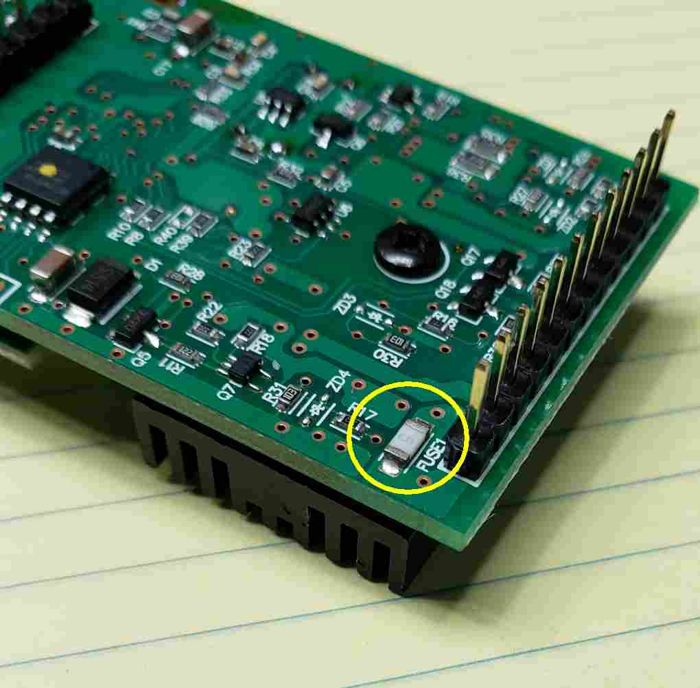
I ordered replacement devices from eBay. Unfortunately the ones I received were physically larger than the factory devices. I was able to get them to install but with some difficulty. The size that you should try to find is a 1206.