Servo Animation with
Multiple Sounds
d. bodnar 12-12-15
A demonstration video is here:
| Introduction I made my first servo controller many years ago (see: http://www.trainelectronics.com/Animation_servos/index.htm ) and have used servos in many animations. Frequently it made sense to add sound to the movement that the servo provided so I have used my servo controllers to trigger an external sound unit of one sort or another. This worked well but it was frequently a challenge to synchronize the sound clip with the movement of the servo. When I recently revised my original servo controller to add to its functionality and make it easier to set up I decided that it would be a good time to make the sound synchronization easier, too. This involved designing a new circuit that would include both a microcontroller to operate the servo and a separate MP3 player that could be used to play multiple sounds that I could synchronize with different events in the servo's operation. The new controller is described here. Pressing the "start" button initiates sounds and movement of the servo from its start position to its second position and back to start. A total of six different MP3 files can be used to accompany the servo's movements. The unit is controlled by a PIC 16F684 microcontroller. I may make an Arduino based unit so that more users can have the opportunity to reprogram the system to more closely meet their needs. |
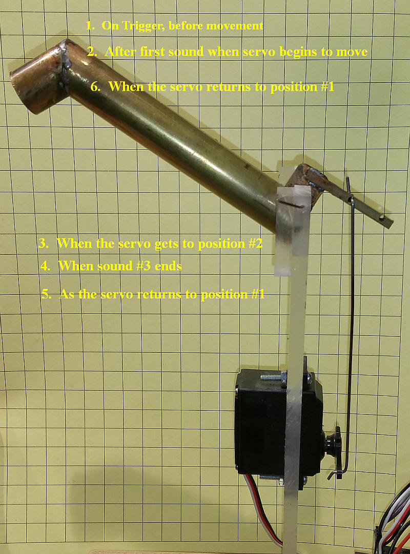
| Sound Options In a servo operated animation, such as lowering a fill nozzle from a track-side water tower, there are six different events in the movement of the nozzle that can have different sounds attached to them. These are:
Note that any of these sounds can be silent and of such a short duration that they are essentially skipped. You can also use silent sound clips of whatever duration to insert pauses in the servo's operation.
In this water tower nozzle example
|
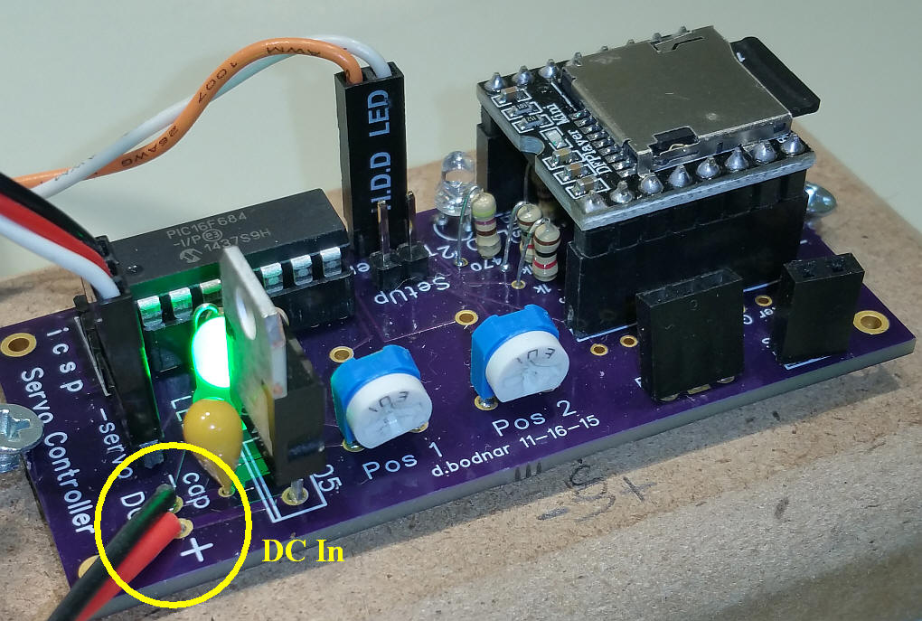
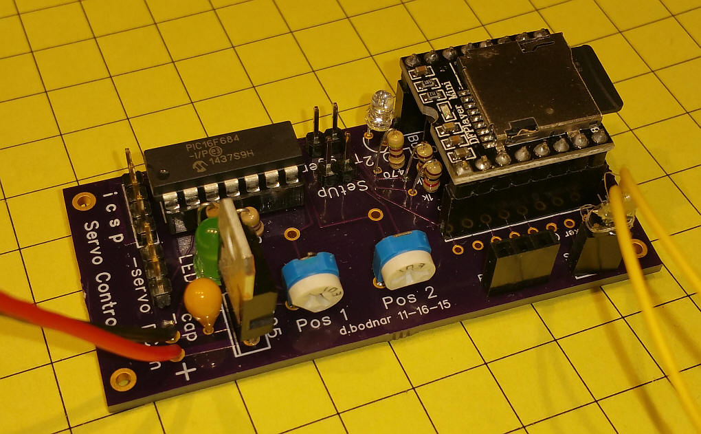
| Hardware Setup Connect power to the DC in pins, positive voltage to + and negative to -. Power should be between 7 and 12 volts and must be "clean" DC, not unregulated and unfiltered power or the unit will work poorly.
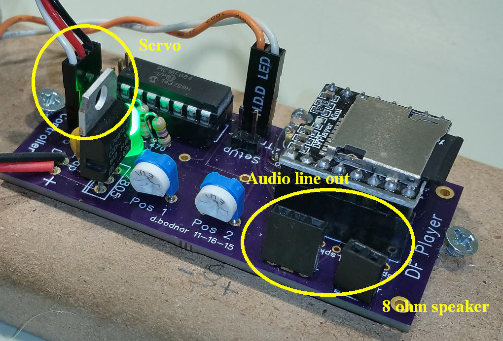
The two potentiometers, labeled Pos 1 and Pos 2, are used to adjust the position of the servo when in Setup mode. The Pos 2 potentiometer is used to adjust the speed of the servo movement when not in Setup mode. The servo connects to the 3 pins by the power input pins. The negative lead (usually black or brown) must go towards the - sign in the label that reads "-servo". It the photo the negative lead is to the right.
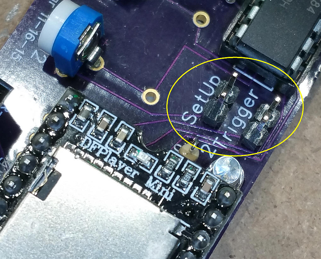
You can connect an 8 ohm speaker to the two pin header or a set of powered speakers can connect to the three pin, audio out header. A push button switch is connected to the two pins labeled "Trigger". A jumper is placed on the "SetUp" pins to enter the setup mode.
|
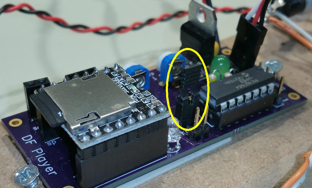
| Setting up the Servo Place a jumper over the two "SetUp" pins to enter setup mode. Note that the green LED will blink dimly.
Use the left pot (labeled Pos 1) to adjust the start position of the servo. When done press the Start button once and the LED will light brightly. Now use the right pot (labeled Pos 2) to adjust the servo to its second position. You can press the Start button to see the two servo positions. When done remove the jumper. Press Start to test. You can skip all of the MP3 files by removing the microSD card before testing.
|
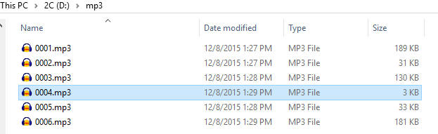
| Sound Files The unit uses up to six MP3 files. These are placed on the microSD card in a directory called mp3
File one is titled 0001.mp3, file two is 0002,mp3 and so on through 0006.mp3.
Remember that the MP3 file length determines how long events 1, 3, 4 and 6 last. Files 2 and 5 play while the servo moves and must be matched to the time it takes for the servo to more. If you want to skip a file, for example #4 above, you still need a file called 0004.mp3 but it should be a short, silent file. |
| Recording Sounds The MP3 files were created in Audacity (see: http://audacity.sourceforge.net/ ) - some information on using Audacity is here: http://www.trainelectronics.com/MP3_project/#Audacity_-_Sound_Editor ). While it is out of the scope of this discussion to go into great detail about using Audacity some comments are in order. |
| Ordering If you would like to order the complete unit, including a 1 gig microSD card and a small 8 ohm speaker please contact me at dave@davebodnar.com . |
| Custom Software If the operation of the servo / sound controller does not meet your application contact dave@davebodnar.com as custom software modifications are available. |
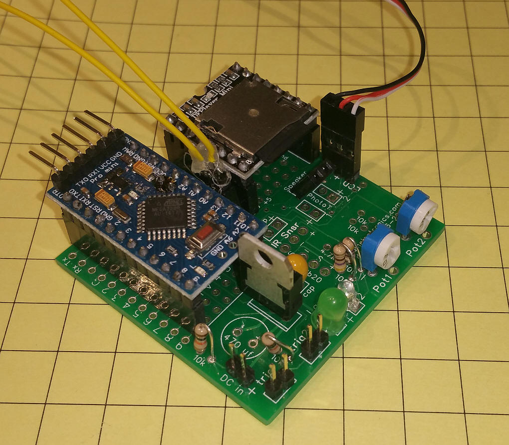
| Arduino Version To enable a wider group of hobbyists to experiment with this controller I have translated the software for the Arduino. The board is from the Defect Detector project. Three of the four wires from the LCD connection are used for the servo.
|
| Schematic The circuit is based on a design that I did for a defect detector. I modified the circuit and used the same circuit board for this controller. Note that pin A4, which connects to the servo, may not be on the edge of the Pro Mini, Mine is on an internal pin just off of the edge.
|
| Software This is the first working version. It is sure to be revised! //*d. bodnar 12-10-2015 port from PIC file for Servo & DFPlayer - v1.1
#include<EEPROM.h>
#include <SoftwareSerial.h>
#include <DFPlayer_Mini_Mp3.h>
#include <Servo.h>
int pot1Pin = A3; // left pot
int pot1Value = 0; // variable to store the value coming from the pot
int pot2Pin = A2; // right pot
int pot2Value = 0; // variable to store the value coming from the pot
const int TriggerButton = 3; // the number of the pushbutton pin
const int SetupButton = 4; // second button pin
const int ledPin = 13; // the number of the LED pin
int buusyPin = 10;// buusyPin = 10; // sound player busy
int bsy = 0;
int z = 0;
long x = 0;
int LED_Green = 11; // LED_Green control
int LED_Blue = 12; // LED_Green control
//String thisString(12);
//int mute = 0; // =0 if talking, =1 if muted
Servo myservo; // create servo object to control a servo
int pos1 = 172;
int pos2 = 90;
int tt = 0;
int buttonStateSetup = 0;
int buttonStateTrigger = 0;
int speedValue = 0;
int MP3file = 0;
//***************************************SETUP*************************************
void setup () {
Serial.begin (9600);
pot1Value = EEPROM.read(0);
pot2Value = EEPROM.read(1);
Serial.println("raw read values");
Serial.println(pot1Value);
Serial.println(pot2Value);
if (pot1Value >= 181) pot1Value = 180;
if (pot2Value >= 181) pot2Value = 180;
myservo.attach(18); // attaches the servo on pin 18 (A4) to the servo object
pinMode(TriggerButton, INPUT);
pinMode(LED_Green, OUTPUT);
pinMode(LED_Blue, OUTPUT);
pinMode(buusyPin, INPUT);
pinMode(ledPin, OUTPUT);
pinMode(TriggerButton, INPUT);
pinMode(SetupButton, INPUT);
delay (500);
mp3_set_serial (Serial); //set Serial for DFPlayer-mini mp3 module
mp3_reset(); // MUST power off/on MP3 player to reset after programming or audio iffy
mp3_set_volume (30); // must remove mp3_reset(); to get this to work
mp3_reset();
delay (400);
digitalWrite(LED_Green, LOW);
digitalWrite(LED_Blue, LOW);
// if ( pos1 > 255 or pos2 > 255) {
// pos1 = 172;
// pos2 = 90;
// };
Serial.println("pot values after read");
Serial.println(pot1Value);
Serial.println(pot2Value);
InitServoToStart;
Serial.println("d. bodnar 12-12-2015 Servo / DFPlayer Controller v1.1");
}
//.......................................LOOP................................................
void loop () {
x = ++x;
//Serial.print(" x ");Serial.print(x);
if (x >= 50000) {
digitalWrite(LED_Green, !digitalRead(LED_Green));
delay(50);
x = 0;
}
//Serial.println("@ Loop");
buttonStateSetup = digitalRead(SetupButton); // 0 is jumper ON go to the setup routine
if (buttonStateSetup == 1) {
DoSetup();
}
buttonStateTrigger = digitalRead(TriggerButton);
if (buttonStateTrigger == 1) {
DoAnimation();
}
}
//...................................... END LOOP ........................................
void DoAnimation () {
speedValue = analogRead(pot2Pin); // read pot for delay value
speedValue = speedValue / 12;
Serial.print("Speed Value =");
Serial.println(speedValue);
Serial.println(" Action #1");
MP3file = 1;
mp3_play(MP3file);
dlayPrint();
//delay(200);
Serial.println(" Action #2");
MP3file = 2;
mp3_play(MP3file);
// delay(1000);
if (pos1 >= pos2) {
Serial.print("first ");
for (z = pos2; z < pos1; z++) {
myservo.write(z);
Serial.print(z);
delay (speedValue);
}
}
if (pos2 >= pos1) {
Serial.print("second ");
for (z = pos1; z < pos2; z++) {
Serial.print(z);
myservo.write(z);
delay (speedValue);
}
}
delay(400);
Serial.println(" Action #3");
MP3file = 3;
mp3_play(MP3file);
dlayPrint();
delay(200);
Serial.println(" Action #4");
MP3file = 4;
mp3_play(MP3file);
dlayPrint();
// delay(200);
Serial.println(" Action #5");
MP3file = 5;
mp3_play(MP3file);
if (pos1 >= pos2) {
for (z = pos1; z > pos2; z--) {
myservo.write(z);
delay (speedValue);
}
}
if (pos2 >= pos1) {
for (z = pos2; z > pos1; z--) {
myservo.write(z);
delay (speedValue);
}
}
Serial.println(" Action #6");
MP3file = 6;
mp3_play(MP3file);
dlayPrint();
delay(200);
}
// routine to stay here till busy pin goes low once then goes high after speech item completes
void dlayPrint()
{
delay(100);
int bsyflag = 0;
Serial.println(" ");
Serial.print("buusypin ");
for ( z = 0; z <= 300 ; z++) { // was 300
bsy = digitalRead(buusyPin);
Serial.print(bsy);
delay(20);
if (bsyflag == 1 && bsy == 1) {
break;
}
if (bsy == 0) {
bsyflag = 1;
}
}
Serial.println(" ");
Serial.println("done");
}
void InitServoToStart() {
int temp = 0;
if ( pos1 >= pos2) {
for (tt = 1; tt = 16; tt++) {
myservo.write(pos2);
delay(15);
}
}
if (pos2 >= pos1) {
for (tt = 1; tt <= 16; tt++) {
myservo.write(pos1);
delay(15);
}
}
}
void DoSetup() {
Serial.println("@ setup");
do {
//Serial.println("@ setup");
do {
digitalWrite(LED_Green, HIGH);
digitalWrite(LED_Blue, LOW);
pot1Value = analogRead(pot1Pin); // reads the value of the potentiometer (value between 0 and 1023)
pot1Value = map(pot1Value, 0, 1023, 0, 180); // scale it to use it with the servo (value between 0 and 180)
Serial.println(pot1Value);
myservo.write(pot1Value); // sets the servo position according to the scaled value
delay(15);
buttonStateSetup = digitalRead(SetupButton);
buttonStateTrigger = digitalRead(TriggerButton);
} while (buttonStateSetup == 1 & buttonStateTrigger == 0);
do {
buttonStateTrigger = digitalRead(TriggerButton);
Serial.println("Stuck1");
} while (buttonStateTrigger == 1);
do {
Serial.println("@ setup - part 2");
digitalWrite(LED_Green, LOW);
digitalWrite(LED_Blue, HIGH);
pot2Value = analogRead(pot2Pin); // reads the value of the potentiometer (value between 0 and 1023)
pot2Value = map(pot2Value, 0, 1023, 0, 180); // scale it to use it with the servo (value between 0 and 180)
Serial.println(pot2Value);
myservo.write(pot2Value); // sets the servo position according to the scaled value
delay(15);
buttonStateTrigger = digitalRead(TriggerButton);
buttonStateSetup = digitalRead(SetupButton);
} while (buttonStateSetup == 1 & buttonStateTrigger == 0);
do {
buttonStateTrigger = digitalRead(TriggerButton);
Serial.println("Stuck2");
} while (buttonStateTrigger == 1);
buttonStateSetup = digitalRead(SetupButton);
} while (buttonStateSetup == 1); // 1 is jumper ON
Serial.println("Exiting Setup");
Serial.println("Writing values");
Serial.println(pot1Value);
Serial.println(pot2Value);
EEPROM.write(0, pot1Value);
EEPROM.write(1, pot2Value);
}
|