The windows in the clerestory are made from translucent red Plexiglas.
I wanted to use LEDs for all of the lighting on the trolley but didn't want
to have bright points of light that LEDs typically generate emanating from
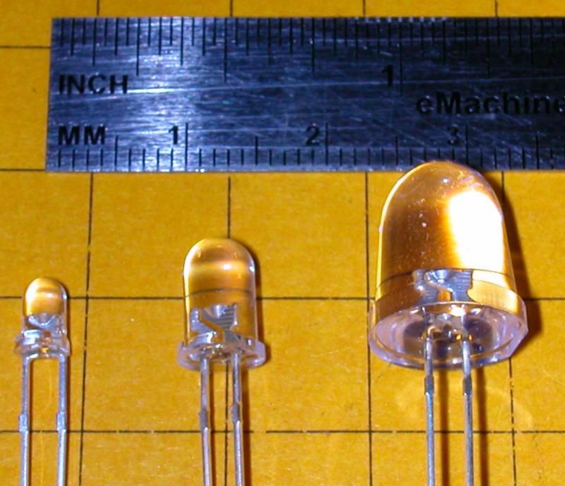
the windows. I had a number of large white LEDs that were 10 mm in
diameter rather than the 5 mm or 3mm LEDs that we use in most applications.
They had a rounded lens on the end that projected a beam of white light
ahead of the LED. My first thought was to roughen up the LED with
sandpaper to diffuse the light but that didn't give very satisfactory
results. Next I used a belt sander to completely remove and flatten the curved
end. That gave a significant improvement since the light from the LED
illuminated the flattened area causing light to reflect to the sides.
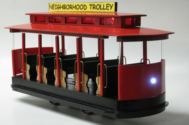
That is the way I initially modified the LEDs that I mounted in the trolley. You
can see from the photo at the beginning of the article that a good deal of
light comes from the side of each LED. It is not as diffuse as a
fluorescent bulb or a frosted incandescent bulb but is a vast improvement over focused beams.
The LEDs are mounted on the roof of the trolley by inserting each LED's leads
into two 1/16" holes in the roof. They are wired in parallel with all
cathodes wired together and all anodes wired together. The wires from
the LEDs go down a hollow post to the bottom of the trolley's base. A
current limiting resistor is in the base of the trolley.
After I completed the clerestory on the trolley I continued my experiments
with ways to diffuse LED light and came up with a method that works even
better than flattening the tops of the LEDs.
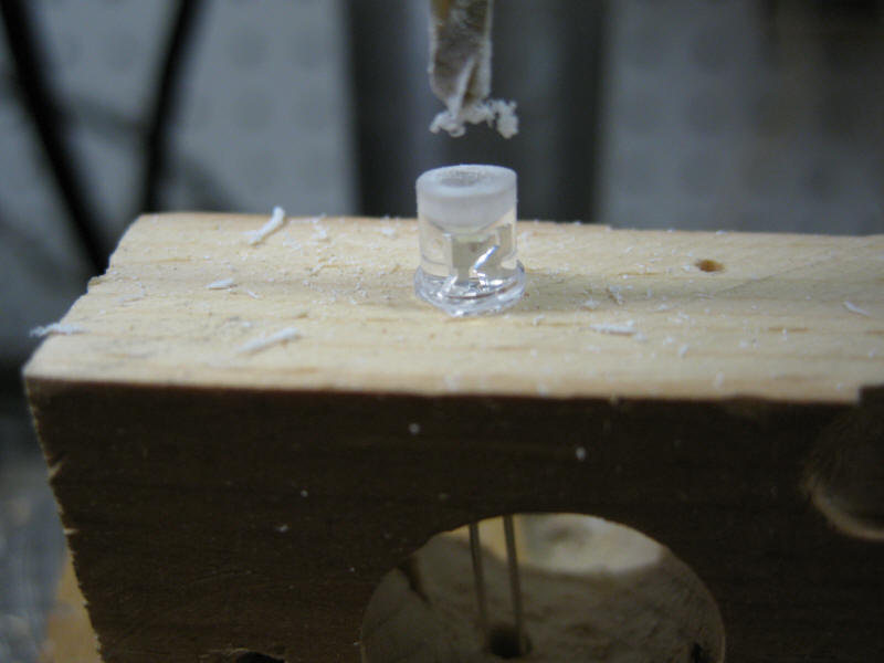
After flattening the end of a 5mm white LED I drilled a 7/64" hole in the
flattened end. This was done on a drill press with the LED sitting on
top of a scrap of wood with a hole in it to accept the LED wires. In
this photo you can see the drilled 5mm LED with its leads poking through the
hole under it.
Hold the LED in a pair of pliers and make sure that you are very careful to drill only a short distance into the plastic. If
you go too far you will hit the diode junction and destroy the LED.
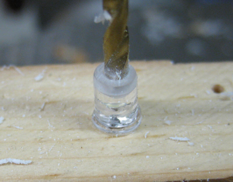
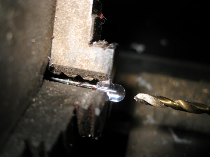
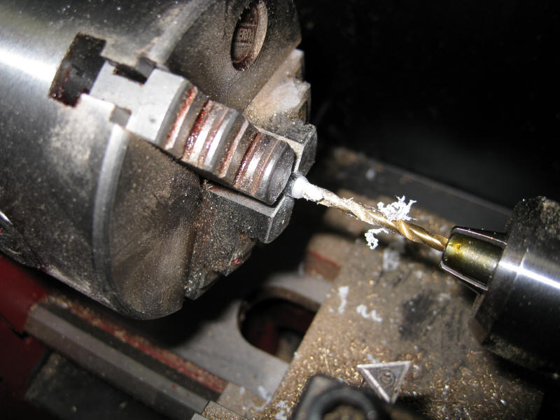
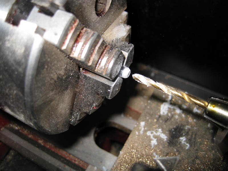
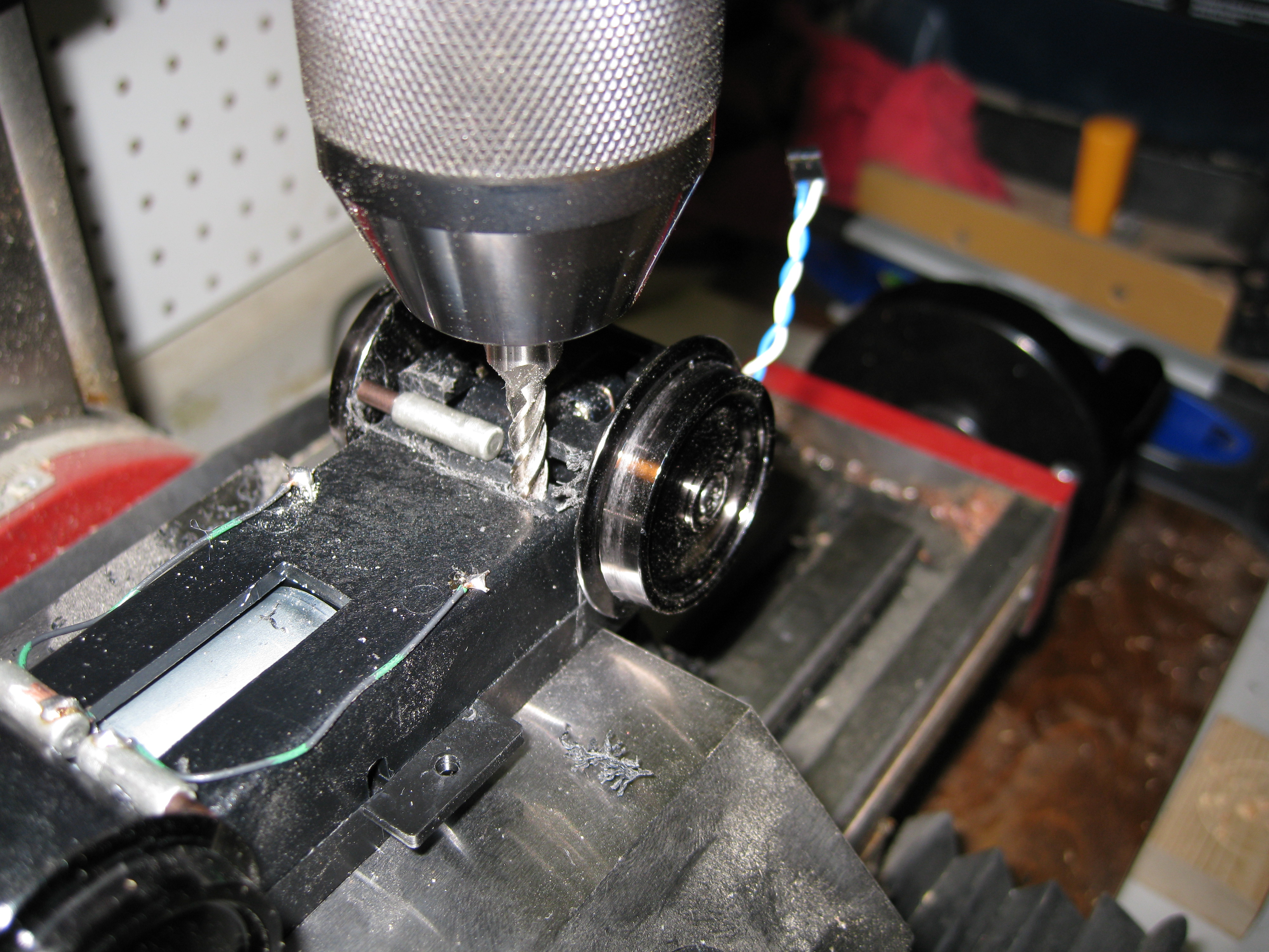
If you have access to a small lathe you can drill the holes right into the
lens of the LED. Note that the plastic collar at the base of the LED
has been removed so that it fits more squarely into the chuck.
The LED is placed in the lathe's chuck and a 1/8" bit is mounted to the tail
stock chuck.
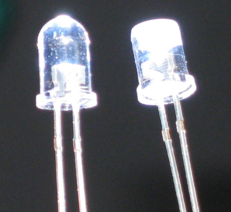
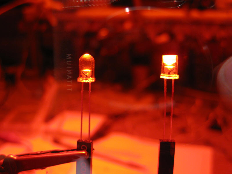
In this photo you can see the difference in brightness when viewed from the
side.
The same LEDs are shown here photographed through a red filter which makes
it easier to see the difference in brightness. You can also see the convex shape
that the drill leaves at the bottom of the hole. This acts as a
reflector that directs the light to the side.
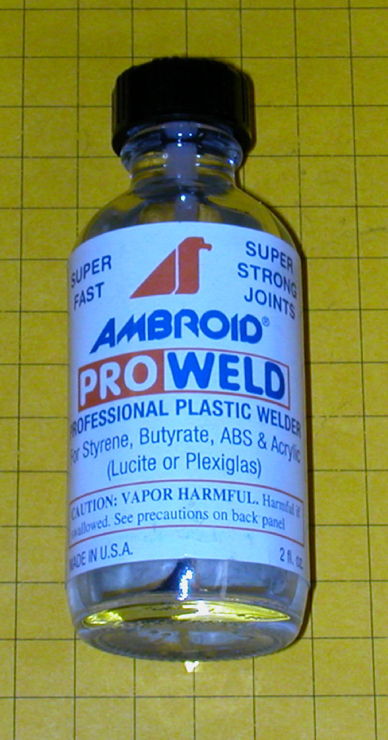
The brightness was increased a bit more by placing a drop of plastic solvent
glue (ProWeld) into the hole in the LED. This tends to soften
imperfections that are left by the drill enhancing the reflective area.
Power for the LightsOnce the clerestory wiring was extended into the base of
the trolley the next task was to get power to them. The motor, wheels
and gearing for the trolley are from an AristoCraft EggLiner. The same
power unit is used in a number of their other locomotives and it has proven
to be very robust and trouble free.
Minor rewiring was done to the unit to keep things as simple as possible
and to facilitate swapping out the whole power unit should one fail.
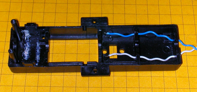
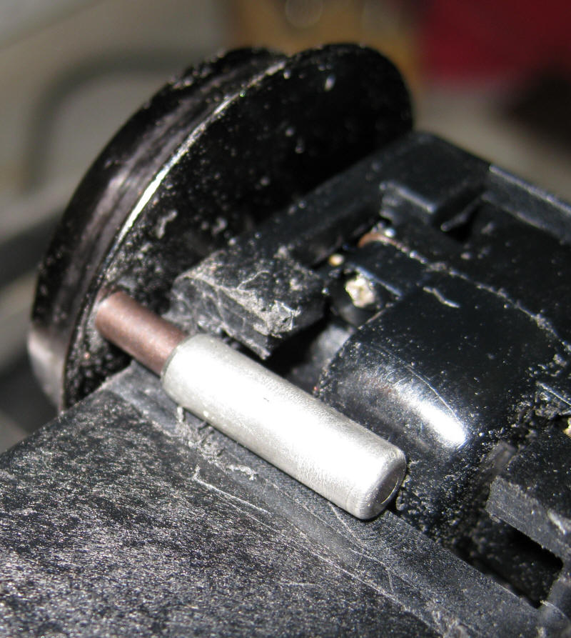
Here is the power unit from an EggLiner before modification.
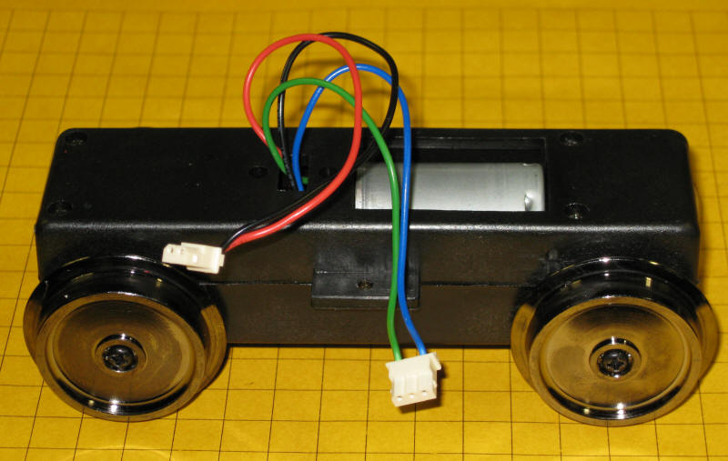
The red and black wires connect to the power pickups on the wheels and the green and
blue wires go to the motor.
The green and blue wires were cut off at the motor. The red and
black wires were shortened, stripped, tinned and soldered directly to the motor
contacts. 1/16" holes were drilled directly under the motor contacts
to allow wires to extend to the bottom of the motor block. Those holes
cannot be seen in this photo.
(Make sure you read the note at the end of this section about rotating the
motor as this is the point in the wiring where that should be done)
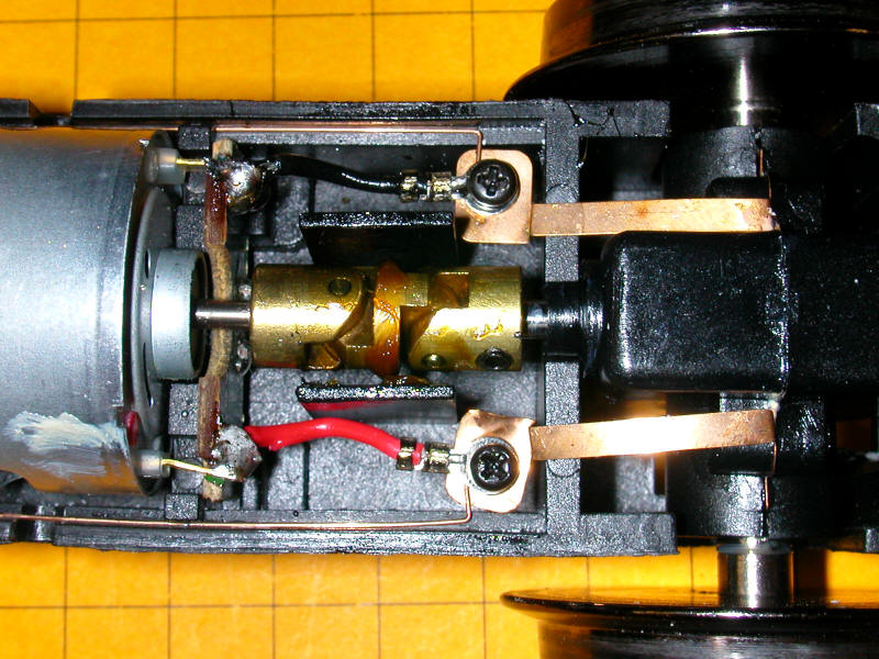
To provide access to the track power for the LEDs I drilled two 1/16" holes
in the front end of the case and ran wires through the holes from each of
the track pickups. Note that you must drill through an internal header
as well to keep the wires out of the drive mechanism.
Adding More Pickups
Many times the biggest problem with running a point-to-point trolley is
picking up power from the track. It order to improve power pickup I
added 4 LGB style spring loaded contacts to the bottom of the power unit.
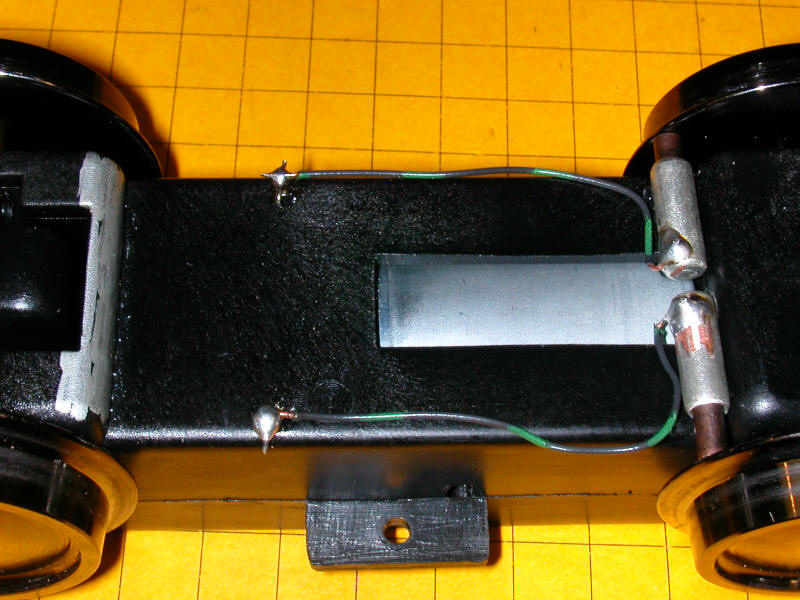
Here two pickups have been added to the right. They make good
contact with the inside of the two wheels. The electrical contacts to
the motor were extended through two small holes that you can see near the
center of the photo. The wires from the pickups are soldered to them.
A piece of the frame prevents another set of pickups from properly hitting
the sides of the wheels to the left in this photo. The area on the
left that is marked with silver paint must be removed
to let them make proper contact.
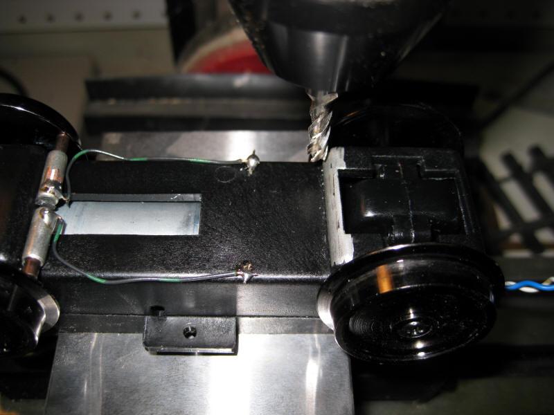
I used my milling machine to remove the excess plastic but you could do
the same with a Dremel or similar tool.
Here much of the plastic has been removed and a pickup has been inserted
to test the fit.
You can see how well the pickup mates with the inside of the wheel.
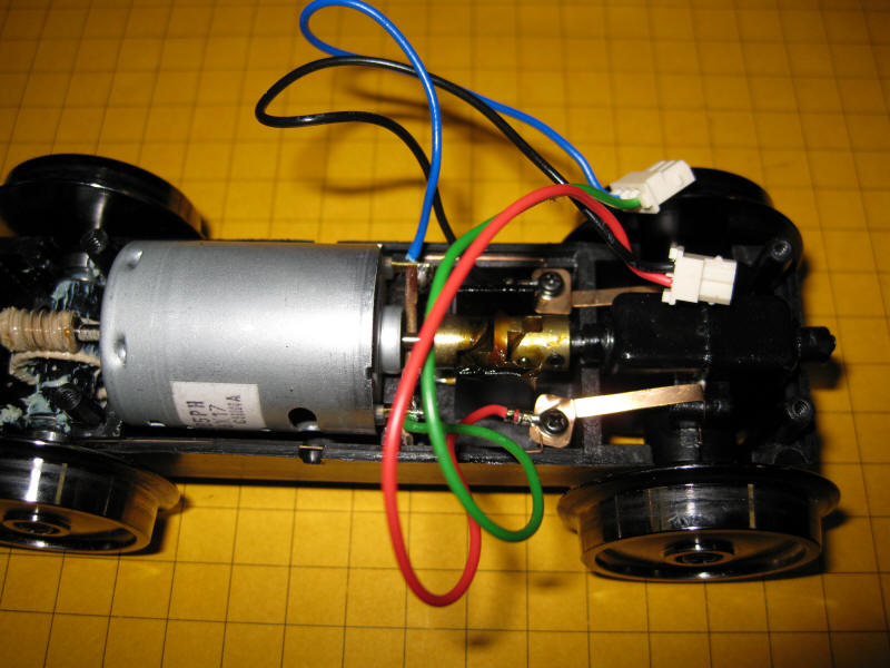
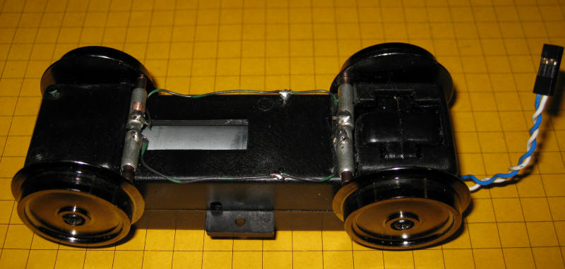
Here is the finished motor block with four additional pickups and the power
connection for lighting.
You May Have to Flip the Motor!
One word of caution. If you use the EggLiner motor block like the one
above and plan on wiring it as I did you must flip the motor so that its
terminals pick up power from the opposite terminals. The first time I
wired the power block as shown here everything worked properly but the
trolley did not stop when it came to the end of the point-to-point where a
diode is set to cut power. The direct wiring that we did does not give
standard large scale polarity related to direction of travel. Since I was
going to operate this trolley on a point-to-point that other large scale
trolleys and/or locomotives might use I opted to flip the motor rather than
change the direction of the diodes on the track. To test that you have
it wired correctly connect the negative terminal of a power supply to
one of the top pickups or wheels (with the motor block oriented as shown above) and the positive to a
lower wheel or pickup. The wheels should turn counterclockwise and the
trolley should move forward. If that is not what you get
flipping the motor is the easiest way to correct the problem.
Keeping the Lights on with SUPERCAPS!
The biggest challenge of this lighting project was to keep the LEDs in
the clerestory and at the front or back of the trolley lit even when power
was removed from the track at each end of the point-to-point. I knew
that a capacitor had the ability to do this since I had used them in the
first Children's Hospital layout that we worked on some years ago.
(see:
Give Your Engines the Capacity to Ignore Dirty Track)
The problem with the capacitors that I used in that application was their
size. The smaller ones were over 4" tall and nearly 2" in diameter.
The Mr. Rogers trolley had no where near that much space under the frame.
Fortunately a new generation of capacitors, called Supercaps, provides
another alternative. Super capacitors, sometimes called ultra caps or
supercaps, are a relatively new development. They behave much like normal
capacitors but have much more storage capacity. For more information on
the technology behind them have a look at this link:
http://en.wikipedia.org/wiki/Supercapacitor. There you will learn about a
wide range of things for which they are being used, including an
experimental city bus that runs on them and gets recharged at every stop.
There is also a portable electric drill that operates from a supercap, see:
http://www.colemanflashcellscrewdriver.com/ . I am sure that we
will see these intriguing devices used in more and more applications in the
next few years.
In order to increase the voltage that they supply, which is typically
only a few volts, super caps are frequently wired in series. This increases
the voltage while the capacitance decreases. The supercaps that I have
been experimenting have a rating of 10 farads at 2.3 volts. That is
not enough voltage for our LEDs but putting two in series gives 4.6 volts, more than
what we need.
The circuit below utilizes the following readily available components:
- a bridge rectifier (D1) to give consistent polarity from varying
track polarity
- a capacitor between the bridge rectifier and the voltage regulator
to protect the latter from "noisy" DC (optional)
- a 7805 voltage regulator to supply 5 volts from varying track
voltage
- two super caps (C1 & C2) to store power
- five LEDs (D2-D6) with 470 ohm current limiting resistors (R1-R5)
- a diode (D7) to drop the voltage that goes to the caps from 5 to a
bit below their 4.6 volt maximum. Use a 1N5408 (rated @ 3 amps) -if you
use another diode check it to confirm a 0.7 volt drop.
The bridge rectifier (D1) converts DC of varying polarity to a consistent
polarity. The voltage is dropped to 5 volts by the LM7805 voltage regulator.
The output voltage is still a bit above the 4.6 volt maximum that our two
capacitors can handle so diode D7 (a 1N5408) is inserted between the output of the
regulator and the rest of the circuit. You will recall that a series diode
drops a DC voltage about 0.7 volts so we can be sure that we are not putting
an excessive voltage into the capacitors. The five LEDs (D2-D6) are wired in
parallel with the two capacitors. Note that there is a resistor (R1-R5) in
series with each LED to limit the current that the LED can draw.
When power is applied to the track the capacitors will take a few seconds
to charge. Once they come up to voltage this circuit will keep the LEDs lit
brightly for well over 5 minutes each time the train is stopped. Depending
on the types of LEDs you use they can remain illuminated to some extent for
well over 15 minutes. The time that you will see light from LEDs also varies
based on their color. White LEDs take a higher voltage, usually in the
neighborhood of 3 volts, to give any light at all while amber, red and other
colors take only a volt or so to light. I have had amber and green LEDs stay
illuminated for 45 minutes with just the two super caps shown here.
The trolley will be controlled by my BARC (Blinking Auto Reverse
Controller) which can easily be set to reverse the trolley before the lights
in the clerestory completely extinguish. I have found that it is best
to get the trolley moving again before the supercaps completely discharge as
the voltage regulator has to handle a brief 2 amp surge when they are
completely discharged.
Front & Rear Directional Lighting
The lights at either end of the trolley presented a few additional
challenges. The first was selecting LEDs. I wanted them to be
very bright since some of the trolley's operation would take place in a
lighted room at the hospital and I didn't want them to be overpowered by the
room lights. More importantly I wanted lights that looked good.
The typical 5mm bullet shaped LEDs are fairly long and would project farther out of the trolley
than I wanted. The end plates on the trolley were made from shaped
3/32" Plexiglas and I didn't want an LED sticking very far out of the front or
back of the plastic. In this case another new product filled
the bill. In order to achieve greater brightness some manufacturers
have started to put multiple LED junctions in one case. These are
called multi-chip LEDs. The total light output from the three LEDs on
the chip is blinding.
This photo of a multi-chip LED was taken through a filter and with the
voltage way below what the LED needs to operate. If you look carefully
you can make out the three separate diode junctions and the wires that
connect to them.
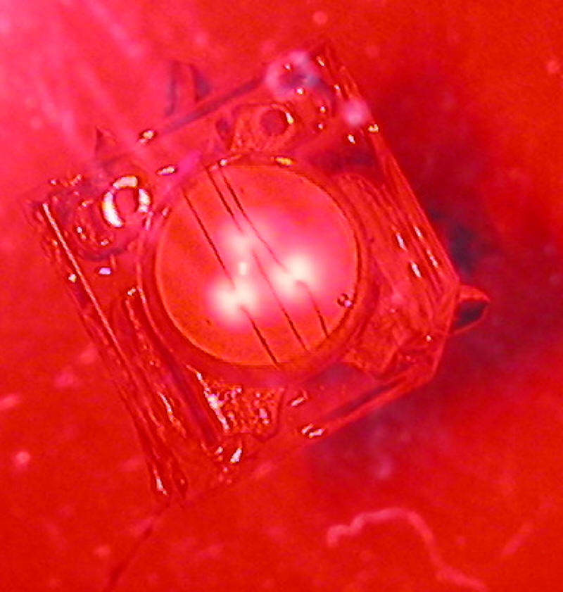
They can be extremely bright and come in a number of
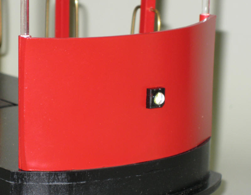
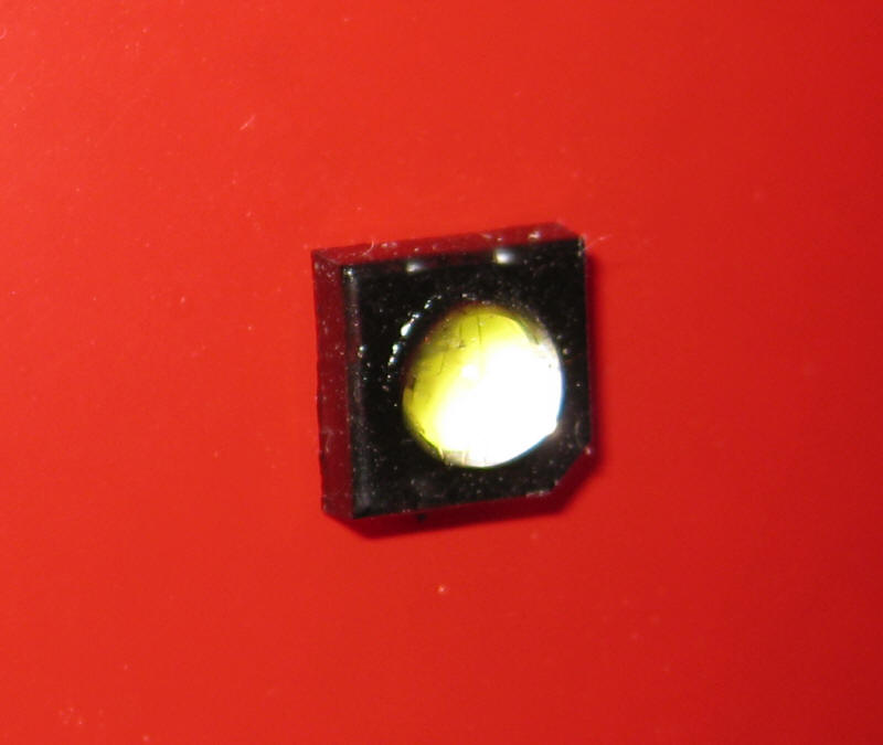
case configurations. The ones that I chose were ideal for this
application since the LED has a square base and a small 5mm lens that barely
sticks out above the base.
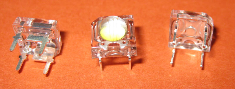
These LEDs have four leads coming out of the back. The leads are
wired in pairs with the two smaller leads being anodes and the two larger
leads being cathodes. Even though you only need to hook up one of each
lead the fact that there were four leads really helped in mounting them to
the plastic. I just drilled four holes, inserted the LED's leads and
bent them over to secure the LED. I just had to make sure that I
joined the two cathodes and the two anodes together before a drop of solder
made them a permanent part of the trolley.
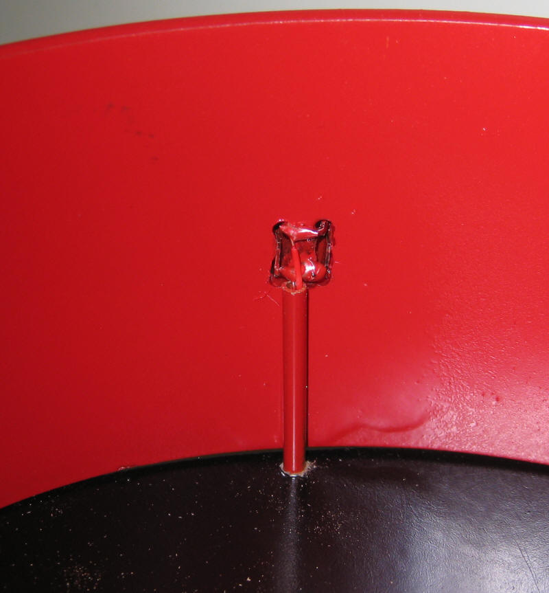
Thin (30 gauge) wire was soldered to the LEDs and routed through the
trolley's base via a 1/16" piece of brass tubing. I also painted
the square base of the LEDs black to make it look like a housing.
Directional Lighting Circuit
The circuit that controls the front and rear lights is a bit more complex
but starts out with virtually the same components that we used on the
clerestory. If we were satisfied with having both lights stay on
whenever the trolley ran we could have just wired these LEDs in parallel
with the clerestory lights and we would have been done.
I wanted to have directional lights that would have only
the front light illuminated when the trolley was going forwards and only the
rear light lit when it went the other way. This would accomplish two
things. First it would look better as there is little sense in
lighting the track behind you. More importantly it would preserve the
power in the capacitors so that the lights would be able to stay on longer
when at the end of the track. I also wanted a circuit that would
utilize only one additional set of supercaps as they are fairly large and space was at a premium under
the trolley.
The circuit adds a few components to what we used for the clerestory
lighting. LEDs D3 and D4 are at opposite ends of the trolley. R1
and R2 are 30 ohm current limiting resistors that keep too much current from
destroying the LEDs. The components that actually turn the appropriate
LED on or off are D5, D6, R5, R6, Q1 and Q2. When the polarity on the
track is set one way one of the diodes conducts turning on the transistor it
is attached to. When the polarity reverses the other diode comes into
play. The transistors that I used are a special type of transistor
called Mosfets (metal oxide silicon field effect transistors). The
work just like regular transistors but have one characteristic that makes
them very useful in this application. I'll explain more about that in
a moment.
We want one of the transistors to turn on when the trolley goes one way
and the other when it reverses. That is taken care of with D5
and D6. But we also want that transistor to remain on once the trolley
gets to the end of the track where it completely loses power until the
polarity is reversed by the BARC controller. Here is where capacitors
C3 and C4 and resistors R3 and R4 come in. When one of the transistors is first
turned on the capacitor connected to its base (note that the base is called
a gate on a Mosfet) charges. When the trolley ends its run the charged
capacitor keeps the transistor "on" for a time even though track power is
gone. The resistor that is paired with the capacitor slowly discharges
the capacitor so that the LED goes out after a few minutes.
Remember that we don't want to completely discharge the supercaps if we can
help it.
The last two components, R7 and R8 , keep both the lights from being on
at the same time. When LED D4, for example, is on R8 is connected to
ground and discharges capacitor C4 in a second or two extinguishing the LED. Similarly R7
will discharge capacitor C3.
The amount of time that the LEDs stay on after the trolley has gotten to
the end can be adjusted by changing resistors R4 and R3. Larger
resistors discharge C3 and C4 more slowly leaving the lights on longer.
Smaller value resistors discharge the capacitors more quickly.
To review, when D5 conducts it turns on transistor Q2. Capacitor C3
also charges. When the trolley hits the end of the track D5 no longer
supplies power to the transistor and it would go off extinguishing LED D4.
This does not happen because of the charge on C3 which keeps the transistor
on.C3 slowly loses its charge through R4 eventually turning Q2 off.
If C3 is not fully discharged when the trolley reverses resistor R7 will
quickly discharge C3 as soon as Q1 is turned on.
Now to the reason for the Mosfet transistors. When I first built up
this circuit I used standard 2N2222 transistors to turn the LEDs on or off.
Everything worked fine, but the LEDs only stayed on for a short time (1 or 2
seconds) after the track power was lost. It seemed that C3 or C4 were
discharging very quickly. I tried larger capacitors but that only
helped a bit. I did some research and found that regular NPN
transistors like the 2N2222 draw a good bit of current through their base
lead. That is what was discharging the capacitor. It was losing
its charge through the transistor. Some more research led to the use
of Mosfets which draw virtually no current through their gate lead.
Problem solved!
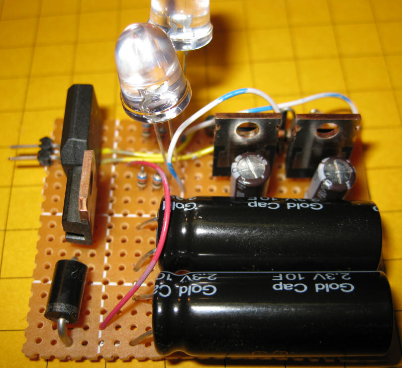
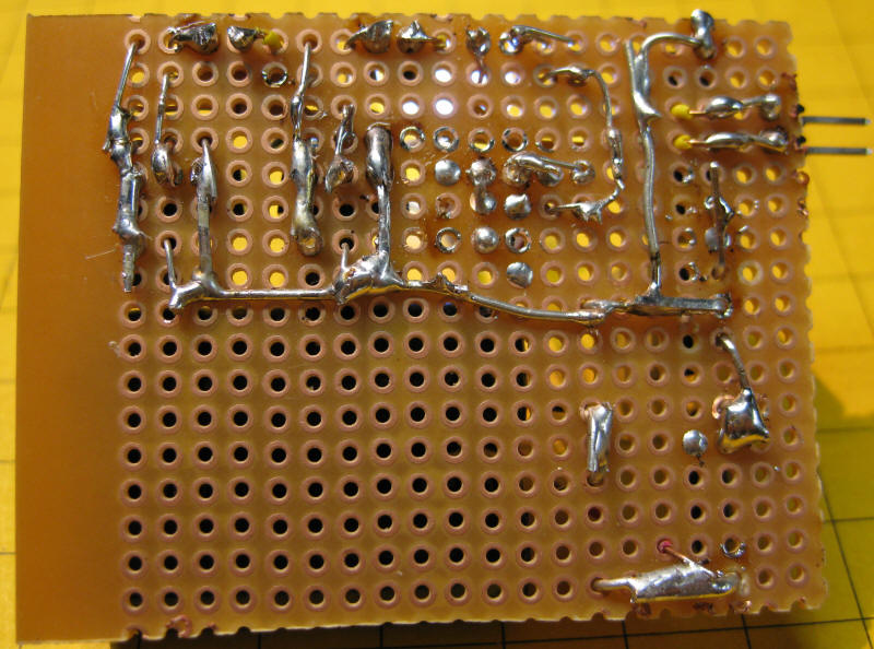
The prototype circuit was built on a small piece of circuit board. The
two supercaps are the large black objects at the bottom. The bridge
rectifier is in the upper left, below it is the voltage regulator and diode D2.
In the upper right are the two Mosfets. Behind them are capacitors C3 &
C4. Two 10mm LEDs were temporarily installed for testing.
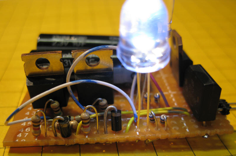
When viewed from this angle you can see the Mosfets more clearly as well as a
number of resistors and diodes. The pairs of small resistors in the bottom
right are 60 ohms each. They are wired in parallel to give me two 30 ohm
current limiting resistors for the LEDs.
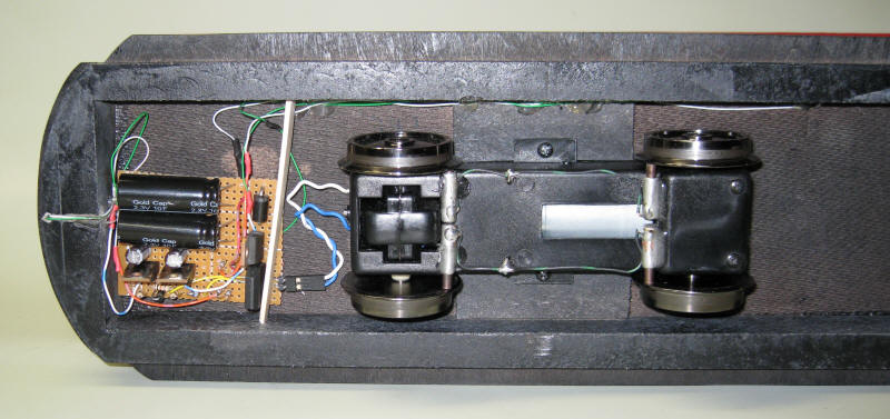
Here the board has been installed under the trolley.
In operation the trolley's forward facing headlight and clerestory lights
come on when the BARC applies power to the track. When the trolley gets to
the end and hits the section of track with a diode in it the trolley stops but
the clerestory lights and the forward facing light stays on. If the
trolley stays at the end for more than 2 minutes the head light goes off.
If it reverses before that time elapses the other head light goes on and the
first one goes out in a second or two. I think you will agree that the
lighting is more prototypical and more interesting to watch!
Even though the project described here is designed for a point-to-point route
the same concepts and the circuit from the clerestory can be used on any
locomotive or piece of rolling stock where you want lights to remain on even
after track power has been removed.
I hope you learned something from this discussion and the circuits that are
described. I can assure you that I learned a great deal in the process of
designing it!
If you have difficulty locating any of the items described in this article
please contact me as I have a number of them on hand. (email:
dave@davebodnar.com )