| Thanks to Steve Lowry (UK Steve on
TrainBoard) for the following
procedure! These notes should get you to the point where you can program the ESP8266.
For the ESP8266
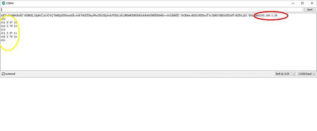
This image shows the info from the Command Line in Windows as I went through the steps above.
|
Steve's code for the ESP8266 //*** IMPORTANT *** Most of the libraries used are included in the ESP8266 Core package which you must install to the Arduino IDE for this sketch to compile.
//Please use the Git method here https://github.com/esp8266/Arduino and NOT the File > Preferences > Additional Boards Manager URL.
//WebSocketsServer.h appears to be broken using the later. And DO include the Python requirement (correct at Feb 15 2016) The author is aware of this issue.
//You will need to install Git to simplify that operation.
//If the sketch compiles OK but won't upload properly, then go Sketch > Export compiled Binary. A .bin file will be created in this sketch's folder.
//Then upload the binary with your favorite flashing tool.
//Please remember to fill in your home network SSID and PASSWORD. In this version when you reboot your esp8266 it will automatically log on to your WLAN.
//Make a note of the IP address assigned by your router by logging on to its home page. Your PC or Mobile also need to be on this same network.
//With the "Webpage" open on your chosen device, type the IP and Port in the following format eg. 192.168.11.55:81 (port == @line 28) press Enter(desktop)
//or tap the screen outside the box (mobile).
//With luck you are now connected enjoy. A message will confirm in later versions.
//Console Debugging is available in Chrome windows desktop for the html wireless side. And at the other end (Arduino) a serial monitor will let you know
// whats happening there.
//You can also see serial out from esp8266 if you connect by usb and use a serial monitor there. (Debug from this sketch shows up there)
//In tests I hooked up 2 seperate clients at the same time so multi-client is confirmed. However as certain values are fixed assignment things start to
//go wrong quickly. We can work that out ;)
//There is room for many more functions on the page, this is just Proof of Concept.
//Special thanks to Rahul 27 who created the original sketch on which this sketch is based. And also Markus Sattler for the WebSocketsServer library.
//This software is Free. Enjoy. Steve Lowry(indev2)2016.
#include <Arduino.h>
#include <ESP8266WiFi.h>
#include <WebSocketsServer.h>
#include <Hash.h>
#include <EEPROM.h>
WebSocketsServer webSocket = WebSocketsServer(81);
String c;
String d;
int cInt;
int dInt;
const char* ssid = "YOUR SSID";
const char* password = "YOUR PASSWORD";
const int redPin = 15; //Debug LED function not needed ***All debug lines can be deleted once you understand the code and you have it working, we like tidy code ;)***
const int greenPin = 12; //Debug LED function not needed
void webSocketEvent(uint8_t num, WStype_t type, uint8_t * payload, size_t lenght) {
switch (type) {
case WStype_DISCONNECTED:
break;
case WStype_CONNECTED:
{
IPAddress ip = webSocket.remoteIP(num);
}
break;
case WStype_TEXT:
{
String text = String((char *) &payload[0]);
if (text == "PON") {
digitalWrite(12, HIGH);//Visual Debug - Green LED will come on at Power ON
digitalWrite(15, LOW);//Debug - not needed
Serial.println("<1>");
}
if (text.startsWith("CAB1")) {
String c = (text.substring(text.indexOf("CAB1") + 4, text.length()));
int cInt = c.toInt();
EEPROM.write (4, cInt);
EEPROM.commit();
delay (20);
Serial.print("Cab# Entered t1 ");//Debug
Serial.println(cInt);//Debug
}
if (text.startsWith("CAB2")) {
String c = (text.substring(text.indexOf("CAB2") + 4, text.length()));
int cInt = c.toInt();
EEPROM.write (12, cInt);
EEPROM.commit();
delay (20);
Serial.print("Cab# Entered t2 ");//Debug
Serial.println(cInt);//Debug
}
if (text == "FOR1") {
dInt = (1);
EEPROM.write (0, dInt);
EEPROM.commit();
int Cab1 = EEPROM.read(4);
Serial.print("Forward Entered t1 ");//Debug
Serial.println(dInt);//Debug
Serial.print("<t1 ");
Serial.print(Cab1);
Serial.println(" 0 1>");//Stops train (if not stopped) on direction change
delay (20);
}
if (text == "FOR2") {
dInt = (1);
EEPROM.write (8, dInt);
EEPROM.commit();
int Cab2 = EEPROM.read(12);
Serial.print("Forward Entered t2 ");//Debug
Serial.println(dInt);//Debug
Serial.print("<t2 ");
Serial.print(Cab2);
Serial.println(" 0 1>");
delay (20);
}
if (text == "REV1") {
dInt = (0);
EEPROM.write (0, dInt);
EEPROM.commit();
int Cab1 = EEPROM.read(4);
Serial.print("Reverse Entered t1 ");//Debug
Serial.println(dInt);//Debug
Serial.print("<t1 ");
Serial.print(Cab1);
Serial.println(" 0 0>");
delay (20);
}
if (text == "REV2") {
dInt = (0);
EEPROM.write (8, dInt);
EEPROM.commit();
int Cab2 = EEPROM.read(12);
Serial.print("Reverse Entered t2 ");//Debug
Serial.println(dInt);//Debug
Serial.print("<t2 ");
Serial.print(Cab2);
Serial.println(" 0 1>");
delay (20);
}
if (text.startsWith("x")) {
String xVal = (text.substring(text.indexOf("x") + 1, text.length()));
int xInt = xVal.toInt();
analogWrite(greenPin, xInt); //Debug - not needed, Green "ON" LED will brighten/dim according to throttle up/down
int dvalue = EEPROM.read(0);
int cvalue = EEPROM.read(4);
Serial.print("<t1 ");
Serial.print(cvalue);
Serial.print(" ");
Serial.print(xInt);
Serial.print(" ");
Serial.print(dvalue);
Serial.println(">");
}
if (text.startsWith("y")) {
String yVal = (text.substring(text.indexOf("y") + 1, text.length()));
int yInt = yVal.toInt();
int dvalue = EEPROM.read(8);
int cvalue = EEPROM.read(12);
Serial.print("<t2 ");
Serial.print(cvalue);
Serial.print(" ");
Serial.print(yInt);
Serial.print(" ");
Serial.print(dvalue);
Serial.println(">");
}
if (text == "RESET") {
EEPROM.write (0, 0);
EEPROM.write (4, 0);
EEPROM.write (8, 0);
EEPROM.write (12, 0);
EEPROM.commit (); //All stored values set zero
delay (20);
digitalWrite(15, HIGH);//Visual Debug - not needed - Red LED will come on at Power OFF
analogWrite(greenPin, 0); //LED function - not needed
Serial.println("<0>");
}
break;
}
webSocket.sendTXT(num, payload, lenght);
webSocket.broadcastTXT(payload, lenght);
break;
case WStype_BIN:
hexdump(payload, lenght);
// echo data back to browser
webSocket.sendBIN(num, payload, lenght);
break;
}
}
void setup() {
Serial.begin(115200);
pinMode(15, OUTPUT);
pinMode(12, OUTPUT);
EEPROM.begin(512);
WiFi.begin(ssid, password);
while (WiFi.status() != WL_CONNECTED) {
delay(100);
}
Serial.println(WiFi.localIP());
webSocket.begin();
webSocket.onEvent(webSocketEvent);
}
void loop() {
webSocket.loop();
}
|
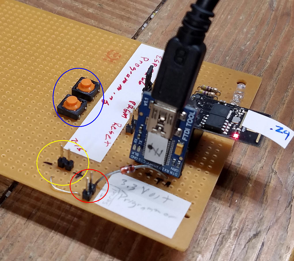
| Programming the ESP8266 I built up this board to program the ESP8266 - the USB to serial adapter is set to 3.3 volts and supplies power to the circuit. The reset and program buttons are circled in blue, the power in buttons are circled in yellow and the serial out (to the DCC++ board) are circled in red. Note that there is a diode in series with the TX out pin.
Note that the IP address that the ESP8266 gets from the router appears in the terminal window when it is reset, circled in red. The commands that it receives are shown in the terminal as well (circled in yellow)
|
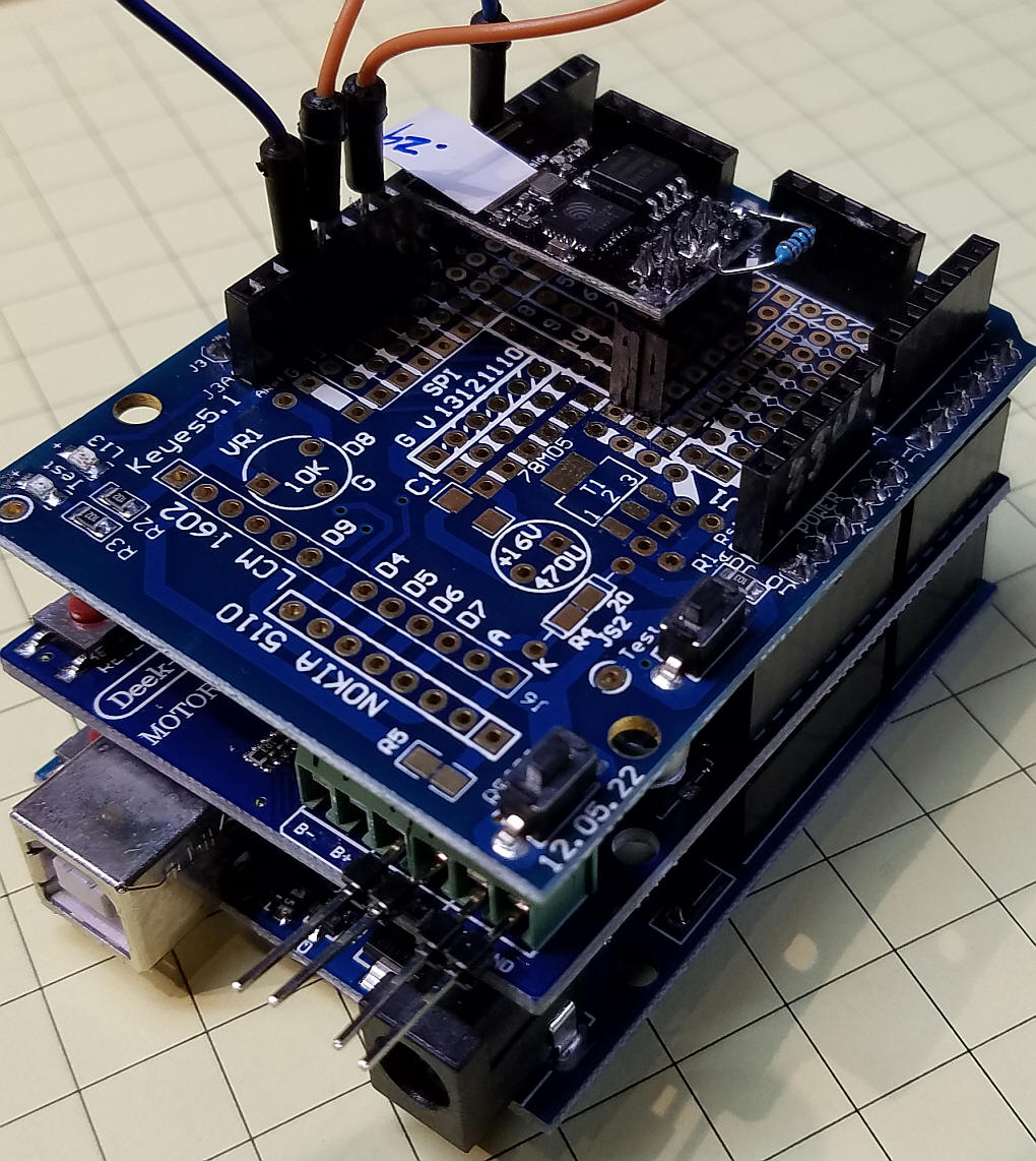
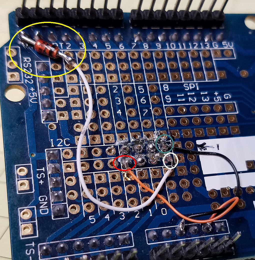
| Shield
for the ESP8266 To facilitate testing I added a shield to the stack (Arduino + Motor Shield) of boards that houses the ESP8266. It only requires 3 connections to the shield.
All wiring was done on the bottom of the shield. Please note that many shields, including this one, have hard-to-see connections between pads. I ran a Dremel cutting wheel down the row of pads that I used, both sides, to cut any connections - I then tested the adjoining pads to make sure there were no shorts between then. The black wire goes from ground on the shield to the pin circled in black. The orange wire goes from the 3.3 volt power pin on the shield to the pin circled in red. The TX pin (circled in white) goes to the RX pin on the Arduino via a small diode. Note that the ring on the diode goes towards the ESP8266. |