|
Initial setup At first the PICAXE and XBee would not talk. I had to make the following changes to get things to work:
|
| Screen Shot #1
Screen Shot #2
|
Symbol SerSend = b.4 'pin 9 Symbol temp = b1 Start: temp = temp + 1 serout SerSend, N2400, ("temp= ", #temp, 13,10)
'serout SerSend, T2400,
("temp= ", #temp, 13,10)' use this if on 3.3 volts / no MAX3232 |
| Screen Shot #3
|
| This photo shows the Spark Fun USB XBee board (see:
https://www.sparkfun.com/products/8687 ) - a reset button has
been added by connecting the RST pin and ground pin to a NO
momentary switch. This unit is connected to a PC running the
X-CTU program in terminal mode.
|
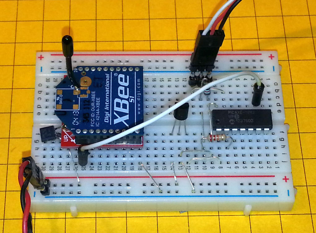
| This is the transmitting unit. A PICAXE 14M2 in installed
on a D-Axe board (on the right) - see:
http://www.aztecmcu.com/catalog/i19.html The XBee is on the left mounted to a prototype board using another Spark Fun board - see: https://www.sparkfun.com/products/8276 -A 3.3 volt regulator has been added to that board so that 5 or more volts can be used to power the circuit. The device between the two is a MAX3232 board that is described in detail here: http://trainelectronics.com/RaspberryPi/#Connecting_to_the_built-in_RS-232_Port_with_a_MAX3232 The wires at the top go to the programmer, those in the lower left and lower right supply power to the two boards.
|
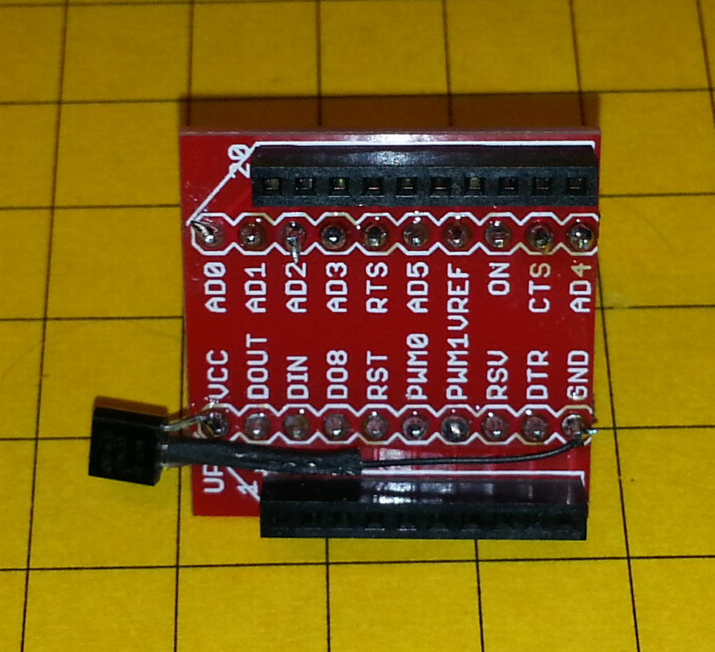
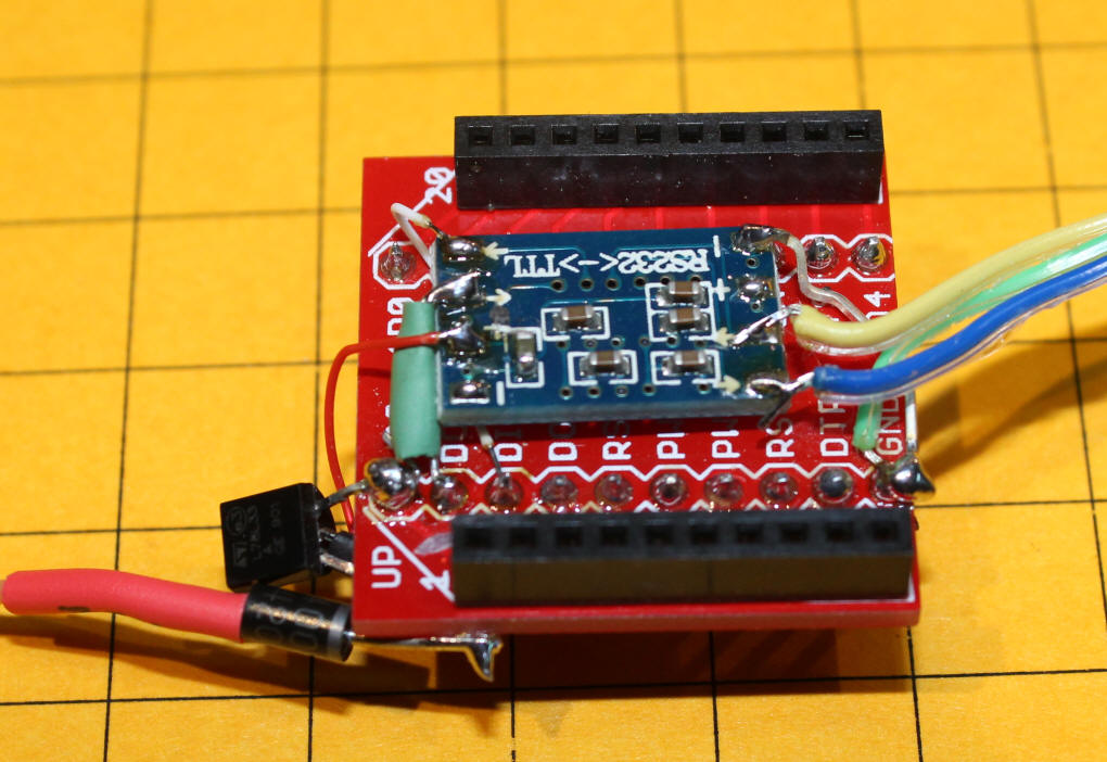
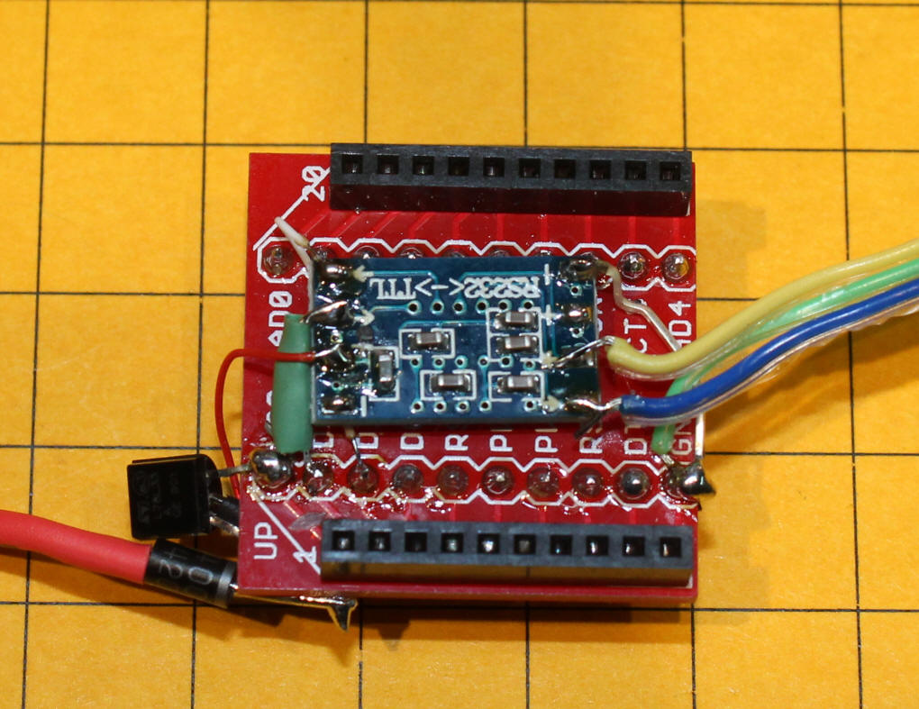
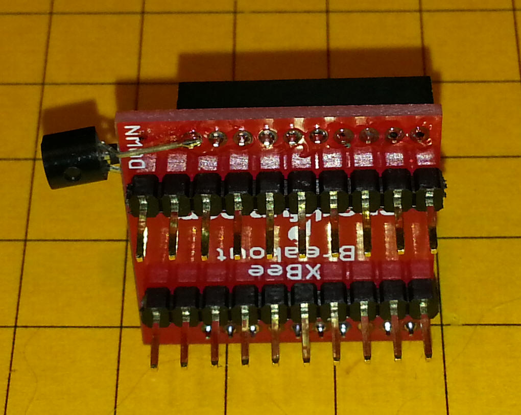
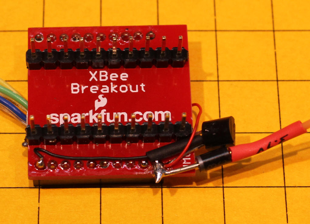
| These photos show the addition of the 3.3 volt regulator to the
Spark Fun breakout board.
|
 |
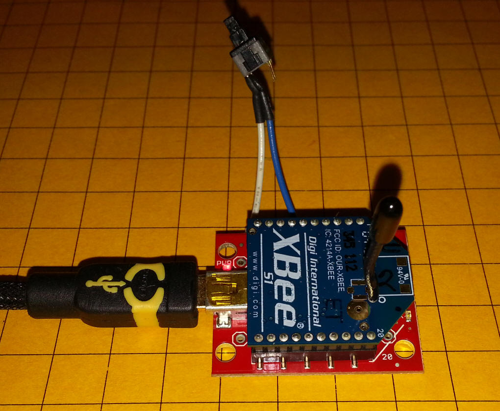
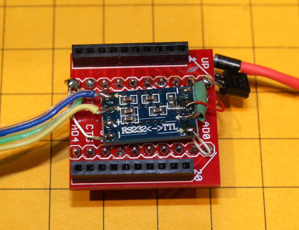
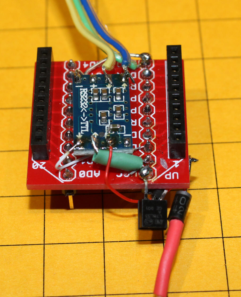
| Rather than use the MAX3232 to make sure that a 5 volt
microcontroller pin connects to the 3.3 volt XBee you can (if your
microcontroller will work on 3.3 volts) operate everything from a
3.3 volt supply as shown here. The PICAXE on the right is a
14M2 which will operate down to as few as 3 volts. It is
connected directly to the digital input pin on the XBee. The
programming cable in the upper right is for the PICAXE.
|
| The PICAXE shown above can be swapped out for a PIC16F684 using the program shown below. Note that this program sends data at 9600 baud so that the speed settings on both XBees can be left t otheir default settings rather than switching from 9600 to 2400 baud. |
| Include "modedefs.bas" ansel = 0 cmcon0 = 7 Serial_out var gpio.0 'pin 7 Temp1 var word Serout serial_out,t9600,[13,10,"d. bodnar Ver 1.0",13,10] Serout serial_out,t9600,[13,10,"09-30-13",13,10] Serout serial_out,t9600,[13,10,"XBee test @ 9600 baud",13,10] pause 1000 gpio = %00000000 '3 & 4 inputs - others outputs temp1=0 top: serout serial_out,t9600,["Temp1 = ",#temp1 , 10,13] temp1=temp1+1 goto top: |
| XBee to XBee Serial using PICAXE & PIC |
|
This program for the PICAXE sends data to the XBee
'd, bodnar 10-7-13 working to send to XBee
via serial
This program for the PIC receives data from the XBee and displays it on the terminal 'd. bodnar 10-7-13 |
|
|
|