Dual Coil Relay Once Around
d. bodnar
revised 12-31-10
Be sure to check the Addendum that discusses an alternative circuit
When we set up a train layout at a public event or around the Christmas tree we may not want the train to run continuously but only when someone is there to enjoy it. These simple circuits activate a train on a loop of track so that it goes around once each time a button is pressed and always returns to the starting point where it waits patiently until the button is pressed again.
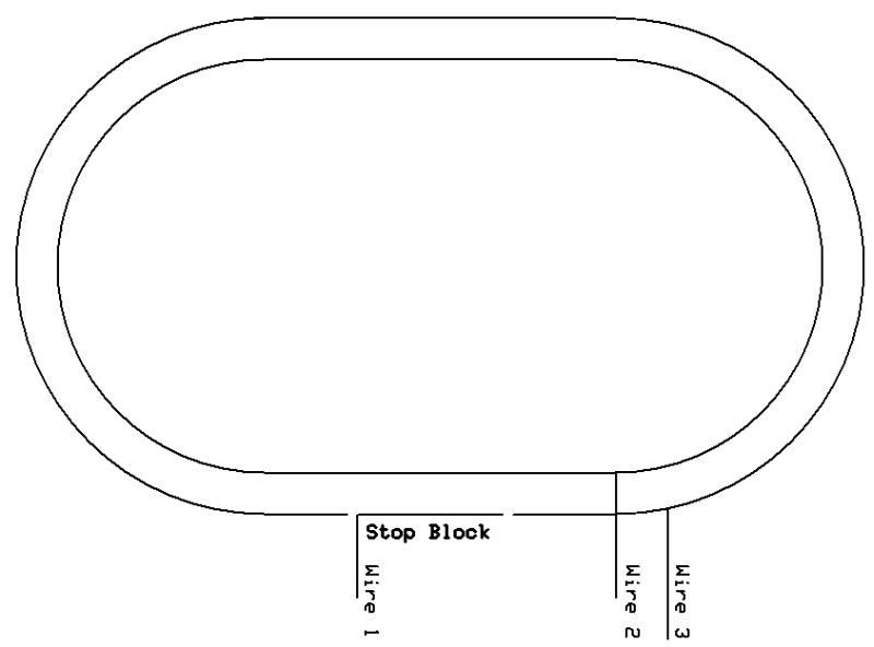
Track Preparation
For simplicity's sake let's work with a basic oval of track with a short insulated section where we want the train to stop and wait. We'll call this the stop block. Note that in the stop block only one rail of the track is not connected to the main loop. It is not necessary to isolate both rails.
Power for the main loop of track goes to Wire 2 and Wire 3. To activate the stop block the power that goes to Wire 3 also needs to go to Wire 1. If power is removed from Wire 1 the train will stop in the stop block.
Circuit #1 - A Single Push Button Switch
The simplest way to get the train out of the stop block is to wire the track
as shown here.
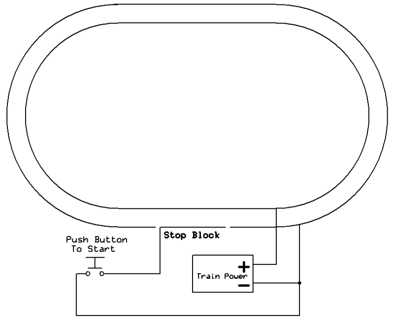
Train power is always connected to the main loop. The stop block is normally unpowered. When a train is in the stop block pushing the button will apply power to the stop block and the train will move. The only disadvantage to this circuit is that you must HOLD the button until the train exits the stop block. If you only push it for a moment the train may not move enough to pick up power beyond the insulated track.
Circuit #2 - Dual Coil Latching Relay
This circuit uses a single dual coil latching relay and a single reed
switch to animate the train. You may recall that dual coil latching relays were
used to perform some normally challenging tasks in another of my articles,
Controlling Reverse Loops & Wyes - Dual Coil Relays to the Rescue!
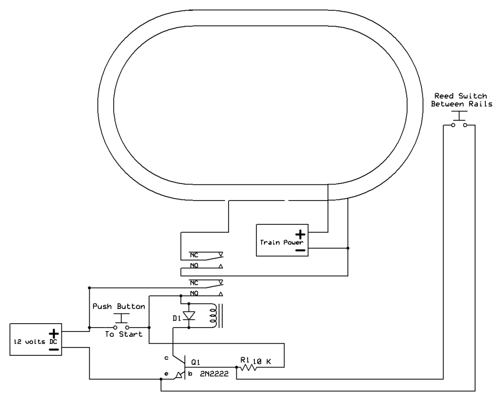
Here one of the relay's coils is connected to a push button switch and the other
coil is connected to a reed switch that lies between the rails. When the
start button is pressed power is supplied to the stop block and the train starts
out. When the train passes over the reed switch a magnet that is glued to
the bottom of its frame activates the reed switch and toggles the relay so that
the stop block's power is removed. When the train reaches the stop block
it stops. Only a brief push of the start button is necessary to apply
power to the stop block. (For more information on reed switches and relays
see:
Garden Railway Sensors Part I )
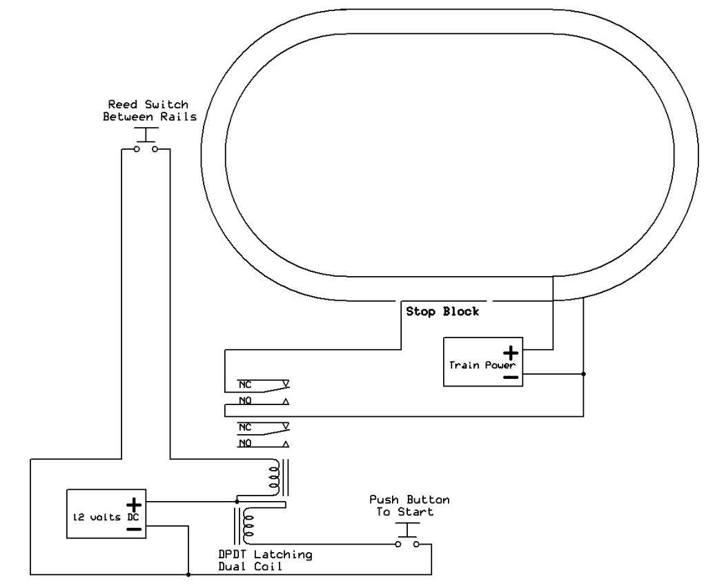
The Dual Coil Latching Relay Diagram shows how it is set up and wired. Dual coil relays are available from a number of vendors including the following:
eBay - item
Latching Relay Dual Coil 12 Volt
Digikey - item
# PB1085-ND
Mouser - item #
655-V23079B1203B301
Even though these relays are physically small many of them can easily handle 3
to 5 amps and are quite capable of operating many of our large scale trains. If you need
to control a larger train you can just use the latching relay to activate a relay with a higher amperage rating and connect that relay to the
stop block.
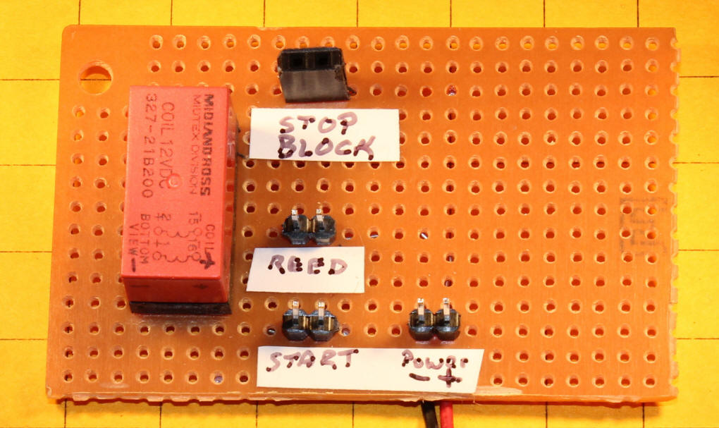
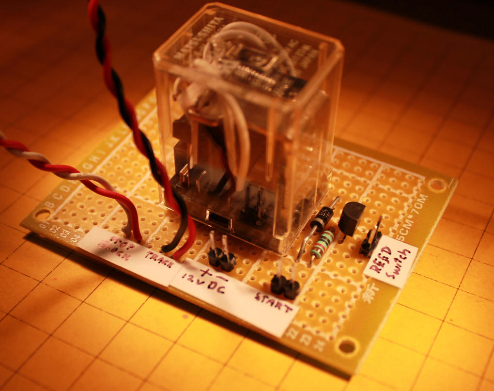
This photo shows my prototype circuit using a DPDT Latching Dual Coil relay. This relay is a 12 volt unit. Each of the connections that go to the switches and track are labeled. This latching relay is polarity sensitive, as are many others, so it is important that the positive and negative connections are made correctly.
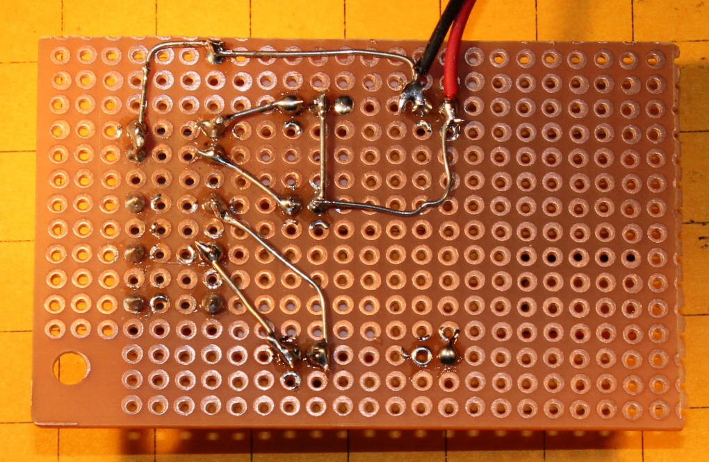
Back of board.
As noted earlier one advantage of using the relay and reed switch is that only a brief button push is needed to get the train out of the stop block. A more significant advantage comes into play if you have a more complex layout. Most latching relays are DPDT (double pole, double throw) as is the one shown in the diagram. There is an unused set of contacts on our relay and we can use it to do some interesting things.
If you have, for example, another loop of track that either crosses the first loop or shares track with it via switches the unused relay contacts can be used to cut power to the other train so that is does not cross the track when the first train is active. These contacts could also be used to activate an accessory (lights, sound, etc. ) when the train is running.
Circuit #3 - Modifying a DPDT Relay to Make it Latch
If you would like to try using a circuit that is centered around a more standard DPDT relay you can easily modify one so that it becomes a latching relay and performs the same function as the dual coil latching relay.
A DPDT relay has two sets of contacts. Each set is made up of a common contact, a Normally Open contact and a Normally Closed contact. We only need one set of contacts to activate the stop block so we have the other set of contacts to make the relay latching. This diagram shows how it is done. When switch SW is pressed power is applied to the relay's coil and the relay closes. The lower normally open (NO) contact connects to the common contact and keep power to the relay even when the switch is released. In this example once the button is pressed the relay will stay energized until the power is disconnected.

In order to get our train control circuit to work we need to have the reed switch deactivate the latched relay so that the stop block is no longer powered. If we had a reed switch with contacts that were normally closed and would open its contacts when a magnet passed over it we could easily insert it in the power end of the circuit so that the relay opened when the train passed over it.
Unfortunately reed switches with normally closed contacts are expensive and frequently too large for model railroad use. Most small reed switches have normally open contacts that close in the presence of a magnetic field. We can use such a reed switch to remove power from our latched relay by adding a few components. All that is needed is the reed switch, an NPN transistor, a diode and a 10,000 ohm resistor.
In the diagram above transistor Q1 is inserted in the circuit. Once the start button latches the relay Q1 is also turned on as 12 volts is applied to its base through resistor R1. This keeps the relay active. When the reed switch is closed by the passing train it connects the base of Q1 to ground turning the transistor off and removing power from the relay causing it to open. The diode, D1, protects the transistor from the voltage spike that the relay's coil creates when it is turned off.
My first test circuit is shown here. It uses what is commonly described as "dead bug" construction. That name comes from the similarity between dead insect legs and the component leads to go every which-way when you wire like this! The transistor is the black object in the upper right. The diode is marked "9127". The red/black wires from the left supply power, the grey ones go to the start switch, the double red wires go to the reed switch and the remaining red/black go to the stop block.
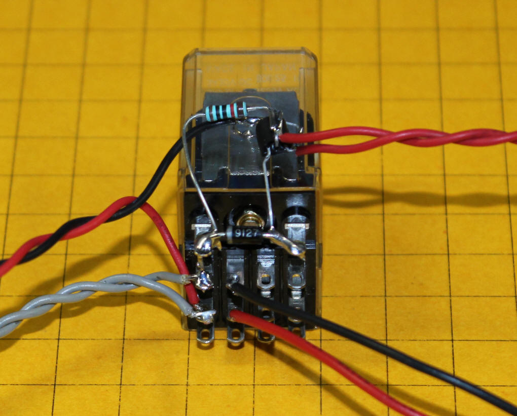
This more refined circuit shows a larger 12 volt relay, the transistor and other components as well as the connections that go to switches and the track.
Here is the back of the board. Note that the relay shown here is a 4PDT (Four Pole Double Throw) relay. That means that it has four sets of contacts. We are only using two of the sets so the remaining ones can be used for other purposes.

Video of the Train
The video below shows a small HO layout that demonstrates how the Once
Around works.
(right click the box below and select "play")
The last part of the video shows the addition of a capacitor that makes for a much smoother and more realistic stop. There is a detailed discussion of adding capacitors for this puropose here:
http://www.trainelectronics.com/artcles/capacitor/index.htm
Note that I am showing a single capacitor in the video. This is OK so long as you take care to keep the polarity consistent. Electrolytic capacitors have a bad habit of exploding if you connect them backwards!
Keeping the Train Running for More than One Lap
The circuits shown up to now all have the train completing only one lap
before stopping in the stop block. In order to have the train complete
more than one lap you need to add a timer to the circuit so that the start
button is activated for whatever time you want the trains to operate. Any
type of timer that has a relay with a set of normally open contacts can be used. Just
wire these contacts to the start switch. So long as the timer has those
contacts closed the train will run. When the contacts open the train will
complete its lap around the layout and stop at the stop block. Timers that
can be used are discussed in
Timers for Model Railroad Applications Part I and
Timers for Model Railroad Applications Part II.
Part II also has a related circuit that has a train run around the layout continuously. It only stops at a station for a time that is determined by a timer. The section that describes this is titled "Station Stop Timer".
Give it a Try!
I hope that this information has sparked some of your own ideas and may help
you to make your layout more interesting. Please let me know if you have
any questions.
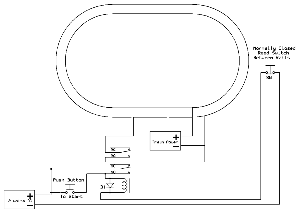
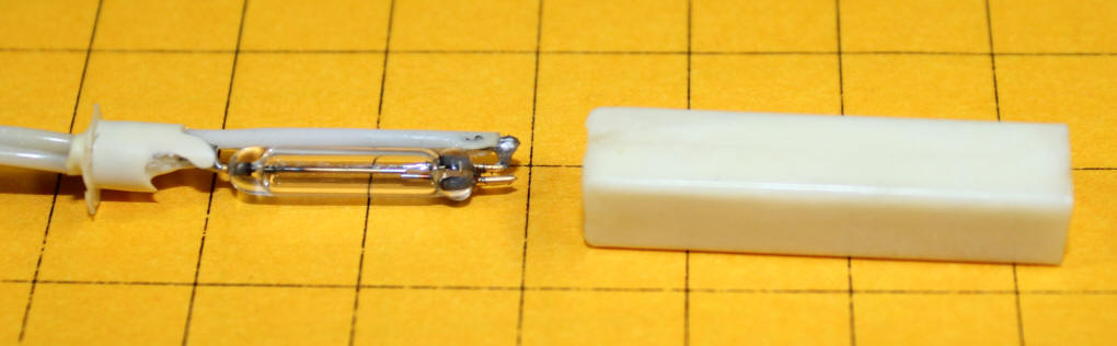
After completing this article I came across a source for inexpensive NC (Normally Closed) reed switches. As I mentioned in the article they could be used to simplify the circuit above. They were not used because they are frequently expensive and large in size.
Electronic Goldmine recently sent out an email of new products that included a Normally Closed reed switch for only $1.00. I ordered a few and disassembled one to make sure that it would work with this project. The good news is that the reed switch is small and should work very well! The bad news is that I have no idea of how many of these that they may have in stock - the could be gone already!
The switch is in a plastic enclosure that is at the end of a 3 foot long cable. It was easy to pick at the glue that sealed the end of the tube to free the switch. The reed switch itself is less than 2 cm in length (the squares below are 1 cm on a side).
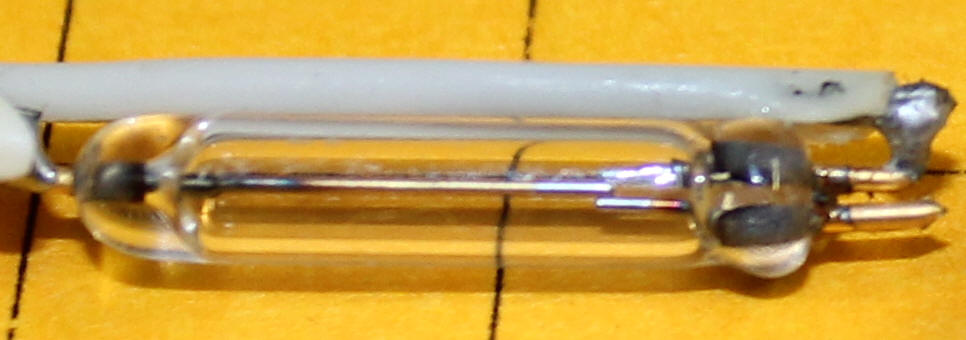
In this close-up you can see that the switch is actually a SPDT (single throw double throw) unit. The connection on the far left is the common terminal. There are two wires that exit to the right. The one that is used is the NC terminal while the NO terminal is not connected.
The revised schematic is shown here. It is much simpler with the NC reed switch taking the place of several components.