Garden Railway Sensors – Part II
Revised 3/17/2005 5:19 am
In part I of this article on sensors we dealt with mechanical and reed switches. In part II we will take a look at another device that can be used as a sensor in garden railway applications. I think that you will find its capabilities and use very interesting and appropriate with some of your projects.
Hall Effect Sensors
Hall Effect sensors are the electronic equivalent of a reed switch. You can think of them as a cross between a reed switch and a transistor. They are frequently used to determine the rotational speed of a spinning device, such as the platter of a hard drive or the drive shaft of an automobile. A small magnet is attached to the spinning object so that it goes past the Hall sensor as it rotates. The sensor sends one pulse to a counting circuit each time the magnet passes. I have also seen computer keyboards that have a magnet under each key that comes close to a Hall sensor on each key press. A nice system as there are no mechanical switches to wear out!
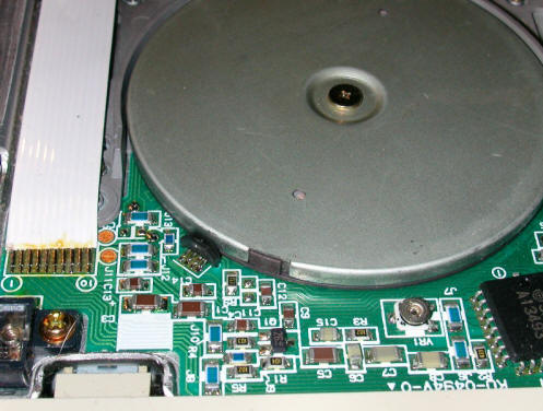
This photo shows the bottom side of a computer's floppy disk drive. The rotational speed of the platter is measured by the small Hall Effect sensor that you can see at the 7:00 position. Just to its right you can see the small magnet that is attached to the platter. By measuring the time needed for each rotation the speed can be measured and adjusted by the electronics on the drive.
In garden railway applications Hall Effect sensors can be used in most places where a reed switch would be employed. Their main advantage is their small size and lack of mechanical parts that are prone to failure. On the down side you must run three wire cable to them and it can take a bit more circuitry to connect them to another device. In addition most Hall Effect sensors, such as the one used in this article, respond to only one of a magnet’s poles. This forces us to be a bit more careful when mounting magnets that will stimulate a Hall Effect sensor.
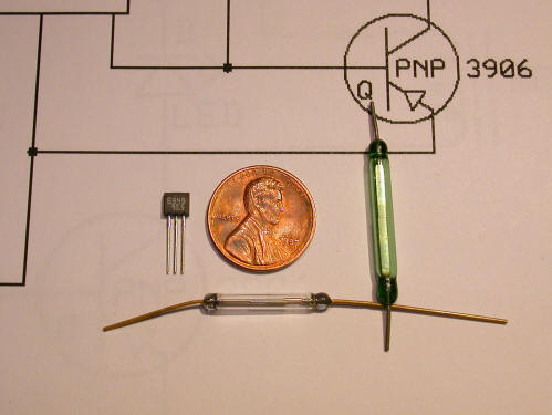
The device I am working with here is Panasonic part number DN6848-ND. It is available from Digi-Key (http://www.digikey.com ) for a little more than $1.00 each in small quantities.
The DN6848 Hall Effect switch is to the left of the penny in the photo below.
The open collector output of this sensor provides for a fairly straightforward connection to other devices. The schematic below will allow you to test the operation of the sensor. Even though the DN6848 will operate from voltages from 5 to 16 volts try to stick with the lowest operating voltage when testing and experimenting.
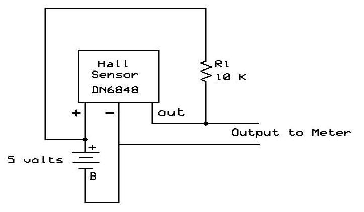
When the south pole of a magnet is brought near the front (label) side of the sensor the voltage displayed on the meter should drop from 5 volts to 0 volts. When the magnet is removed the voltage should return to 5 volts.
Interfacing with Sound Boards
Hall Effect sensors can be used to directly trigger some of the sound boards that were described in the two parts of Give Your Railway a Voice. All you need to do is to provide a common ground and connect the output from the Hall sensor to the activation switch. A bit of experimentation may be needed but I got several of them to work using this method. If you do give this a try I would suggest using a current limiting resistor, 1000 ohms or so, in series with the Hall output when connecting to the activation switch. Might prevent some unfortunate results!
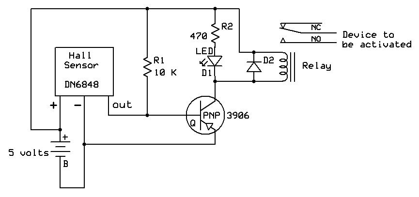
The safest way to connect a device, however, is with a relay. Examine the schematic below to see what is involved. The relay can be any 5 volt unit such as the reed relays that are sold by Radio Shack (# 275-232). The PNP transistor (2N3906, 2N2222 or equivalent) turns the relay on when the output from the DN6848 drops to 0 volts. The LED, D1, is just an indicator to show that the relay has been activated. The diode, D2, (1N40001 or equivalent) across the relay's coil protects the circuit from a spike that is generated when the relay is turned off. To activate the sound board just connect the wires from the terminals that start the sound to the NO and common terminals of the relay.
Latching a Relay
You will note that this circuit will only activate the relay for a moment as the train carrying the magnet passes or as a train passes over a magnet. This is sufficient if the device you are activating with it, such as a sound board, completes its event after being given a pulse. If you are activating a track side event, such as turning on crossing gate lights, you would be better off with a circuit similar to the one described in the first sensor article where one reed switch turns the relay on and a second reed switch, somewhere farther on down the track, turns it off.
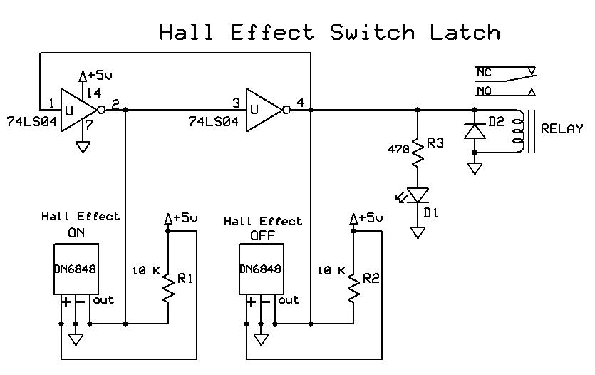
The easiest way I have found to create such a latching relay with the Hall sensors is to employ a single integrated circuit, a 7404 hex inverter. This is an old standard TTL chip that has been around for decades. It is a 14 pin device that contains 6 individual inverters. An inverter takes a logic level, such as +5 volts or ground, and inverts it. If the input pin has 5 volts applied to it the output will show 0 volts. If the input pin is at 0 volts the output will show 5. This device is one of the primary building blocks used in digital devices and can be configured to do many things. The circuit below shows how to connect a 7404 to two Hall Effect sensors and a relay. When the Hall sensor on the left comes near a magnet the relay is latched until a magnet comes near the second Hall sensor when the relay is turned off.
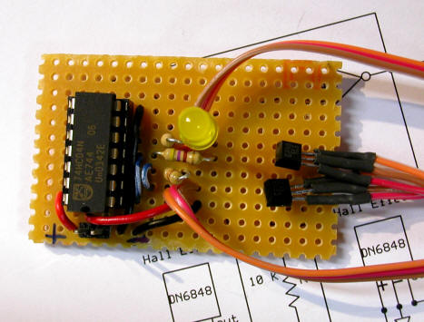
Here is a photo of a working version of the above schematic. The 7404 is on the left, the power connection for +5 volts is just below it, the LED indicates when it is on or off (the relay has not yet been installed) and the two Hall Effect sensors are shown on the right. Note that they are soldered to long lengths of 3 conductor wire.
If you use this circuit I would suggest placing the two sensors on opposite sides of the track, with the "on" sensor 1/2" left of center and the "off" sensor 1/2" right of center. Place a magnet on the engine so that it will go over the "on" Hall Effect sensor and place a magnet on the last car so that it goes over the "off" sensor. This way your event starts when the engine passes the first sensor and ends when the caboose passes the other. If you just depend on one magnet on the engine to go over both sensors the event may end long before the train passes - not a good thing if it is a crossing signal!
Going Farther with the 7404
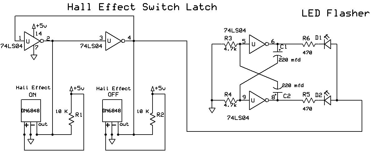
You may have noticed that the 7404 chip that was used in this application is made up of 6 discrete inverters and that we are only using 2 of them. This seemed like something of a waste to me so I spent a bit more time on the circuit and turned two of the other inverters into an oscillator circuit that is attached to two red LEDs. The LEDs flash on and off alternately something like a pair of lights on a railroad crossing. The schematic is below. You will notice that it takes the output from the first circuit and uses it to activate the LEDs in the oscillator section.
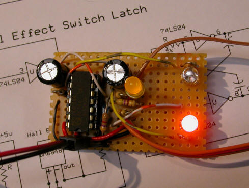
Although this looks like an efficient way to add two flashing lights the picture below shows why it may not be the best way to accomplish this. As you can see the board has become very crowded with the addition of four resistors, two LEDs, two capacitors and many wire jumpers.
Duplicating this circuit with an inexpensive microprocessor, as you will see in a future article, results in a much smaller device with a dramatically reduced part count.
I hope that this description of the Hall Effect sensor and some of the things it can be used for in a Garden Railway system has been of interest and value to you. Please let me know if you give it a try!