Ditch Lights and Pulse Width Modulation
revised 5-10-06 / 12-13-07 / 3-16-10 / 12-29-10
Click here for additional notes on the Ditch Light project
While attending the East Coast Large Scale Train Show a friend and I noticed the distinctive flashing ditch lights on several engines. After the show he asked if I could come up with a circuit that would duplicate the effect. Not being one to shy away from a challenge I spent a few days thinking this over and eventually stumbled upon a somewhat elegant solution to the problem that might be of interest to others.
The ditch light behavior that I wanted to duplicate was not simply a matter of alternately turning one light on as the other is turned off. The action is much more like the lighthouse beacon project that I wrote about last year. In a lighthouse the lamp appears to slowly brighten to maximum brightness then slowly dim to nothing. See Upgrading your Wal-Mart Lighthouse for more background on how a simple microprocessor can be used to gradually turn a bulb or LED on and off.
I wanted to use the same Picaxe microprocessor for this project but in this case there was an added complication. When working with the lighthouse there is only one bulb. That works out well as the Picaxe only has one Pulse Width Modulation (PWM) output channel to control the bulb's brightness. (You may recall from other articles that I have written that PWM is a technique used with microprocessors to simulate generating a variable output voltage from a pin that is normally either full on or full off.) I spent a good bit of time perusing specification sheets and experimenting with more advanced PIC microprocessors that are able to have multiple channels of PWM. I had some success but I was never 100% happy with the results of those experiments. I eventually discovered that I could use a single PWM channel to control the two ditch light LEDs if I wired them correctly.
Back-to-Back LEDs
This would be a good time to review how LEDs work. You will recall that LEDs are diodes and that they only produce light when connected with the proper polarity. They must also be wired with a current limiting resistor in series with one of the leads to make sure that they don't burn themselves out by consuming a diet too rich in electrons! (For more information on LEDs see my article: A Simple Constant Brightness LED Light )
The circuit below shows a single LED, its current limiting resistor and a 9 volt power source, a transistor radio battery. For those of you who may not be familiar with schematic symbols the triangular symbols pointing down indicate that those two leads both go to a common ground connection. I could have just shown them connected together but thought I would start using the ground symbol here as it appears a good bit later on in other diagrams.
If the circuit is wired as it is here the LED will light when the power is connected since the LED's anode is connected to the positive terminal of the battery, through resistor R1, and its cathode is connected to the negative terminal. If you reverse the connections to the battery the LED will not light, but, more importantly, it will not be damaged as the current limiting resistor prevents excessive current from passing through it and burning it out.
Here is a diagram that will help you to identify the anode and cathode of LEDs.
What I decided to do for the ditch lights was to wire two LEDs in parallel, one in the orientation pictured above and one backwards. With this setup if the battery is connected with its positive terminal to the left LED1 lights. When the battery is connected the other way LED2 lights.
The following schematic should give you a good idea of what comes next when the circuit is connected to a microprocessor. The two LEDs are still wired back to back but the anode of LED2 is connected to + 5 volts and the cathode of LED1 is connected to ground. The connections on the left are joined together and are run to a potentiometer (variable resistor) that can be turned to vary the voltage from zero volts to 5 volts.
If the potentiometer's knob is rotated full left one LED lights fully and the other is out. If it is rotated to the right the opposite happens. Any position in between has one brighten as the other dims. I am sure you know what happens if it is the center position!
In order to use this with PWM all you need to do is to substitute the PWM output pin on the Picaxe for the variable resistor. Now when the Picaxe sends out PWM pulses the LEDs will see a signal that is negative for some of the time and positive for the other. The higher the PWMOUT value, that is the closer it is to 5 volts, the brighter the first LED will become and the dimmer the second will be. As PWMOUT goes closer to zero volts the second LED will brighten as the first dims. By varying the PWM output we can have the pair of LEDs see a continuously changing voltage that goes from zero to 5 volts and back to zero again, giving continuously changing brightness. As with the variable resistor, when the PWM duty cycle is 1/2 on and 1/2 off the LEDs' brightness is equal.
This is exactly what the ditch lights need to do. By controlling the PWM output the Picaxe can easily control the brightness in the two LEDs. If the LEDs are well matched with the same value current limiting resistors they will be balanced and change in intensity as one goes up and the other down in brightness.
PICAXE
Connecting the LEDs to the Picaxe is very simple. It is just a matter of connecting the Picaxe pin that is putting out PWM to the LEDs. In the schematic below all of the items to the left of the Picaxe (the DB9 and two resistors) are only needed to program the Picaxe. If you are using a pre-programmed Picaxe or are programming it on another board all you need is the LEDs, a 0.1uf filtering capacitor and the Picaxe. Connect them up to a source of 5 volts and away you go. There is a very detailed article on supplying 5 volts to model train projects here)
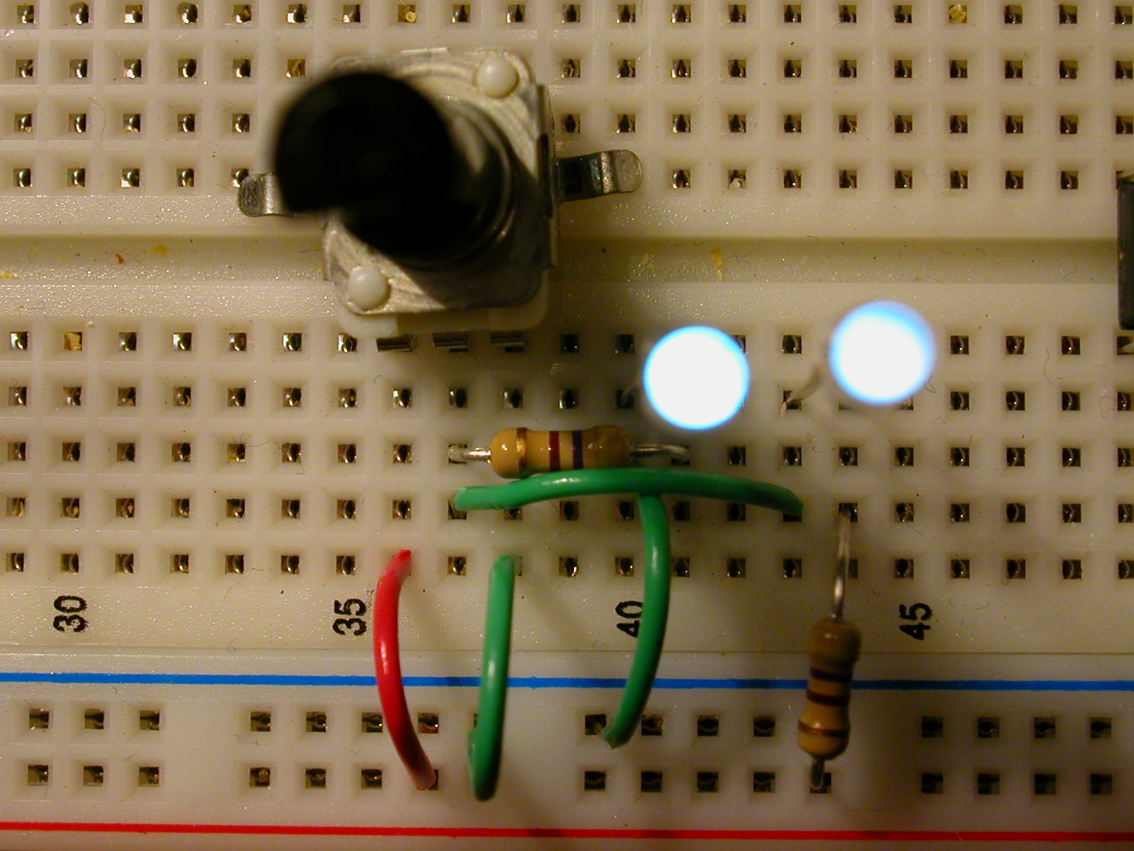
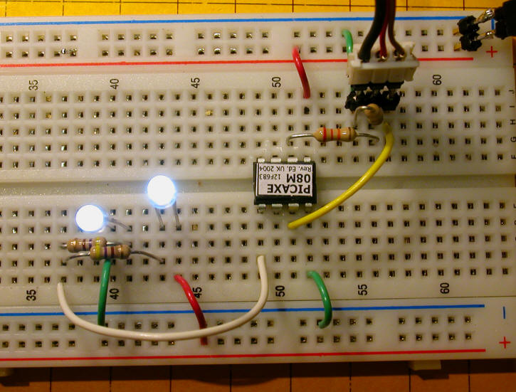
The photo below shows the small number of parts required to make this all work! Keep in mind that the plug, resistors and yellow wire in the upper right are only needed for programming. (Note: If you are not using the programming resistors in your circuit make sure you connect pin 2 to ground. The Picaxe will NOT work if pin 2 is not connected to either ground or the programming resistors.)
SOFTWARE
Although I will be glad to supply pre-programmed Picaxe chips (see notes at the end of the article) this might be an opportunity to try programming them yourself as the software to make this happen is both simple and easy to follow. There is a detailed description of how to make up a programming cable, download the free software and program a Picaxe in the library under: Robot Trains in the Garden - the entire article (3 parts) is available as a series of PDF files at the end of each section. There is also a wealth of information on the web at http://www.picaxe.com .
A few comments on the program below may help:
| REM
d.bodnar 4-25-06 rev1 REM ditch light experiment SYMBOL led = 2 SYMBOL temp = w0 'for/next variable SYMBOL Rate = b8 SYMBOL skip = b9 rate = 10 'adjust these two variables to skip = 30 ' change the speed of flashing REM higher rate = slower flash REM higher skip = faster rise/fall of flash again: FOR temp=0 TO 1023 STEP skip PWMOUT led, 255, temp PAUSE rate NEXT temp FOR temp=1023 TO 0 STEP -skip PWMOUT led, 255, temp PAUSE rate NEXT temp GOTO again: |
GOING FARTHER
The program and circuit do exactly what was planned but, as usual, I can't leave well enough alone! We are, after all, only using one of the Picaxe's five input/output pins. It didn't take long to add circuitry and software that allows you to use a potentiometer to adjust the rate at which the lights change. That way you don't have to reprogram the Picaxe to make simple adjustments. The circuit modification is trivial. Adding a 10,000 ohm potentiometer that has one of its outer terminals connected to +5 volts and the other outer terminal to ground allows us to deliver a variable voltage from 0 to 5 volts from the pot's center pin to a Picaxe pin. The Picaxe's READADC (READ Analog to Digital Converter) command can convert this varying voltage to a number and that number can be used in the program to control the speed.
Here is the hardware modification. The only change is the addition of R7, a potentiometer. Its outer pins go to +5 and ground while its center pin goes to the Picaxe's pin 6 which is "in1". Note that any value potentiometer from 1000 ohms up will work, just make sure it is a linear taper, not an audio taper potentiometer. Note that using a potentiometer with a resistance less than 1000 ohms will draw more current than necessary as the positive and negative terminals of the power supply run through it. Also note the .1uf capacitor, C1, in the circuit. This is a small decoupling capacitor that should be soldered to the Picaxe as close to pins 1 and 8 as possible. Your circuit may work without it but if you experience intermittent or "strange" behavior during operation this is the first fix to try. I have found that they work like magic to cure a host of ills!
The changes are in italic type in the program below. The number returned by the potentiometer through READADC is used to adjust the rate of the flashing of the LEDs.
| REM
d.bodnar 4-25-06 rev1 REM ditch light experiment SYMBOL led = 2 SYMBOL temp = w0 'for/next variable SYMBOL RatePin = 1 SYMBOL Rate = b8 SYMBOL skip = b9 skip = 30 REM higher rate = slower flash REM higher skip = faster rise/fall of flash again: FOR temp=0 TO 1023 STEP skip PWMOUT led, 255, temp READADC ratepin, rate PAUSE rate NEXT temp FOR temp=1023 TO 0 STEP -skip PWMOUT led, 255, temp READADC ratepin, rate PAUSE rate NEXT temp GOTO again: |
ONE LAST MODIFICATION
The last modification does two things. Rather than using a potentiometer to change the rate of the flashing we will tie that pin to the track voltage so that the rate changes with speed. We will also set a point at which the lights will not flash but will both stay on at equal brightness.
This requires a few more circuit changes. Since the Picaxe can only deal with voltages in the range of 0 to 5 volts applying track voltage, which can easily exceed 20 volts, would quickly fry the chip. The best way to deal with this is to use a pair of resistors as a "voltage divider". If we want to deliver a portion of the track voltage we just use a 10K resistor and a 50K resistor wired as in the schematic below. The resistors effectively divide the input voltage, by roughly 5, so that the Picaxe pin never sees anything even close to 5 volts.
The bridge rectifier in the schematic is necessary because your track or battery provided power can be reversed to change the engine's direction. Bridge rectifiers provide consistent positive and negative terminals. If you are using an on-board power supply circuit that has a bridge rectifier you can use that connection to feed the voltage divider and "in1" on the Picaxe.
The modified code is below. It still uses the READADC command to get the voltage. In addition a line was added to test for the track voltage being above a reading of 120. If it is the program jumps to the end where the LEDs are set to the same brightness. Adjust this value to change the point where the flashing will stop.
| REM
d.bodnar 4-25-06 rev1 REM ditch light experiment SYMBOL led = 2 SYMBOL temp = w0 'for/next variable SYMBOL RatePin = 1 SYMBOL Rate = b8 SYMBOL skip = b9 skip = 30 REM higher rate = slower flash REM higher skip = faster rise/fall of flash again: FOR temp=0 TO 1023 STEP skip PWMOUT led, 255, temp READADC ratepin, rate IF rate > 120 THEN AllOn: rate=rate/20 PAUSE rate NEXT temp FOR temp=1023 TO 0 STEP -skip PWMOUT led, 255, temp READADC ratepin, rate IF rate > 120 THEN AllOn: rate=rate/20 PAUSE rate NEXT temp GOTO again: AllOn: |
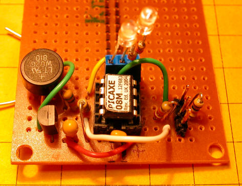
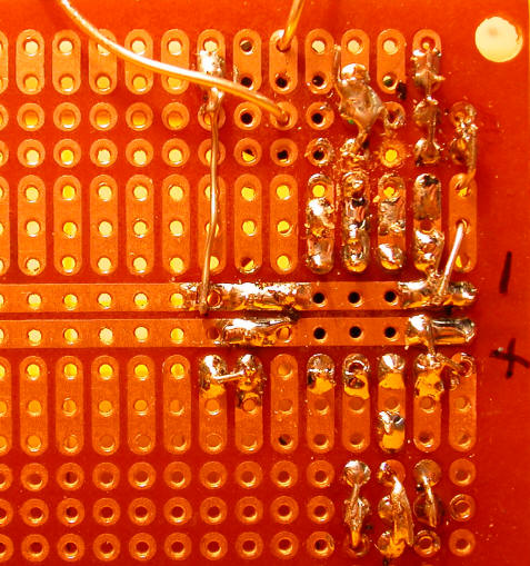
The circuit can easily be constructed on a simple circuit board such as Radio Shack's 276-148. The prototype that I wired is shown below, both front and back. The bridge rectifier is in the upper left, the programming circuit in the lower right and the voltage regulator in the lower left. The two bare wires visible in the two photos are the inputs to the bridge rectifier.
ANOTHER THOUGHT
There was some discussion about ditch lights on a large scale forum as I was preparing this article and I would like to add one more modification that speaks to these comments. Many observers reported that they had seen trains flashing their ditch lights when they blew their horns. At other times the lights were on but did not flash. To duplicate this behavior all we have to do it use one of the remaining Picaxe pins to trigger the ditch lights so that they stay on for a set number of seconds or repetitions.
To activate the ditch lights this pin can be connected to the horn activation contact on the sound board. This is best done through an optoisolator. An optoisolator is a 6 pin integrated circuit that contains an encapsulated LED and light detector.
The LED section of the device (pins 1 and 2) is connected to the output of the sound board and the detector section (pins 5 and 4) goes to the Picaxe. Although using an optoisolator is not required in all cases using this device effectively isolates the sound board from the Picaxe so that there is little chance of one damaging the other. It is cheap insurance!
The program change below is based on the first program but the modification could easily be made to any of the versions of the software. Additional comments should help you to follow the program flow. At the label "top" the PWMOUT command sets both lights to the same brightness. The next line waits for the trigger change at pin 3. If it is not seen the program goes to back to the "top" and the lights remain steady. If it is seen the program branches to "flash". The main FOR/NEXT loop has the lights brighten and dim 50 times. After that completes the program goes back to "top".
| REM
d.bodnar 4-25-06 rev1 REM ditch light experiment SYMBOL led = 2 SYMBOL temp = w0 'for/next variable SYMBOL Rate = b8 SYMBOL skip = b9 SYMBOL loop1 = b10 SYMBOL trigger = pin3 rate = 10 'adjust these two variables to skip = 30 'change the speed of flashing REM higher rate = slower flash REM higher skip = faster rise/fall of flash top:
|
If you don't have a sound board on your engine you can connect the Picaxe's pin 4 (in3) to a reed switch that is mounted on the bottom of the engine. A magnet on the track can be used to trigger the flashing lights as the train approaches a crossing or station. Simply connect one side of the reed switch to +5 volts and the other to pin 4. In addition connect pin 4 to ground through a 10 K resistor. This will keep the pin low until the reed switch is activated. This option is shown to the right of the optoisolator in the schematic above.
I think that these flashing lights can add a bit of interest and realism to a model railroad engine. They could also be used in crossing signals or other applications where you want to get someone's attention. I encourage you to give this project a try!
| Parts list:
Flashing Ditch Lights
Miscellaneous
The following items are available from the author: Custom circuit board - I have not designed and created a custom circuit board for this project due to the expense of ordering a small number of boards. In quantities of 12 my cost would be about $7.00 each. If enough interest is shown in custom boards (drop me a note at dave@davebodnar.com ) Bright white 3mm LEDs. I have a number of VERY bright 3mm (smaller than the standard 5mm units) white and green LEDs. The fit nicely into the front of engines and into other tight places. The cost is $0.50 each + shipping Programmed Picaxe only. $6.00 + shipping (specify which of the program from the article you want on the Picaxe) I have given Radio Shack part numbers for most of the parts used in this article but you are likely to find much better prices from other vendors, including Hosfelt ( www.hosfelt.com ), Digikey ( www.digikey.com ), Electronics Goldmine ( www.electronicsgoldmine.com ), Jameco ( www.jameco.com ) and Glitchbusters ( www.glitchbusters.com ) - I have links to these and other vendors on my web page at www.davebodnar.com, Email: dave@davebodnar.com |
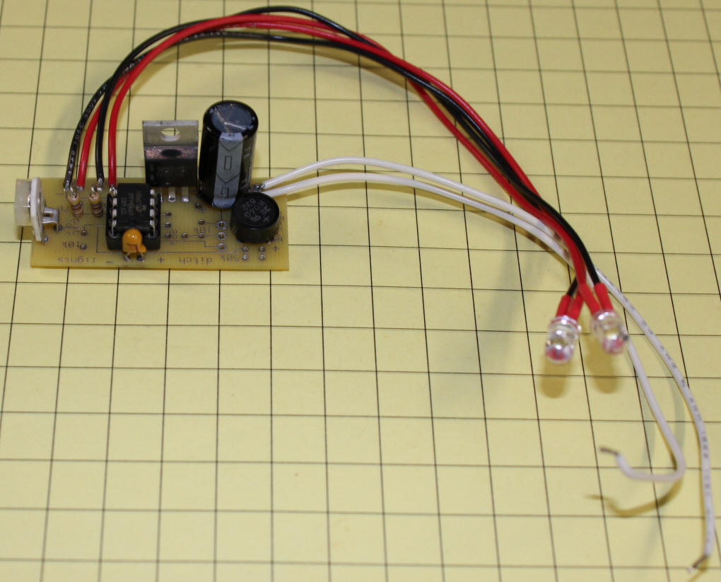
The photo below shows the latest revision of the circuit board. The white wires on the right go to track power of any polarity. The two LEDs are at the ends of the pairs of red/black wires. The device at the far left is a potentiometer that is used for speed control.