Pulsed Infrared Sensors
d. bodnar 4-09-05 3:59 pm (2-10-2012)
Over the last two articles on garden railway sensors we dealt with devices that can give good service when properly installed and utilized. There are many other options including audible & ultrasonic sound sensors and devices that sense visible light such as photo transistors and CdS cells. All of these are appropriate for use in some situations but not necessarily in an outdoor environment where weather and mother nature play havoc with electronic devices.
The Best Sensor Yet?
In this article I would like to concentrate on the one sensor that I have found to be the most reliable non-contact sensor for outdoor garden railway use, the pulsed infrared sensor. Although this device is similar to other units that use an infrared emitter and detector or visible light sensors it differs in that its two main components are designed to produce and react to pulses at a set frequency. Pulsing the IR emissions, usually at 38,000 cycles per second or 38 kHz, makes this setup much less prone to interference from sunlight and other sources of infrared radiation.
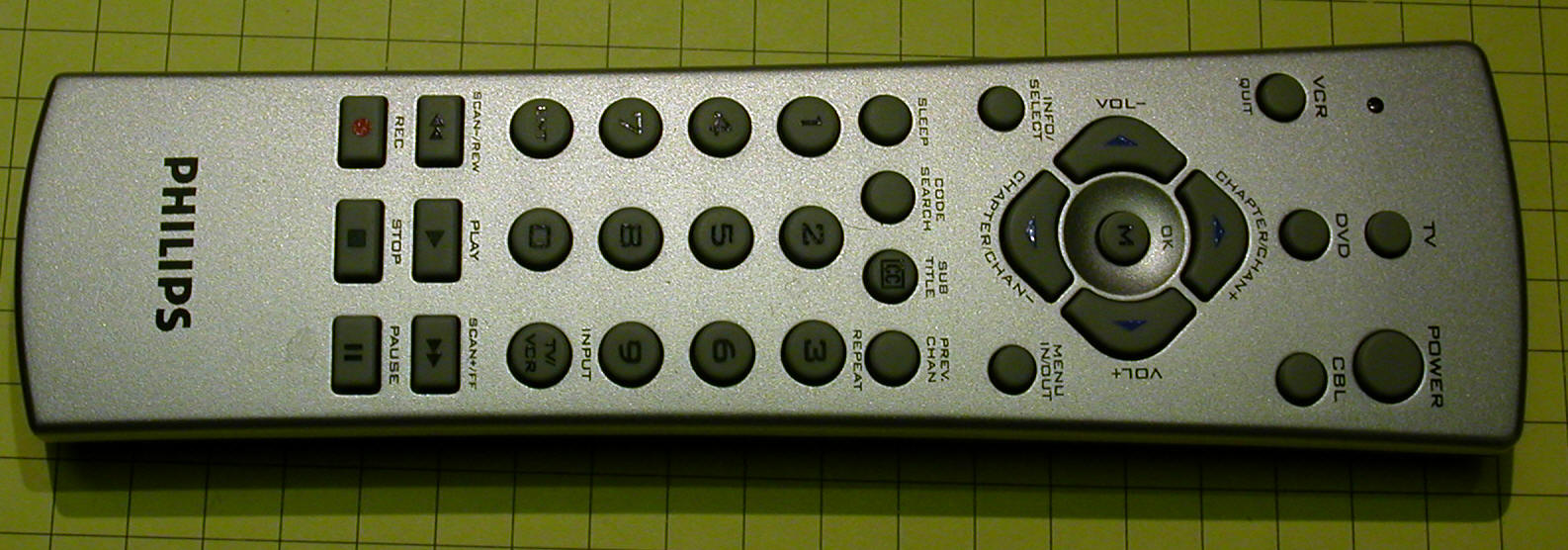
To give you an idea of how common and reliable this technology is, virtually every TV remote control made for the last 20+ years has used pulsed IR to help you select channels and adjust your volume!
Sensor Placement
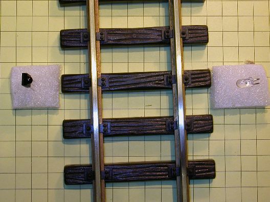
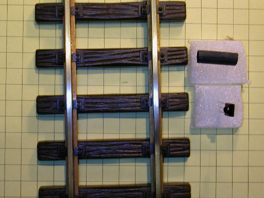
The emitter and receiver module can be placed on either side of a piece of track and connected to a device that you want to start when the beam of pulsed IR is interrupted. This is a great way to trigger trackside events whenever a train goes by. Note that the photo shows only the emitter (clear object on the right) and the receiver module (black object on the left) without any wiring or supporting circuitry. Also, for simplicity's sake, the emitter and detector are placed directly across from one another. A better placement may be to put them at a diagonal to the track so that the beam remains broken even when gaps between cars go by.
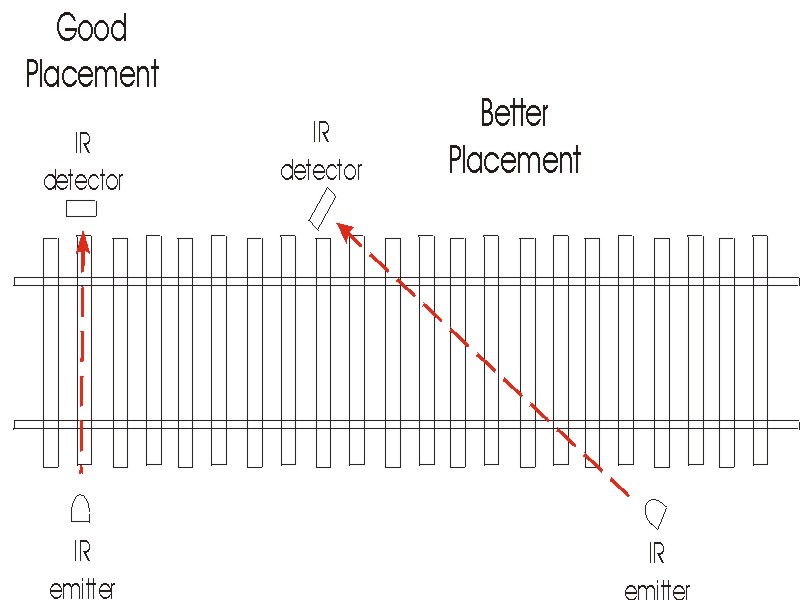
A second method of placing these devices has more interesting possibilities. You may have noted that your TV remote doesn't work very well when your dog or some other object blocks a line-of-site path for the IR beam. That is a good illustration of what happens in our first example. You may have also noticed that you can face a remote control away from your TV and bounce the IR beam off of a wall behind you or to the side and still control the TV. Depending on the reflectivity of the surface you are utilizing you can get almost as good a result as with a direct path. This is the key to the second method of use for our sensor. Mount the IR emitter next to the IR detector, shielding the detector so that there is no direct path from the emitter to the detector. The easiest way to do this is to put the emitter inside of a piece of tubing so that the beam can only go out the front.
Both devices, the emitter and receiver are placed as show here. This setup, as noted above, will not work because enough IR is emitted from the sides of the IR LED to keep the receiver on at all times.
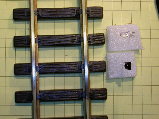
The addition of a shield, in this case a piece of opaque black tubing, removes the direct path between the IR LED and the sensor. Infrared must be reflected from a passing train to reach the receiver.
38 kHz Pulse Generator with a 555 Timer
Now that we have an idea of how this sensor works let's get about the business of putting it all together. First we need to build an oscillator to generate the 38 kHz pulses that will drive the IR LED. There are a number of ways to do this. The traditional method is to use an integrated circuit called a 555 timer. This device can generate pulses over a wide range of frequencies by adjusting the values of a resistor and a capacitor. If a variable resistor, or potentiometer, is used you can easily adjust the frequency to a precise value. The schematic below shows a 555 timer set up to generate pulses in the 38 kHz range. D1 is the infrared LED, C1, R2 and R3 determine the frequency of the pulses. R3 is a variable resistor or potentiometer that can be adjusted to get an exact frequency.
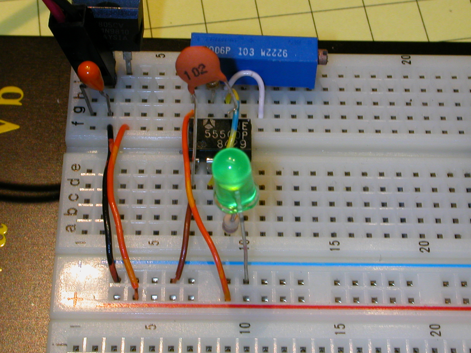
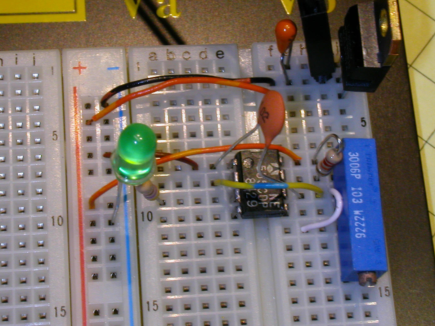
| Sidetrack #1: The photos below show two views of the circuit constructed on a prototyping board, sometimes called a "solderless bread board." These boards are available from many sources, see the parts list at the end of the article for details The holes on the board accept standard components such as ICs, resistors, capacitors and transistors. You simply plug the component into the board and connect things together with short wire jumpers. The pins in each 5 pin row are electrically connected together so that you have 5 positions where a wire or component can be inserted. In the photo the 555 timer's 8 pins are inserted in holes in rows 7 through 10 and in columns "e" and "f." Pin 1 is in hole E7, pin 2 in e8 and so on. If you compare the schematic and the photo you will find that the wiring is identical. You can see in the schematic that pin 1 of the 555 goes to ground and that there is a brown wire going from that pin to the horizontal bus marked with a "-" and a blue colored line. You will also see that pins 4 and 8 of the 555 go to +5 volts and that an orange wires connect those two pins with the horizontal bus marked "+" and accompanied by a red colored line The tan device that is marked 102 is the capacitor and blue rectangular device is the variable resistor. For testing a visible green LED was used rather than in infrared LED. The variable resistor is called a multi-turn 10K ohm potentiometer as it varies from 0 ohms to 10,000 ohms by turning the screw head that is visible at the right. It takes several turns of the screw go to from 0 to 10,000 ohms giving you great control over an exact frequency setting. (Note: The only device in the photo that is not in the schematic is the voltage regulator (7805) that is in the upper left hand corner of the first photo. It is there to supply 5 volts to the breadboard. - see my earlier article on voltage regulators for details on this device.) |
 a
a
There are two disadvantages to this method of frequency generation. First, the frequency can change with temperature variations and as the components age. Secondly, one needs to have a frequency counter to do the initial setup. That is, you must connect the output of the 555 timer to an external frequency counter and adjust the variable resistor until the frequency reaches exactly 38 kHz.
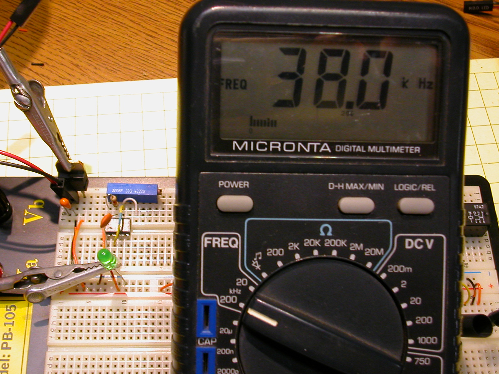
| Sidetrack #2: Although I list having to use a frequency counter as a disadvantage of the 555 circuit it is not really big a problem as they are readily available. Radio Shack and a number of other suppliers offer digital multimeters, such as the one in the photo above, that include frequency counters. All that you have to do to check the frequency is to connect the black lead from the meter to ground and the red lead to the pin where the output pulses appear. This might be an opportunity to upgrade your meter or to purchase your first one! |
38 kHz Pulse Generator with a Microprocessor
Although a bit more expensive to implement, around $5.00 for the microprocessor circuit vs. a few dollars for the 555 timer circuit, a microprocessor can be used to generate our series of pulses. The cost is more but the device is very stable, is not prone to drifting, the parts count is reduced and you don't need to calibrate it with a frequency counter.
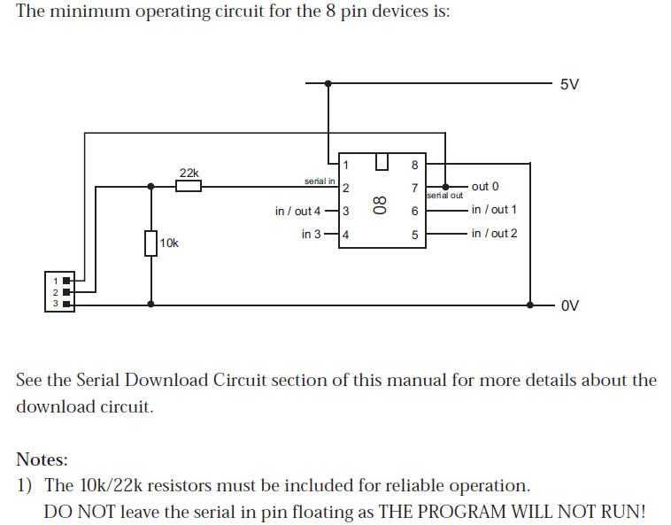
In the schematic below a Picaxe 08M microprocessor has been programmed to create a stream of 38 kHz pulses at pin 5. The only parts that are necessary to make this work are the 08M, a current limiting resistor and the IR LED. The 2nd LED and resistor, connected to pin 6, are just there to visually show that the system is working by flashing on and off. Even the filter capacitor is not necessary if you are running off of a clean battery power supply. Note that the resistor connected to the IR LED is considerably smaller (180 ohms vs. 470 ohms) than the one on the visible red LED. Even though the 180 ohm resistor allows quite a bit more current to flow to the IR LED it should not be a problem as the LED is on for a very short time as it pulses.
![]()
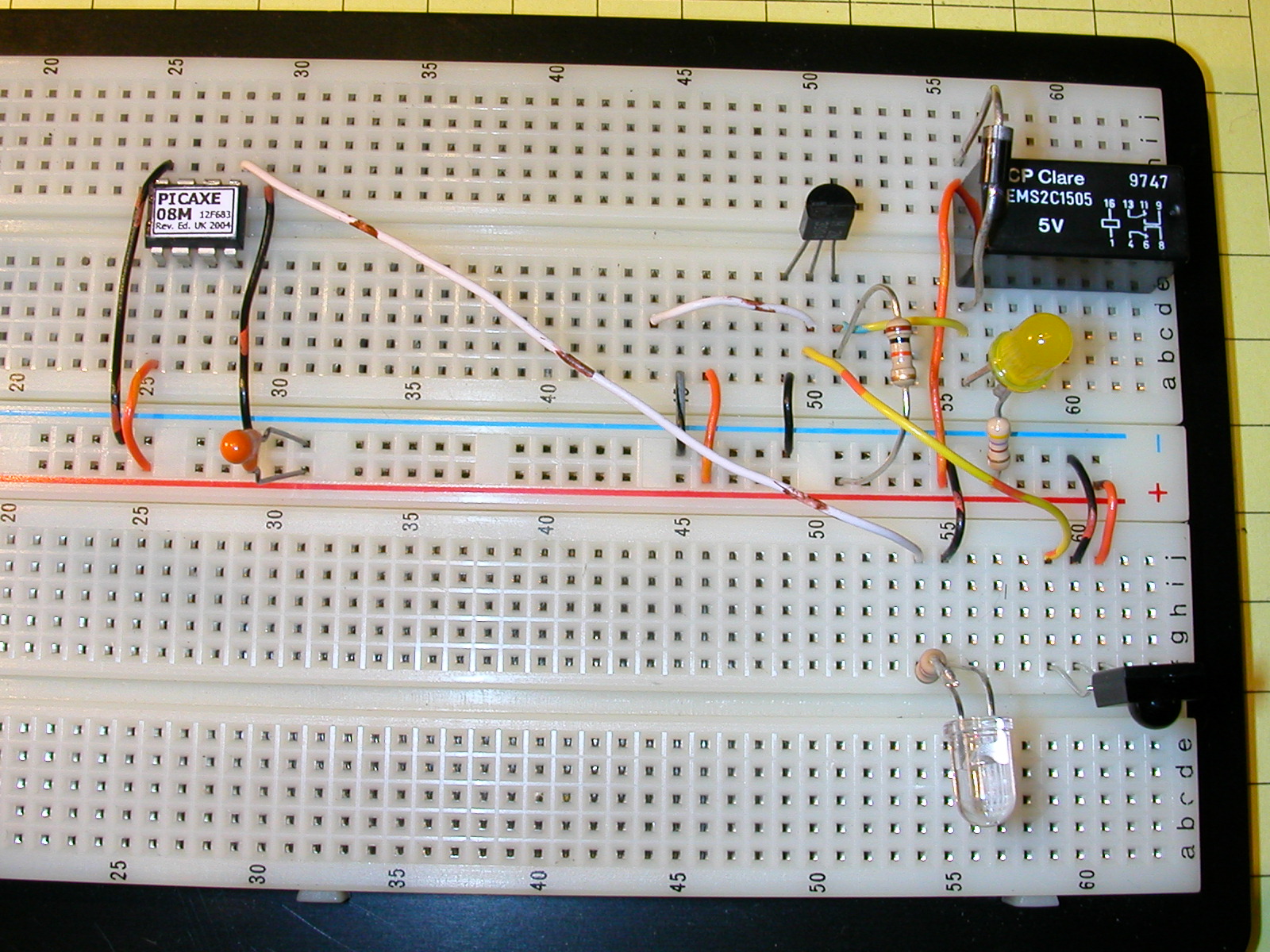
In the photos below the black jumper connects pin 8 of the Picaxe to ground, the orange wire connects pin 1 to + 5 volts. The red LED has the resistor soldered to one of its pins and goes between pin 6 on the Picaxe and the black jumper that goes to ground. The infrared LED also has its resistor attached and goes between pin 5 on the Picaxe and ground.
![]()
![]()
Below are two programs for the Picaxe. I think that you will agree that they are simple as well. The first program turns on the two LEDs which flash on for 3/10 of a second then off for another 3/10ths. This program is great for testing as it will pulse your detector on then off then on then off so you can better see that it is working.
rem d.bodnar 4-9-05
rem sends 38 kHz pulse to IR LED - on/off/on/off
symbol irled = 2 'IR LED is connected to output pin out2 symbol LED = 1 'red LED is connected to output pin out1 main: high LED 'turn on red LED pwmout irled, 25, 52 'PWM on for 26 usec period 38.4kHz pause 300 'pause 3/10 seconds low LED 'red LED off pwmout irled, 0, 0 'turn the IR LED off for a moment pause 300 'pause another 3/10 seconds goto main 'go to start and do it again |
The second program turns the IR and the red LED on continuously. This is the program you are likely to use with a track side sensor setup.
rem d.bodnar 4-9-05
rem sends 38 kHz pulse to IR LED - constant on
symbol irled = 2 'IR LED is connected to output pin out2 symbol LED = 1 'red LED is connected to output pin out1 main: high LED 'turn on red LED pwmout irled, 25, 52 'PWM on for 26 usec period 38.4kHz goto main 'go to start and do it again |
Resistors may be needed
According to the PICAXE manual the two programming resistors may be needed
for reliable operation
38 kHz IR Detector
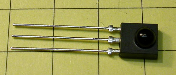
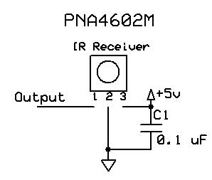
If you think that generating 38 kHz pulses is pretty easy you are going to be even happier with the hardware needed to detect them! Since so many home entertainment products use infrared remote control, detection devices have evolved over the years until they are just a single, 3 wire device, pictured below.
This device I am using is part # PNA4602M from Panasonic. It is designed to react to 38 kHz IR pulses. Note that there are different versions of this device that are tuned to different frequencies. The circuit needed to operate it is simplicity itself. The 0.1 uF bypass capacitor that is in the schematic is not necessary for testing but it is recommended if the leads between the sensor and the other parts of the circuit are very long, as they would be in a trackside installation.
Here is the test circuit on the breadboard. An LED with a current limiting resistor soldered to its positive lead is connected between the output pin and ground. Note that the bypass capacitor is not installed for testing.
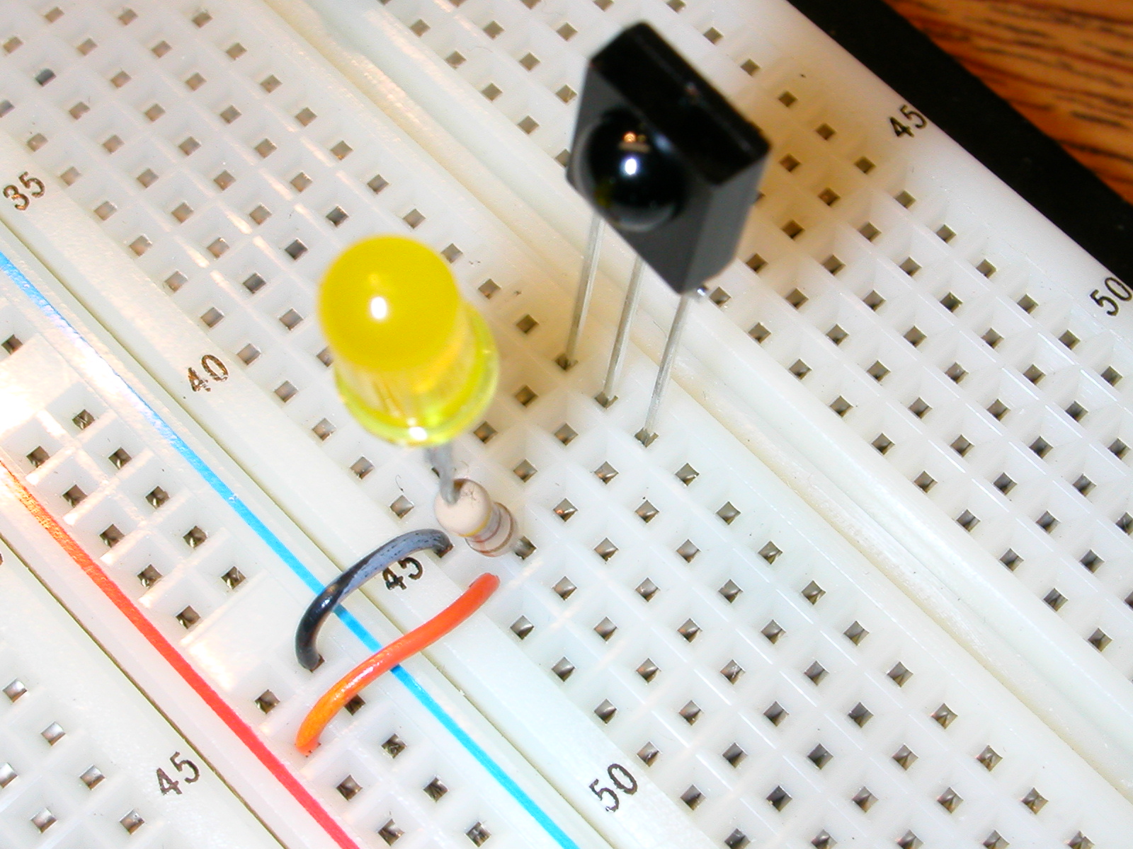
Test the device with the LED above or just attach a volt meter between pins 1 and 2 (output and ground). When it sees a 38 kHz IR signal the meter will show 5 volts. When it does not the meter will show 0 volts. You can easily test it by pressing buttons on a TV remote control and observing the volt meter or LED. Attaching the sensor to a relay only requires a single transistor switch and a few other components. The LED, D3, is there to show when the relay is activated. Diode, D1, protects the circuit from the surge that is produced by the relay's coil when it is turned off.
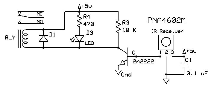
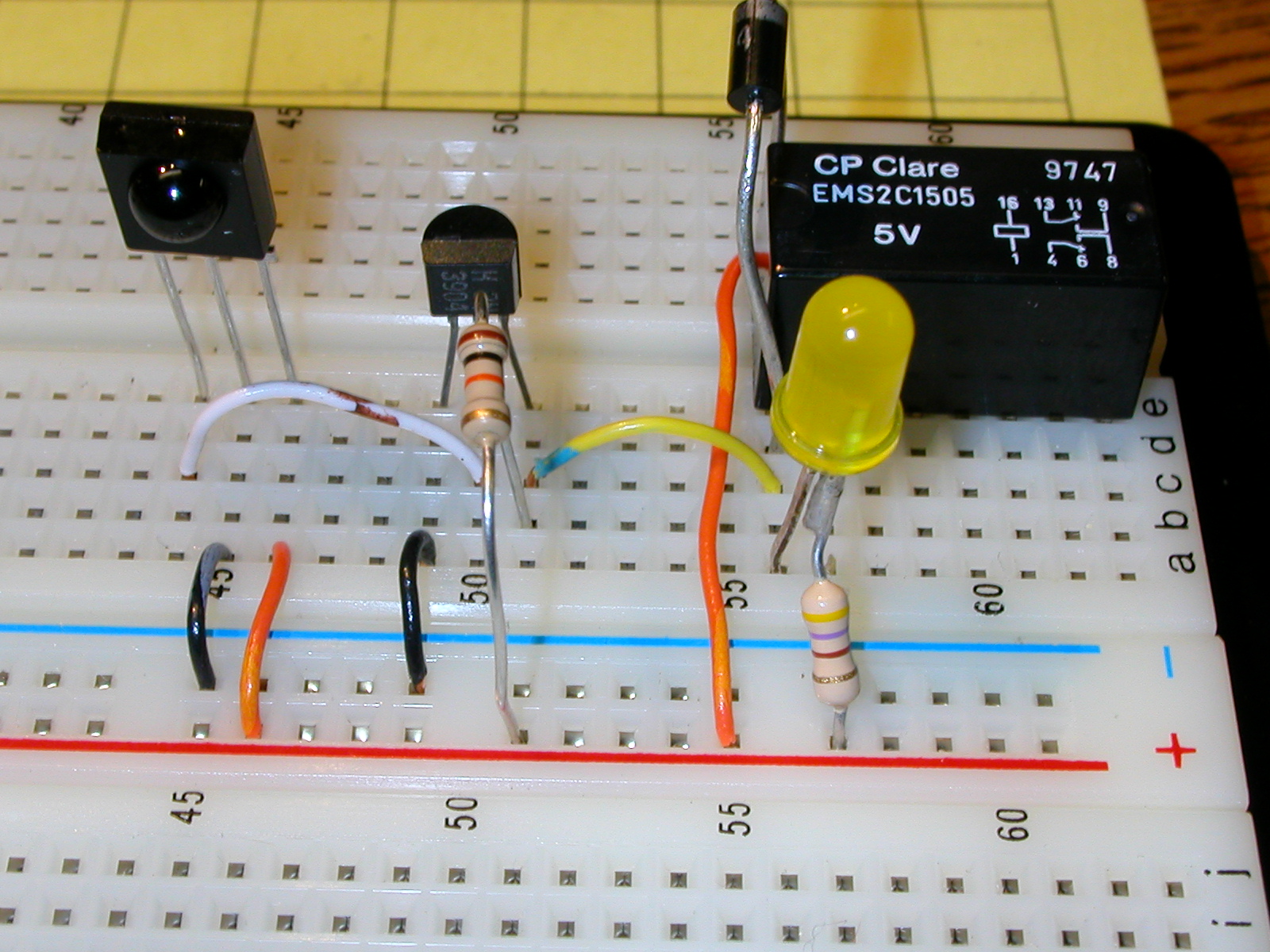
This photo shows the circuit on the prototyping breadboard. The relay opens and the LED goes out when 38 kHz IR pulses are detected.
Testing Reflection of IR
One of the advantages of bread boarding a circuit in this way is the opportunity to rapidly change things around to suit you. In the photo below the IR LED and the IR detector have been moved side by side by simply plugging them into an open area on the breadboard and extending jumper wires from their original positions.
As you might expect the setup above does not work as the IR detector is constantly flooded with IR from the LED. In the photo below a section of black tubing covers the sides of the LED so that IR can only be emitted to the front.
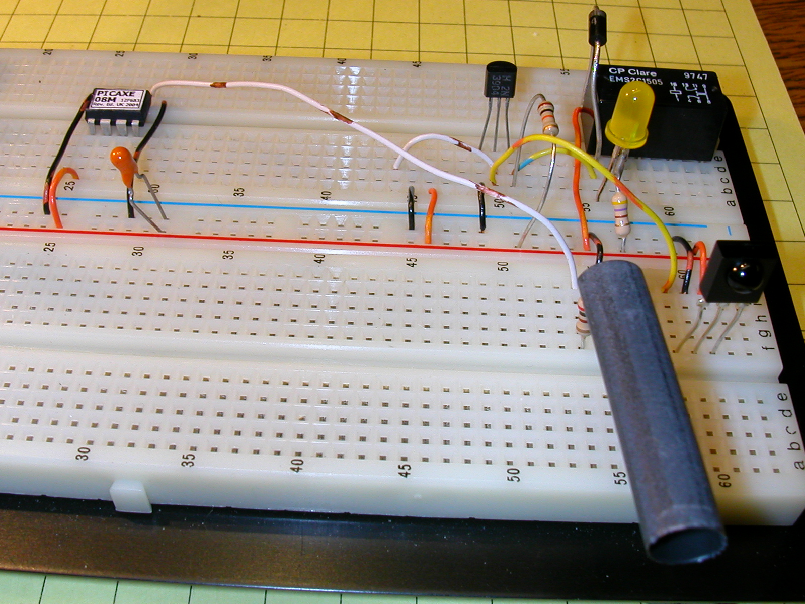
To give you an idea of the sensitivity of the circuit in this configuration I was able to consistently trip the sensor by moving my hand in front of it at a distance of 24". When I used a piece of white paper in place of my hand it worked well at 36". When I separated the IR detector and LED by building them on separate bread boards and aiming them towards each other I could detect breaks in the IR beam over more than 8 feet!
An Outdoor Installation
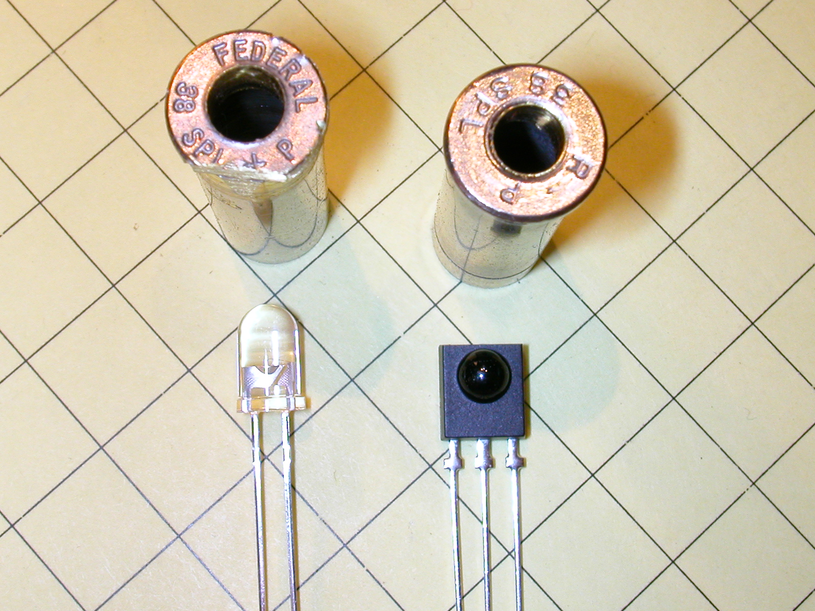
I have used this setup for nearly a year with a roadside crossing detector that I built for my railway. The IR LED is housed inside of an empty 357 shell casing. After you punch out the expended primer it is a simple matter to enlarge the hole to fit the LED. I found that a 13/64" hole works well. Similarly the IR detector is glued to the end of a shell casing that has had its primer hold drilled out to 3/16" to better fit the detector's lens.
In this photo you can see the two shell casings. The one on the left has been drilled out to 13/64" for the LED and the one on the right to 3/16" for the lens on the IR detector. Note that the edge of the left casing has been ground flat so that the two cartridges can be soldered together, one a bit forward of the other.
Here the devices are placed in their respective holes.
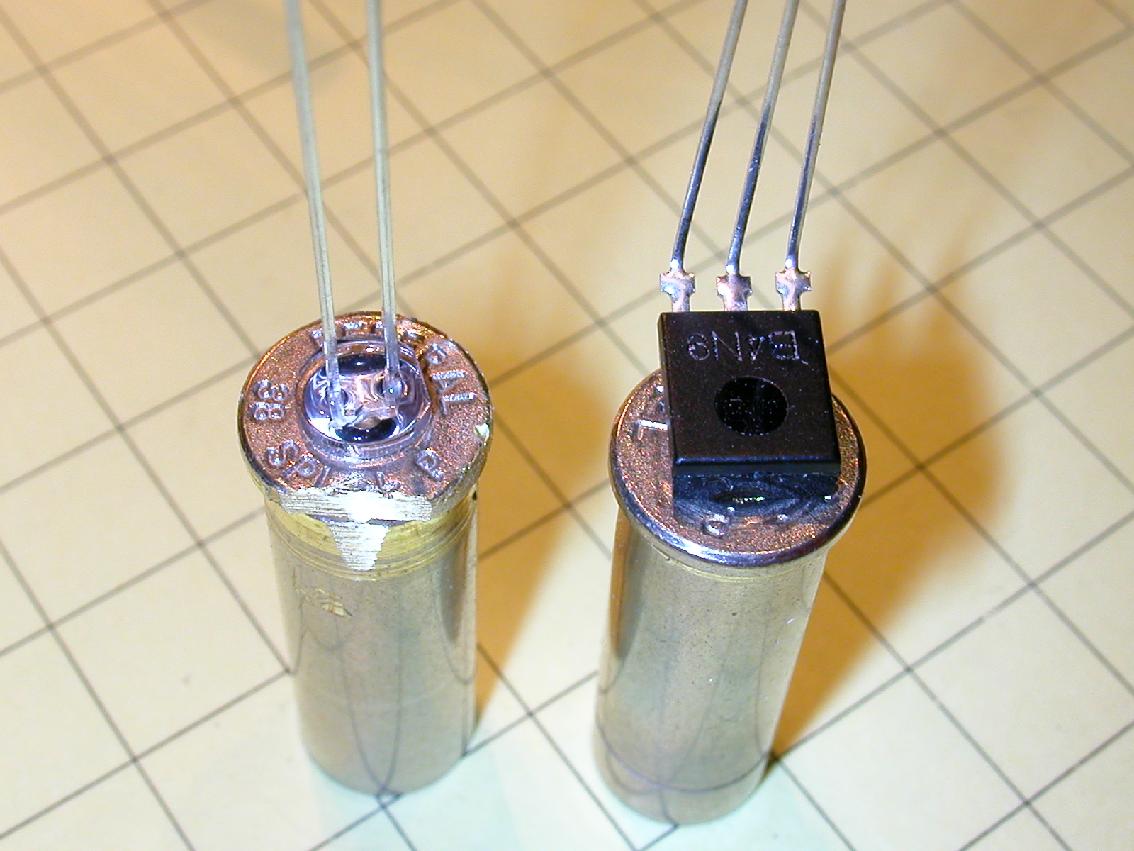
The IR LED's casing has been soldered forward of the one for the detector. This will help to isolate them so that no direct path for IR exists.
A 0.1 bypass capacitor has been soldered between the positive and negative leads of the detector. I found that adding this bypass capacitor improves performance when long wires are used between the detector and the other circuitry. I also soldered the negative lead from the IR LED to the center lead of the IR detector.
The back of the IR LED has been painted with several coats of black paint to add additional insurance that no IR emissions can escape the LED and get directly to the detector. If you skip this step you are likely to have problems - I sure did!
I used a 36" long piece of 4 conductor cable to connect the LED and sensor to the rest of the circuit. In the photo the yellow wire connects to the current limiting resistor on the LED, the brown wire goes to the negative terminal on the detector, the red wire to the positive terminal and the orange wire (somewhat hidden in the photo) to the output pin of the detector.
Since both the IR emitter and detector are inside of tubing you will not see the detection range that I had with the bread board example above but I still consistently trigger the unit with my hand at a distance of more than 12" and more than 18" with a piece of white paper.
The sensor and LED can be mounted inside of a building that is near the track or hidden in a similar structure. My only caution it to place it so that direct sunlight does not travel into the tube as it is likely to blind it. The best placement would be to have the sensor facing north.
Enhancements
So far we have treated the circuits for the IR LED emitter and the detector as separate entities. This is great if you are using the 555 to generate the pulses but a waste of available computing power if you are using the Picaxe 08M microprocessor. Rather than have the detector drive the relay directly it makes more sense to have the IR detector connected to an unused input pin of the Picaxe and have one of the Picaxe output pins drive the relay.
Once you do that the Picaxe has all of the information to control things. If there is interest there are some exciting things that can be done with this concept.
I think you will find this sensor to be an extremely versatile one and I hope you have a chance to give it a try. Please let me know if I can help!
| Parts list: 555
Oscillator
Picaxe based 38 kHz oscillator
IR Receiver
Miscellaneous
For those of you who would like to experiment with the Picaxe but don't want to bother programming it I will be glad to supply the Picaxe 08M programmed as in the example above at my cost. Please contact me via email (dave@davebodnar.com) for details I have given Radio Shack part numbers for the parts used in this article but you are likely to find much better prices from other vendors, including Hosfelt (www.hosfelt.com), Digikey (www.digikey.com), Electronics Goldmine (www.electronicsgoldmine.com), Jameco (www.jameco.com) and Glitchbusters (www.glitchbusters.com) - I have links to these and other vendors on my web page at www.davebodnar.com. |