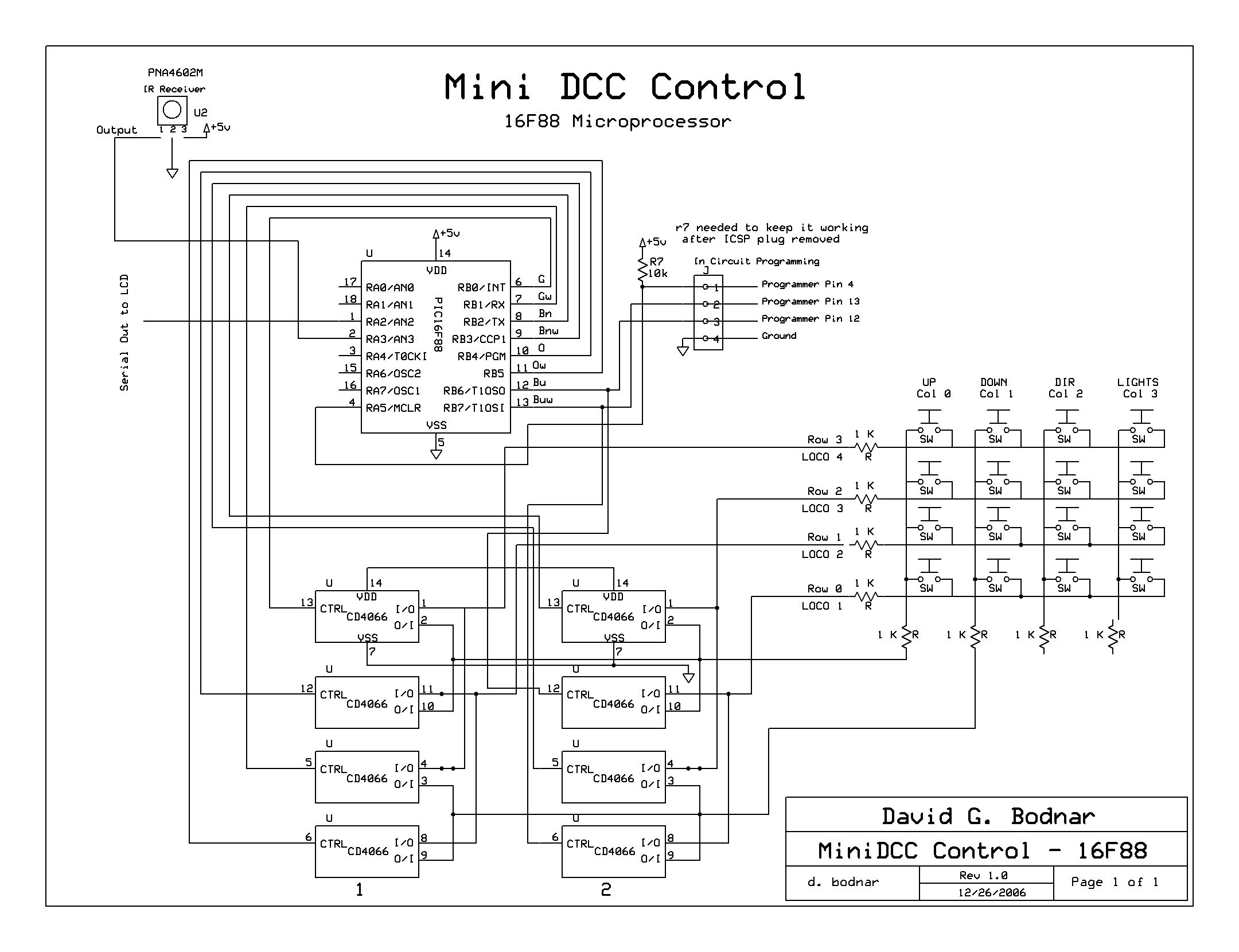
| IR Control / Configuration of 16F88 Controller Because
of a limited number of available pins on the 16F88 an infrared TV
remote control is being used to change settings on the controller.
The IR signal is received by the PNA4602M. It is made to react
only to IR signals that are modulated at 38 KHz, the frequency used
by a typical TV remote control unit.
These signals are decoded in the 16F88 and are used to set
variables, accelerate / decelerate engines and to initiate operation
of the controller.
|
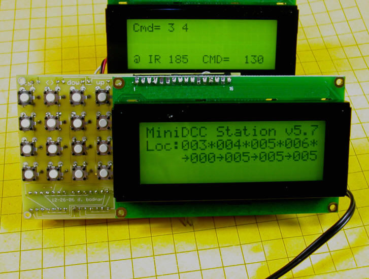
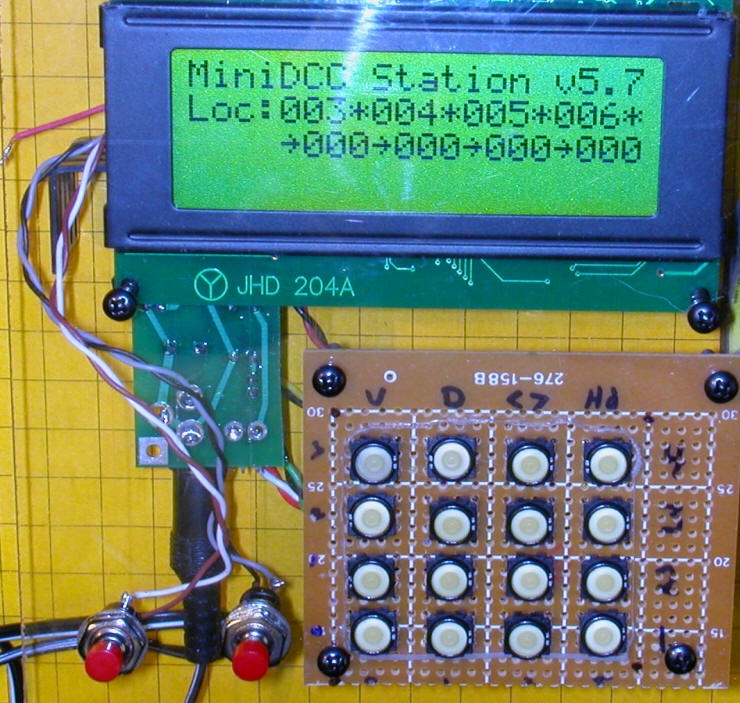
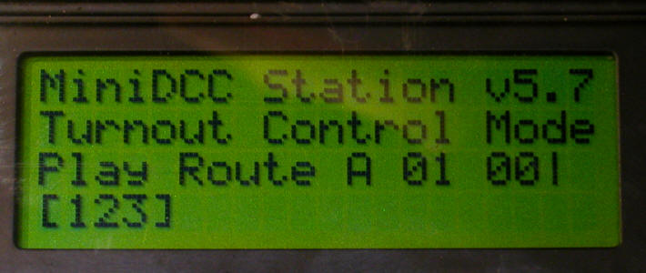
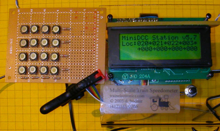
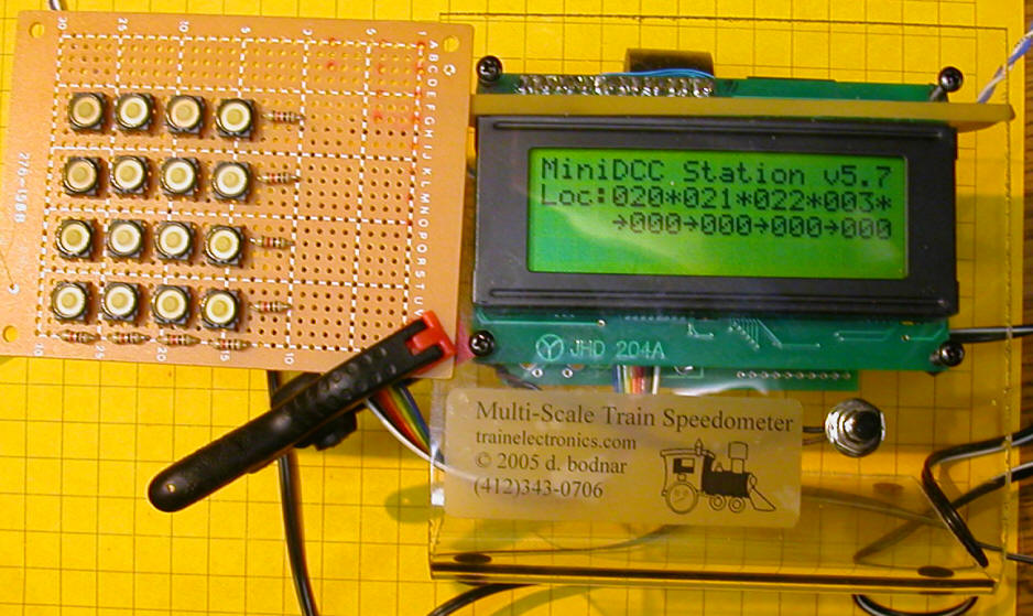
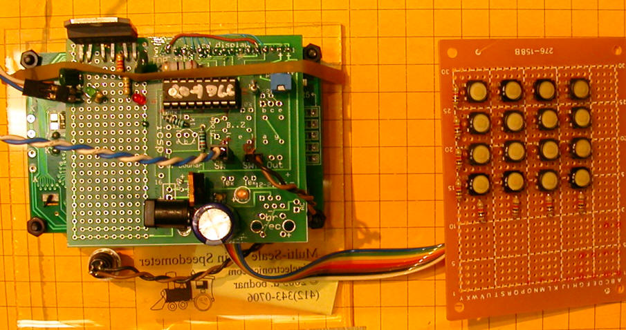
| Circuit Board Photos This is a view of the MiniDCC LCD
(front) and the PIC Controller LCD (back) and the 4 x 4 keypad
(left)
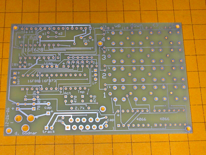
Here is the bare board, component side.
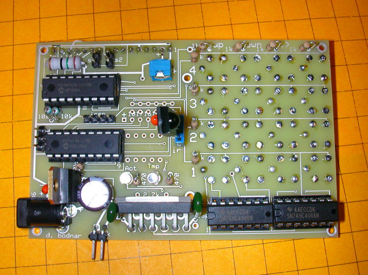
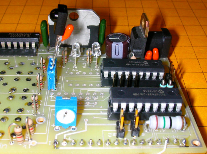
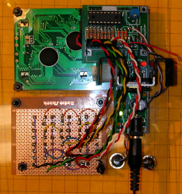
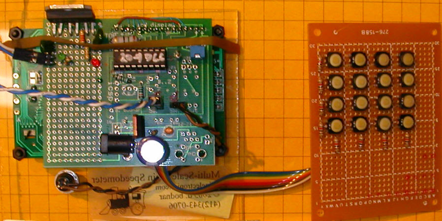
This is an overhead view of the component side with most
components mounted. The MiniDCC PIC is upper left, the PIC
Control chip is just below it, the IR sensor is in the center, the
18200 is bottom center and the two 4066's are bottom right - the
pushbuttons for the keypad are on the other side.
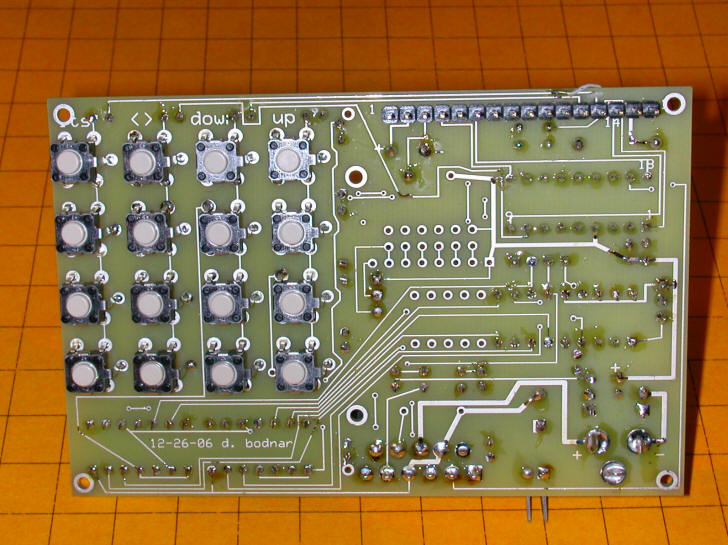
Here is a full view of the keypad side of the board. The
MiniDCC LCD plugs into the header in the upper right.
This is a close-up view of the component side.
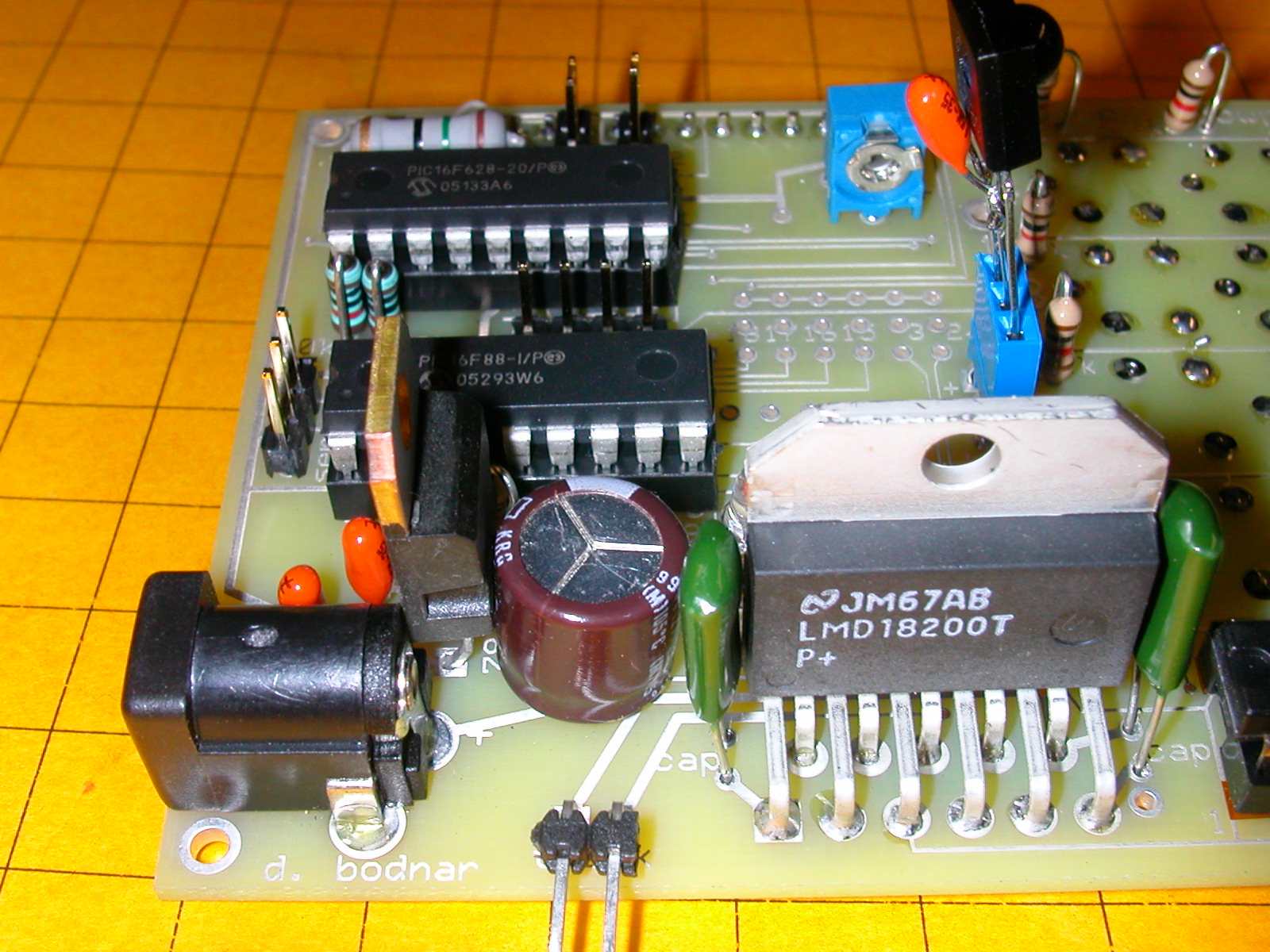
A close-up of the 18200 and power supply section.

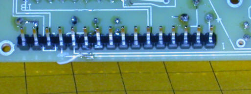
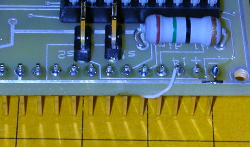
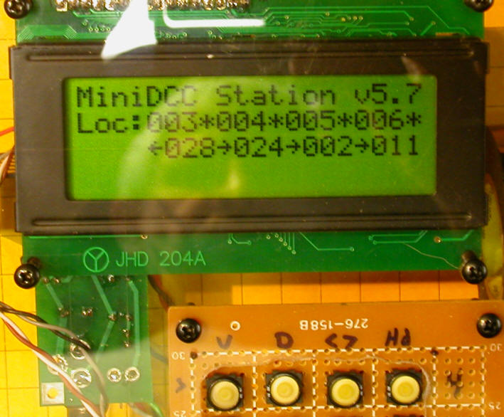
Only one piece of rework was necessary. I miswired the
connection between pin 14 and the headlight section of the keypad
matrix. The fix is in the two photos below. One error on
a board with all of these components is not too bad!
 |
| Test Code (PicBasic Pro)
Include "modedefs.bas"
cmcon=7 'allows you to use pins as digital rather than analog
ansel=0 'allows you to use pins as digital rather than analog
@ DEVICE PIC16F88, INTRC_OSC_NOCLKOUT, WDT_OFF, LVP_OFF, PWRT_ON,
PROTECT_ON, BOD_ON
OSCCON = %01100111 'MUST BE USED to set clock speed %01100111 =$67 =
4mhz
clear
Serial_out var PORTA.2
Ser_Speed con 188
rw0 var portb.0
rw1 var portb.1
rw2 var portb.2
rw3 var portb.2
cl10 var portb.4 ' 10
cl11 var portb.5 ' 11
cl00 var portb.6 ' 12
cl01 var portb.7 ' 13
cl30 var portb.0 ' 6
cl31 var portb.1 ' 7
cl20 var portb.2 ' 8
cl21 var portb.3 ' 9
sensor1 var porta.6 '15
sensor2 var porta.7 '16
sensor3 var porta.0 '17
sensor4 var porta.1 '18
IRin var porta.3
led2 var porta.7 'red LED
led var porta.4 'white LED 'pin 3
temp var word
temp2 var word
temp3 var byte
temp4 var byte
temp5 var byte
temp6 var word
temp7 var word
tempbyte var byte
x var byte
xx var byte
Delay var byte
Delay2 var byte
Vwhole var word
Vdecimal var word
Vwhole=2
Vdecimal=0
zero con 136
one con 128
two con 129
three con 130
four con 131
five con 132
six con 133
seven con 134
eight con 135
nine con 136
channelUP con 144
channelDOWN con 145
volumeUP con 146
volumeDOWN con 147
OK con 148
Menu con 224
ENTER con 139
digit var byte
SpeedStep var word
TempWord var word
TempWord2 var word
value var byte
temp0 var byte
temp1 var word
Train var byte(10)
xxx var byte
trisa.2=0
delay = 15 'was 35
delay2=12
trisb=0 'all of port b to output to drive keyboard on miniDCC
trisa.3=1
trisa.7=0
p_len var byte
steps VAR WORD
trisa = %11001111
Command Var Byte
IRpulse_length var word(13)
'clear
train(1)=0 'cl00
train(2)=2 'cl10
train(3)=4 'cl20
train(4)=6 'cl30
Train(5)=1 'cl01
Train(6)=3 'cl11
Train(7)=5 'cl21
Train(8)=7 'cl31
speedstep=5
'next line toggles all 4066's to initiate them - NEED IT!
for xx=1 to 8:high train(xx):pause 10:low train(xx):pause 10:next
'pause 200
again:
serout2 serial_out, Ser_Speed,["?f?c0"]:pause 200:serout
serial_out,Ser_Speed,["?f?c0"]:pause 200 '?c0 turns cursor off
serout2 serial_out, Ser_Speed,["?B40"]:pause 200 'set brightness of
LCD
serout2 serial_out, Ser_Speed,["MiniDCC Driver_test?nd. bodnar
12-2006?nVersion ",#vwhole,".",#Vdecimal]
pause 200
start:
gosub getir:
if command >=128 and command <=137 and command <> 136 and command <>
134 then
xxx=command-127
if xxx=6 then xxx=7
if xxx=5 then xxx=6
if xxx=4 then xxx=5
if xxx=8 then xxx=4
if xxx=10 then xxx=8
Serout2 serial_out, Ser_Speed,["?y0?x00Cmd= ",#xxx," ",#train(xxx)]
gosub TrainUp:command=0
endif
if command=OK then gosub All_Stop:command=0
if command = enter then goto GetRevSettings
goto start:
TrainUP:
for temp=1 to speedstep :high Train(xxx):pause delay:low
Train(xxx):pause delay:next temp
return
All_Stop:
for temp=1 to 35
for temp2=5 to 8
high train(temp2):pause delay:low train(temp2):pause delay
next temp2
next temp
return
GetIR:
low led
p_len=100
temp4=temp4+1
Serout2 serial_out, Ser_Speed,["?y3?x00@ IR ",#temp4," "]
Getstartbits:
Pulsin IRin ,0,IRpulse_length(0)
if IRpulse_length(0) < 200 then 'was 200 for 4 mhz clock
return
Endif
toggle led
for xx=1 to 12
pulsin IRin,0,IRpulse_length(xx)
next xx
displaybits:
if IRpulse_length(1) < p_len then 'was 100 for 4 mhz clock
Command.bit0 = 0
Else
Command.bit0 = 1
endif
if IRpulse_length(2) < p_len then
Command.bit1 = 0
Else
Command.bit1 = 1
endif
if IRpulse_length(3) < p_len then
Command.bit2 = 0
Else
Command.bit2 = 1
endif
if IRpulse_length(4) < p_len then
Command.bit3 = 0
Else
Command.bit3 = 1
endif
if IRpulse_length(5) < p_len then
Command.bit4 = 0
Else
Command.bit4 = 1
endif
if IRpulse_length(6) < p_len then
Command.bit5 = 0
Else
Command.bit5 = 1
endif
if IRpulse_length(7) < p_len then
Command.bit6 = 0
Else
Command.bit6 = 1
endif
if IRpulse_length(8) < p_len then
Command.bit7 = 0
Else
Command.bit7 = 1
Endif
If Command.bit7 = 0 then 'Bit 7 is one of the device bits
Command = Command + 1
Endif
If Command = 10 then
Command = 0
Endif
serout2 serial_out, Ser_Speed,["?y3?x10CMD= ",#command]
return
GetRevSettings:
digit=2
speedstep=0
high LED:pause 500:low LED
GetRevSettings0:
gosub getir
if command=0 then GetRevSettings0
if command > 137 or command < 128 and command <>139 and command <> 0
then
goto start: 'abort on non number 0-9
endif
if command=139 then GetRevSettings0
Value=command-127
if Value = 10 then value=0
if value=0 then high LED:pause 250:low LED
for tempbyte=1 to value:High LED:pause 100:low LED:pause 100:next
tempbyte
speedstep=speedstep*10+Value
digit=digit-1
pause 100:command=0
if digit=0 then
temp0= speedstep / 256
write 0, temp0
temp1 = temp0*256
temp2= speedstep-temp1
write 1, temp2
'gosub test4:
goto start:
endif
goto GetRevSettings0 |