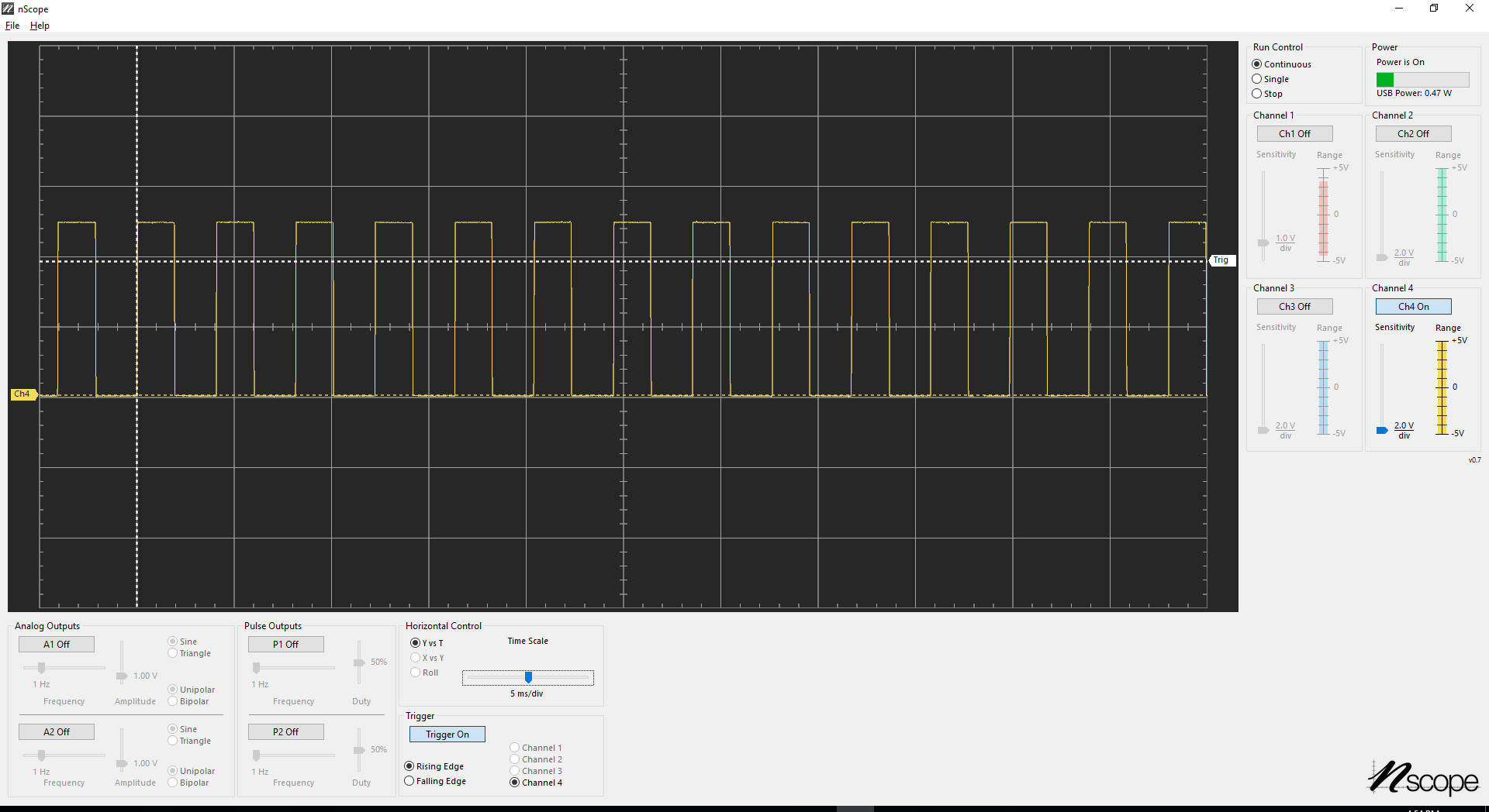
| This is a screen shot of PWM from the
Arduino setup shown below.
|
|
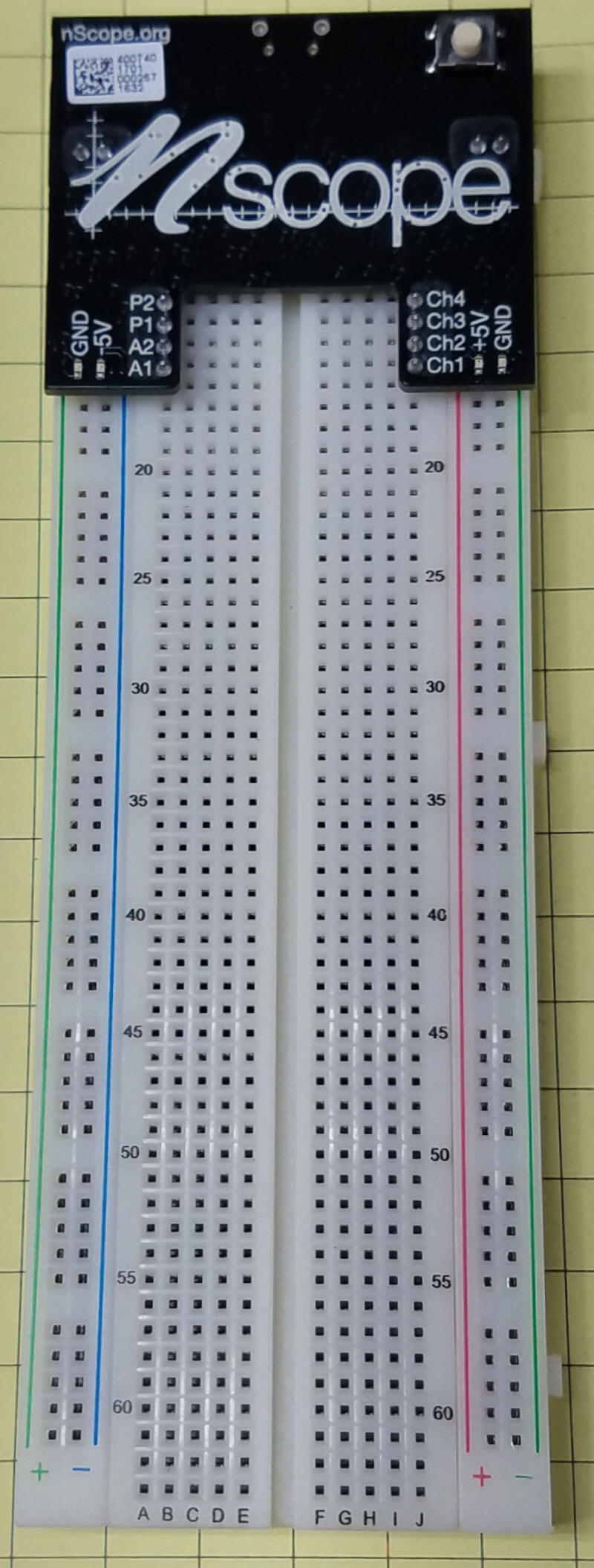
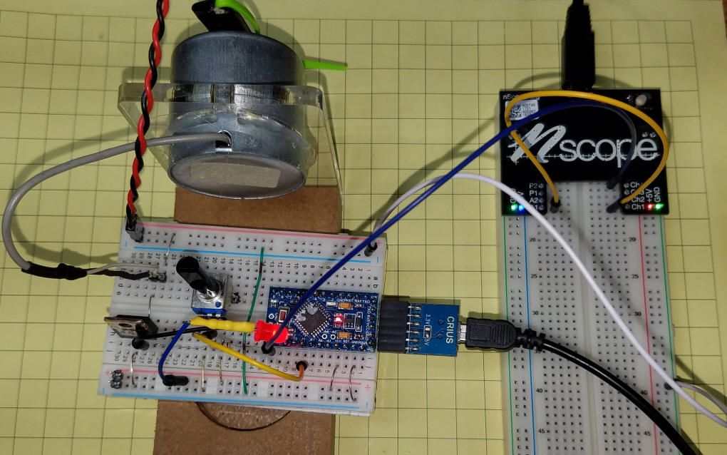
The nScope comes attached to a prototype board. It can easily be removed and moved to another board. The button in the upper right turns power (5 volts) on to the power rails on the left and the right of the board.
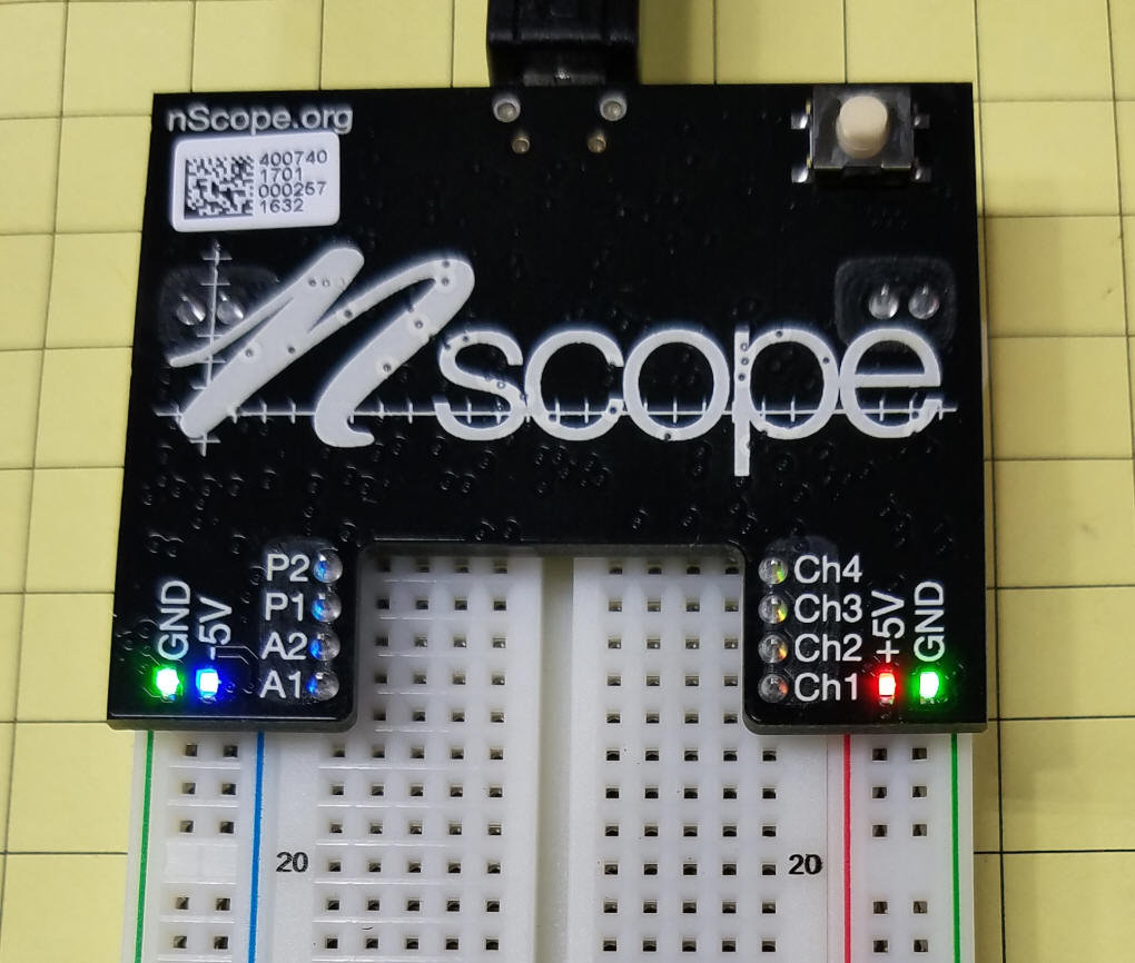
Here the USB cable has been plugged into the top of the board and the power has been turned on as shown by the RED and BLUE LEDs.
Here the nScope has been removed from the board. The pins to the left are outputs (P1 and P2 are PWM and A1 and A2 are analog outpots from the function generator.) The four oscilloscope inputs are to the right (Ch1 --> Ch4)
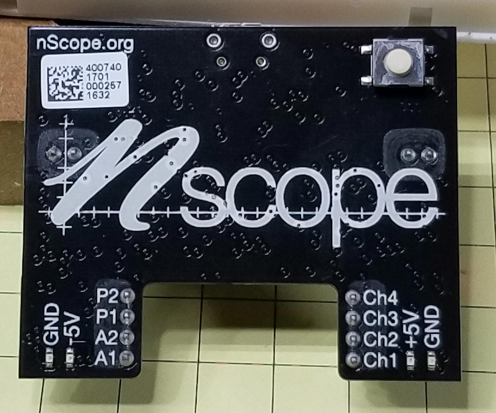
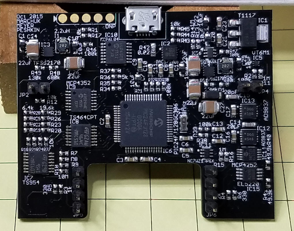
This view is the back of the board. The main processor is from MicroChip - 24FJ128. The USB socket is at top center.
This test setup was used to view PWM generated by the Arduino. The screen shot of the PWM output is at the top of this page.
|