Animate Your Layout With Sound and Light
revised 04-02-08
Animation on your garden railroad can take many forms. Most of us equate animation with movement but bringing things to life is not limited to movement alone. One of the most interesting and attention getting animations that we have installed at the new Phipps Conservatory garden railroad has no moving parts at all!
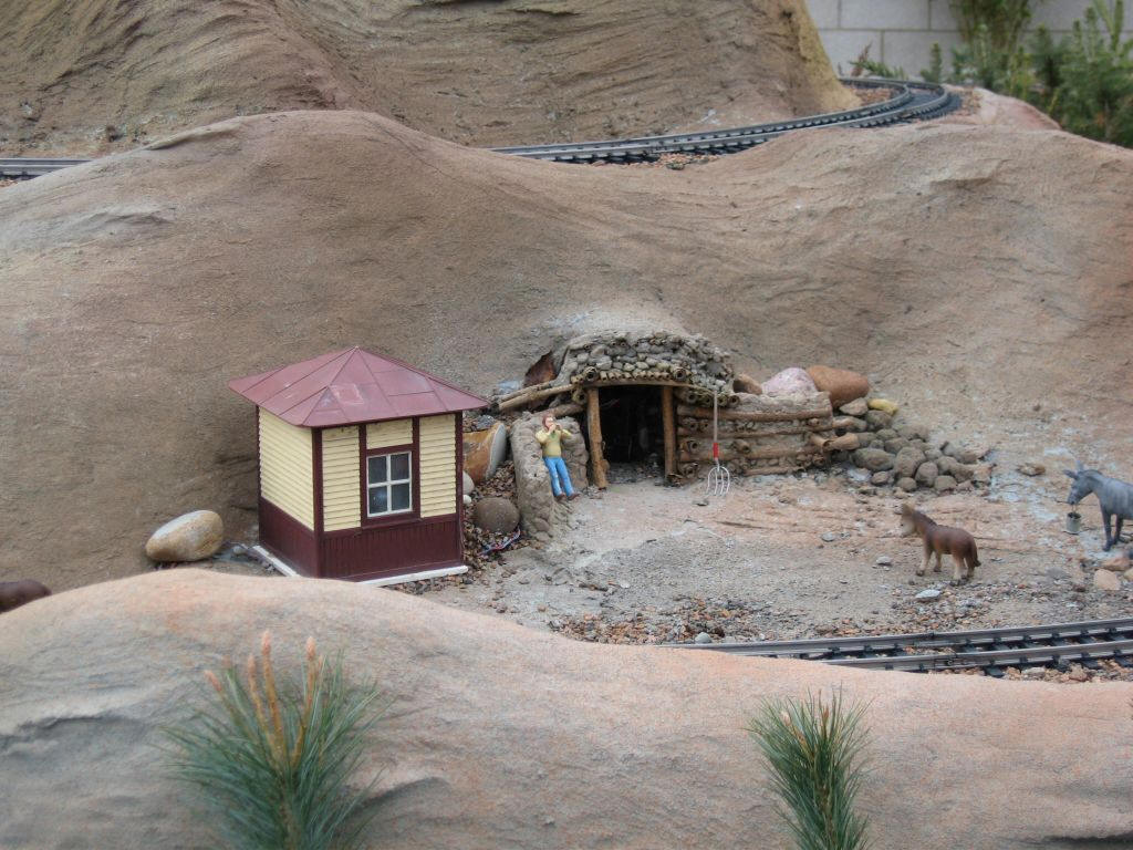
A small gold mine entrance has been carved into the side of a mountain. As the passenger train cruises past, a lone miner stands by the opening and yells out "Clear the area... Blasting in 10 seconds!" A short while later he shouts "Fire in the hole!" An instant passes before a bright flash emanates from the mine entrance to the accompaniment of a loud and thunderous explosion.
This animation has fascinated visitors as they try to figure out exactly what is happening. Some just catch a bit of the dialog and a hint of the flash gives them pause. More than a few wait for the train to come around again to trigger the event. Children have been seen refusing to leave until they can see it "one more time, mommy!"
Design Objectives
When the members of the Pittsburgh Garden Railway Society brainstormed about the design of this layout we envisioned a number of vignettes that would bring interest to the layout. Two of the animations, the outhouse and prairie dog town, were examined in an earlier article.
Once we decided that we would like to add a small prospector's mine to the layout we brainstormed ways to bring it alive. An explosion as the miner blasted deep within the mine was an obvious choice. Smoke and debris coming from the mine entrance would have been nice but there is no practical way to create such an effect that would run over and over, day after day without maintenance. We settled on having high quality sound effects coupled with a bright flash from within the mine. Our next task was figuring out how to do it.
Inexpensive (how about free?) Flash Units
I have experimented with adding flashing lights to my home layout for years. You may recall my article on building a solar powered Morse code beacon. This has been running on a tower next to my model ham radio shack for years, flashing out my call, N3ENM, over and over. A few years ago I took flashing lights to another level when I built a saloon & photo studio for the layout. I wanted visitors to periodically see a flash coming from within the photographer's studio. This was accomplished by placing a motion detector in one of the building's windows. When a visitor came by it triggered a recycled photo flash unit from a single use camera. The system worked like a charm for several months. Then the inevitable happened during a heavy rain storm. Water got into the circuitry and shorted some of the components. It was, however, a most fortuitous event! Afterwards the camera flash didn't go off when activated by motion but it flashed repeatedly every 3 seconds, over and over again. I decided to leave it that way just to see how long the flashing would continue. I didn't expect it to go on for too long, especially since I used the innards of a disposable unit. Much to my surprise and amazement it continued for nearly three years. In fact, it started flashing repeatedly in June of 2005 and is still going strong! Now that I had evidence that the flash units could last for a long, long time I decided to use one for the Phipps layout.
Single Use Camera Anatomy 101
The flash unit that I used was removed from a standard single use flash camera like these.

You can probably get one for little or no money by asking the local drug store or other film developing establishment if you can have a few for use on your railroad. Most are happy to oblige as they have lots of camera bodies left over after processing the film. They do send them back for recycling but I don't think anyone keeps track of them.
If you don't want to disassemble a camera, All Electronics sells the flash units for a few dollars, item # FSH-12.
DANGER! High Voltage!
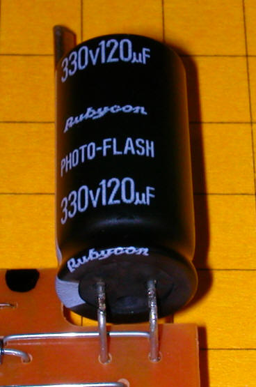
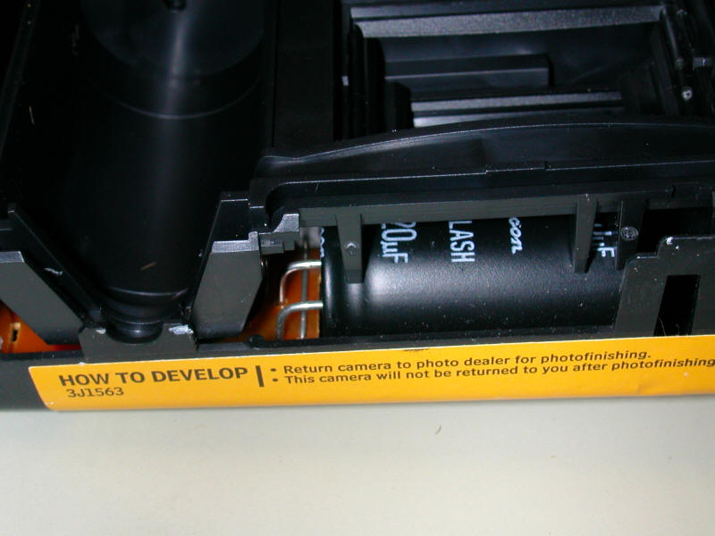
Whether you but a unit or decide to disassemble a camera to harvest its flash a few words of caution are in order. These little flash devices generate, and can store almost indefinitely, a 300-400 volt charge in their capacitor. I'll say that again... 300-400 volts! That is enough to really, really ruin your day if you happen to discharge it through your body. While it is not likely to kill you it will stimulate your nervous system and other body parts in ways that you are not apt to enjoy! I strongly suggest that you wear rubber or dry work gloves as you disassemble the camera. You also must discharge the capacitor, shown here, as soon as it is visible.
Disassembly
Follow these steps to disassemble the camera. Note that the specifics will vary from brand to brand.
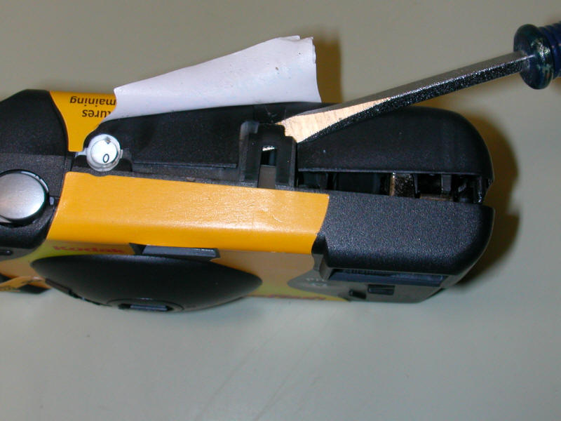
Remove enough of the paper covering from the plastic body of the camera to expose the tabs that hold it together
Look for latches on either side of the camera and / or on the bottom. Pry these open and separate the halves of the camera
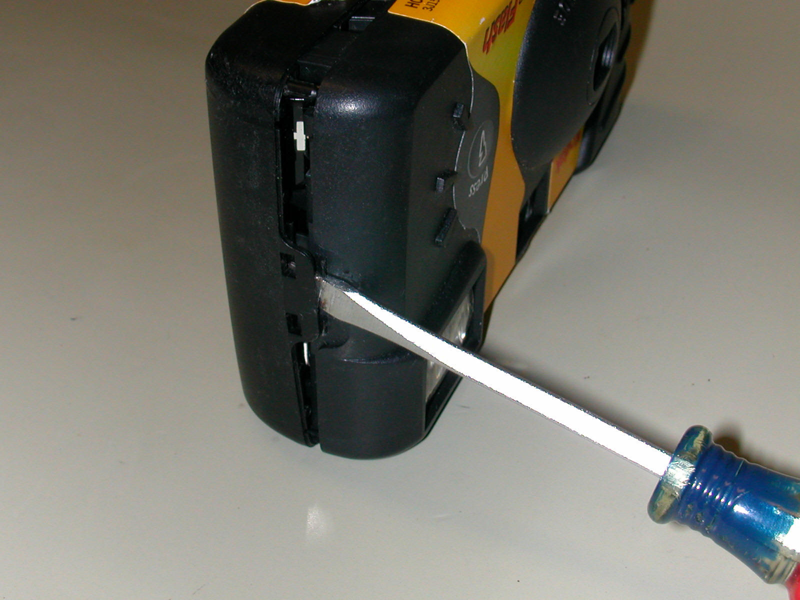
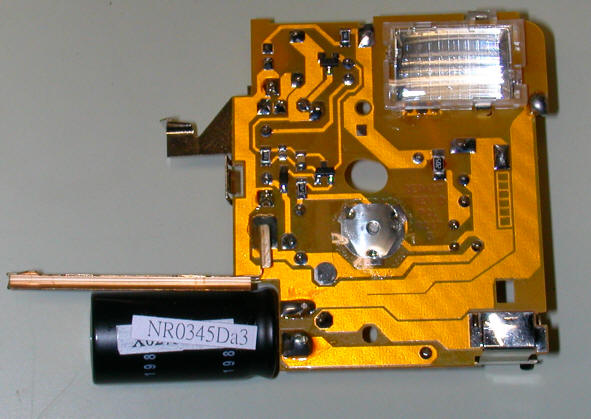
Keep an eye out for the flash circuitry and for the capacitor. It is a long cylinder with two wires coming from one end. Most are black or blue in color.
Once you have a clear view of the two wires coming out of the capacitor use the tip of a screwdriver with a plastic or rubber handle to short circuit them. You may see a large spark and hear a bit of a "bang!" as the electrons are set free.
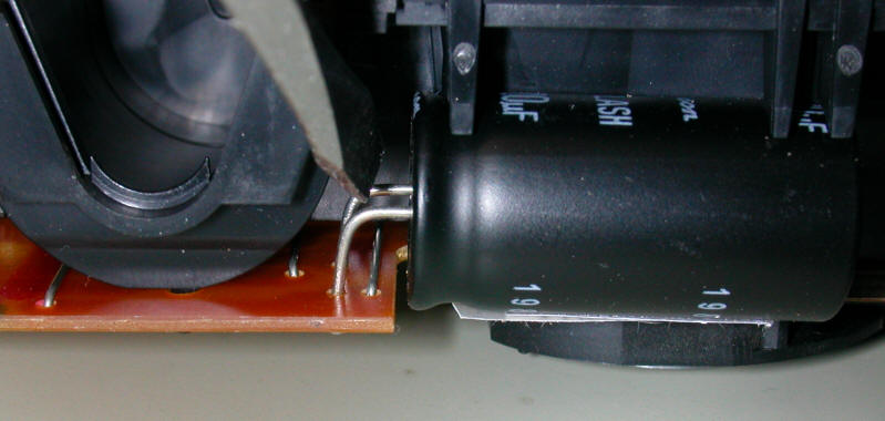
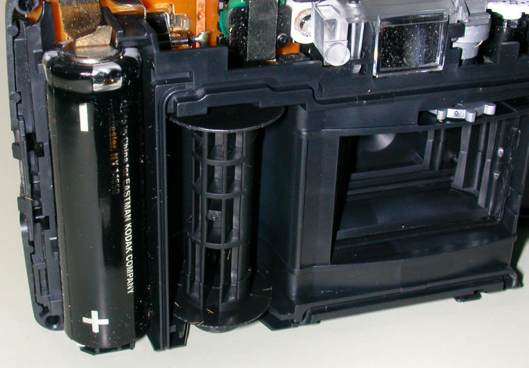
Next look for the AA or AAA battery that powers the flash. It is usually at the bottom of the camera. Take note of its orientation, jotting down which contact goes to the positive terminal and which goes to the negative. You will need this information later on. Remove the battery and short the capacitor again to make sure that it is completely discharged.
Look for plastic tabs that can be pushed to the side to remove the flash board. If any springs or other parts are attached to the board just pull them off as we don't need them.
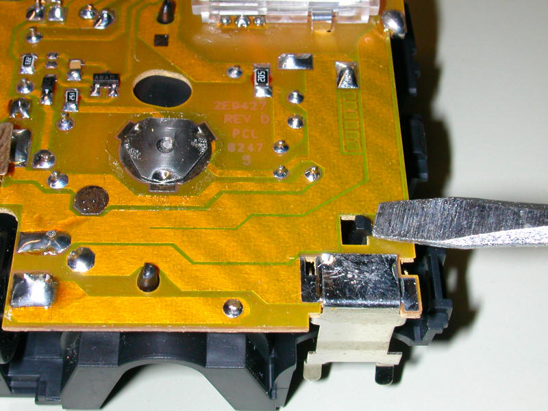
Once the board is free of the camera discharge the capacitor one more time just to be sure it is not holding a charge. Only then is it safe to hold the flash board in your bare hands.
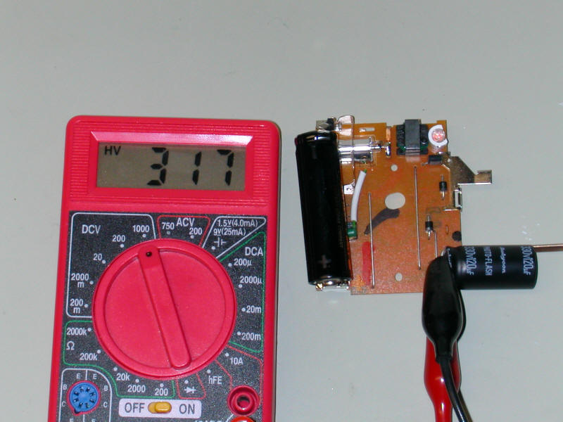
If you still doubt that such a small device that is powered by only one small battery can deliver such a jolt have a close look at the meter reading in the photo below. It is showing 317 volts DC across the capacitor!
Wiring the Flash
Four wires need to be soldered to the flash board and one jumper needs to be added.
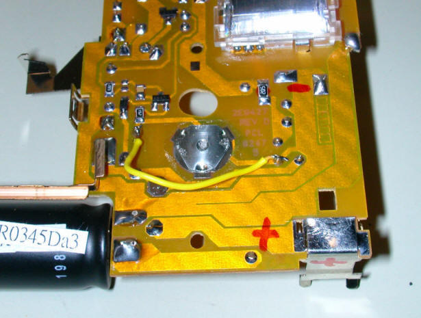
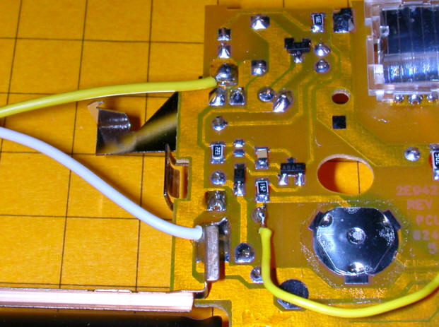
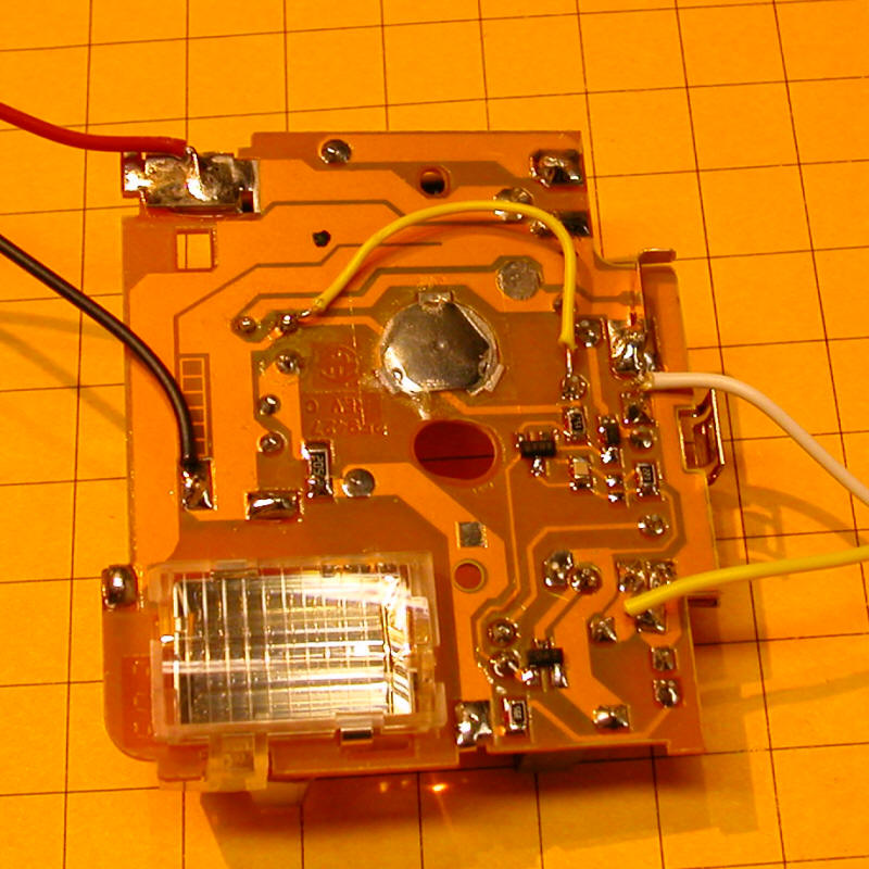
First we have to short out the contacts for the button that is used to charge the flash. The photo below shows where to jumper the Kodak camera I was working on. The yellow wire is the jumper that was added. It bridges the button, the large silver item in the center of the photo. If you are working with a different style of board just trace the contacts under the charge button and solder a jumper between them. Making this modification causes the flash to begin charging the capacitor as soon as power is connected.
Next we need to solder wires to the two battery contacts so that we can use an external power supply. Hopefully you made note of the way the battery was inserted in your camera when you disassembled it. Solder a length of red wire to the positive terminal and a length of black wire to the negative.
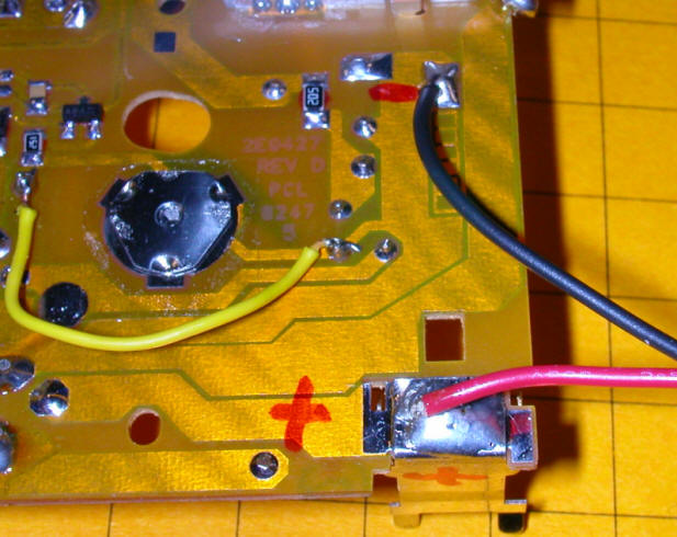
The last connection is to the trigger contacts. Solder a length of wire to each contact.
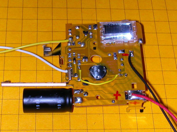
Here is one of the Kodak boards with all of the wiring done.
Power for the Flash
The biggest hurdle in using these recycled flash units is supplying them with power. You will recall that the only power supply for the camera is a single AA or AAA battery that delivers 1.5 volts. These boards are designed for this low voltage supply and using anything much above 2 volts tends to fry them. Since we want the flash to operate for a long time we need to find a way to supply power from a continuous source rather than from a battery. I thought this would not be a big deal until I put an ammeter on the flash and examined its power requirements. When the flash begins to charge it draws more than two amps! That is a remarkable amount of power to pull from a small battery. More significantly I discovered that it is no mean feat to make a 1.5 volt / 2 amp power supply.
My first attempt was to use a variable voltage regulator. An LM317 can provide voltages ranging from 1.2 to 25 or more volts. The problem is not the voltage but the current that the flash needs. If you are supplying the LM317 with 12 volts and are only using 1.5 volts for the flash the rest of the energy that goes into the regulator has to be dissipated as heat. Even with a large heat sink and a fan the LM317 quickly overheated. If you feed the LM317 with a 5 volt source it will work as there is much less of a voltage drop and less energy to dispose of. Unfortunately that was not an option for me.
At the Phipps layout I only had one source of power. This was from a connection that was used for lighting and other animations and it provided nearly13 volts. I had to come up with a way to get rid of quite a bit of excess energy. I tried a large wattage resistor but it, too, got way too hot to be safe. A voltage divider consumer too much energy after the flash charged. I finally settled on a using a string of sixteen 3 amp diodes wired in series. As you may know diodes will drop the voltage that passes through them by approximately 0.7 volts per diode. A series of 16 diodes drops the voltage by 16 x 0.7 = 11.2 volts. The input voltage is close to 13 volts giving me a consistent 1.8 volts to the flash unit. The diodes get hot just like the resistor and voltage regulator but the number of diodes and their large combined surface area seem better suited to radiating the excess heat.
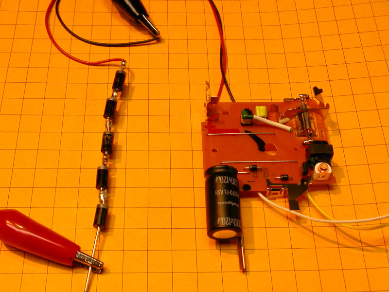
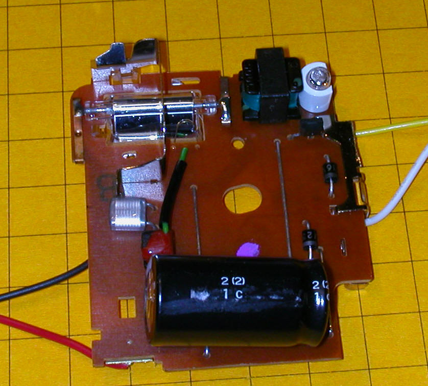
Here the flash unit is being tested. The red and black clips are connected to a 5 volt power supply. Since we only need to drop the voltage from 5 volts to 1.5 volts a string of just five diodes is needed for this test. One more word of caution. When testing avoid touching any part of the board including the trigger wires! The trigger wires don't carry the full voltage but there is enough there to give you a tickle! Continue to work with insulated tools and gloves when the capacitor is charged. If in doubt don't touch anything! Disconnect power and short the capacitor before touching any part of the unit.
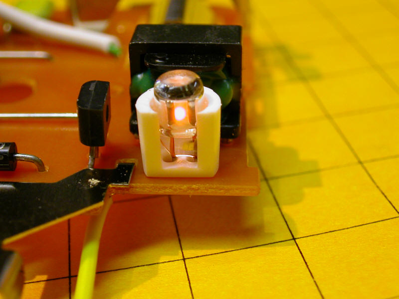
This close-up shows the Kodak board's "ready light". It glows when the capacitor is charged and the flash is ready to go. Some boards use a LED. This one uses a small neon bulb.
The last step in preparing the board is to remove some of the parts that extend from the board to make it more compact.
I also carefully bent the capacitor over so that it no longer stuck straight out.
A quick run through the band saw to cut the camera case in half gave me an enclosure for the flash unit. A bit of black tape to seal up the side and it was ready for use!
.JPG)
Firing the Flash
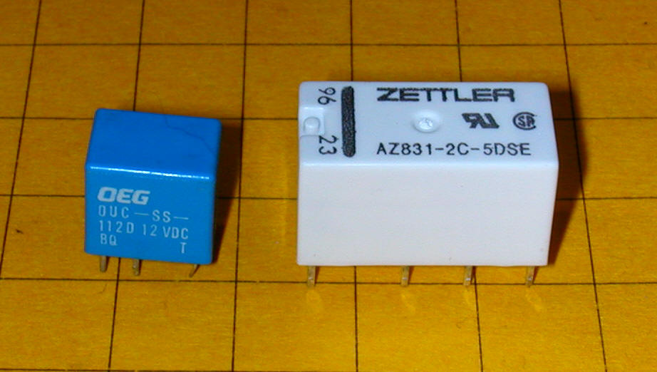
The flash is triggered by briefly connecting the two wires that we soldered to the trigger contacts. These wires carry a fairly high voltage so we can't use a normal transistor as a switch to set off the flash. I have successfully used triacs to fire these units but the type of triac that is needed varies from board to board so I have settled on using a small relay that will work with virtually any of the boards. This is easily incorporated into the microcontroller based circuit that will be the brains of the animation.
Any 5 volt relay can be used to trigger the flash. Here are two examples. I used relays that will fit into IC sockets as they are the one component of the system that could fail and I wanted to make them easy to replace.
High Quality Sound
Once the flash had been identified and made ready the next hurdle was finding a way to supply high quality sound that didn't distort at high volume. This would be for the two mine announcements and the explosion. I have used inexpensive digital recorders for a number of projects including the squeaking door on the layout's outhouse. Some experiments showed that trying to reproduce highly intelligible voice at high volume was beyond the capabilities of these boards.
I knew that an MP3 player had the capacity to produce quality sound but I needed one that I could easily interface to the microcontroller so that it could accurately synchronize the sound with the flash that was to accompany the explosion.
Rather than hacking a consumer MP3 player I decided to use a device that is designed to be controlled by microcontroller such as the PICAXE.. The board I chose to use is called VMUSIC2 and is available from a number of sources for less than $50.00.
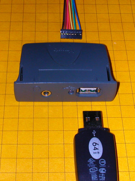
The VMUSIC2 module is less than 3" wide. The interface cable (only a few of the wires are used) and a standard USB memory stick that stores the MP3 sound files are also shown in this photo. A set of speakers plugs into the connection on the left side of the VMUSIC2.
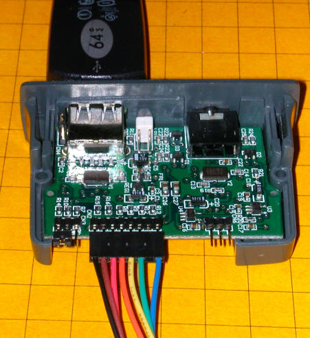
Removing the cover shows the electronics inside.
This board has a number of characteristics that make it ideal for this and other railway projects:
It can play any MP3 file in full stereo or monaural - music, sound effects, voice or a combination of the three
It uses a standard USB memory stick for storage (this really makes things easy!)
The only limit to the length and number of files it can play is the storage space on the memory stick
Sound files can easily be added or changed by inserting the memory stick into a computer
It connects to the microcontroller using a standard RS-232 serial interface
Sound output is by a standard 1/8" stereo headphone jack that can be fed directly to an external amplifier
Commands to Operate the Sound Module
The operation of the VMUSIC2 module is quite simple. Once
it is connected to the microcontroller, a PIC 16F684 in this case, all the
microcontroller has to do is send serial commands to play a particular clip.
To simplify the programming I saved all of the MP3 files with very short names.
The file that says "Clear the area... blasting in 10 seconds" is called 3.mp3.
The file that says "Fire in the hole!" is called 1.mp3, and the explosion
is 2.mp3. To play the first file the command
SEROUT Serial_out, 2, ["vpf
3.mp3", 13]
is executed. This program line sends the command "vpf 3.mp3"
to the VMUSIC2 via the serial cable at a speed of 9600 baud. The "2" in
the command sets the speed to 9600 and the "13" sends a carriage return at the
end of the command to indicate that the command is complete.
The "vpf" command tells the VMUSIC2 to play the file that follows the command. Other commands include:
Play all tracks - "w3a" plus a carriage return
Stop track - "vst" plus a carriage return
Skip to Next Track - "vsf" plus a carriage return
Skip to Start of current Track - "vsb" plus a carriage return
Pause - "e"
Resume (after pause) - just a carriage return
Set Volume - "vwr",$0B,vol_right,vol_left," plus a
carriage return
where 0 is the maximum volume and 254 is the minimum
Visit the Vinculum web site for more information on using this device.
Connecting the VMUSIC2 module to the PIC or PICAXE is very straightforward. The schematic shows the PIC16F684 microcontroller connecting to the flash relay, the VMUSIC2 sound module and a reed switch that triggers the mine animation. The PICAXE 14M works equally well in this application.

Schematic Notes
|
Software
|
| Program Notes The version of BASIC used by the PIC is very similar to that used by the PICAXE.
|
Making It Loud!
The VMUSIC2 module is not designed to drive a speaker directly. The output that normally goes to headphones can be sent to an amplifier from a recycled set of computer speakers. This provides more than enough volume to be heard when used with an outside layout.
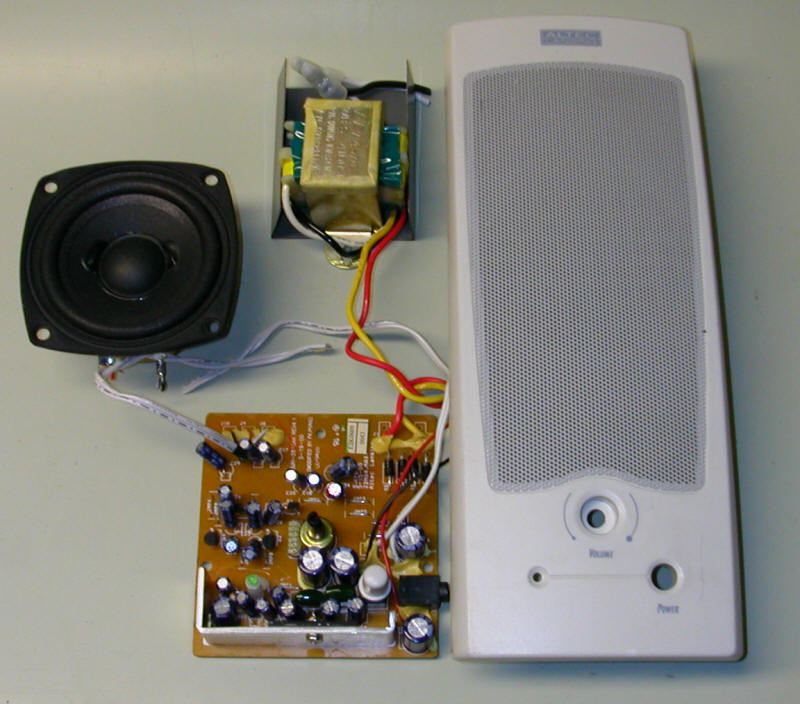
In this photo you can see the amplifier board (bottom center) and one of the two speakers. The other speaker is still in the plastic enclosure on the right. The AC transformer at the top is not needed as we will supply the amplifier with DC power.
Putting It All Together
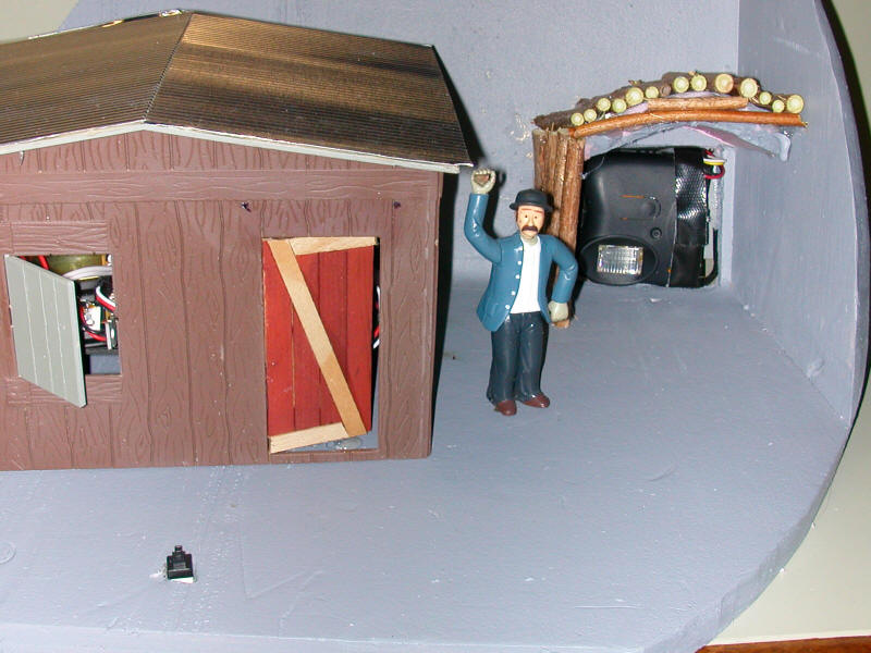
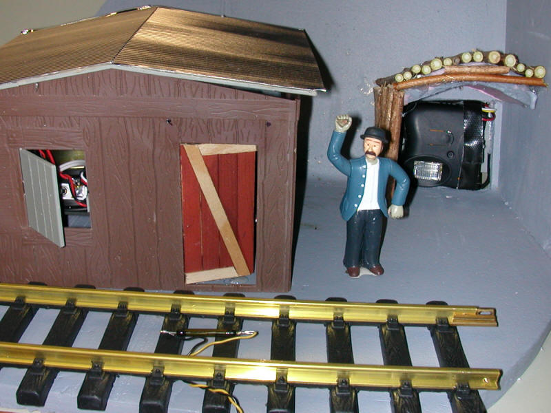
The flash unit is placed a few inches back inside the entrance to the mine. The other components are inside of a miner's shack next to the mine portal. A four wire cable connects the two.
This photograph is of a prototype of the mine explosion that I put together for testing. The flash unit can be seen inside of the mine entrance to the right. The trigger button is in the foreground.
The audio amplifier is at the top next to the VMUSIC2 module. The USB memory stick is labeled "64" as it has a 64 meg capacity.
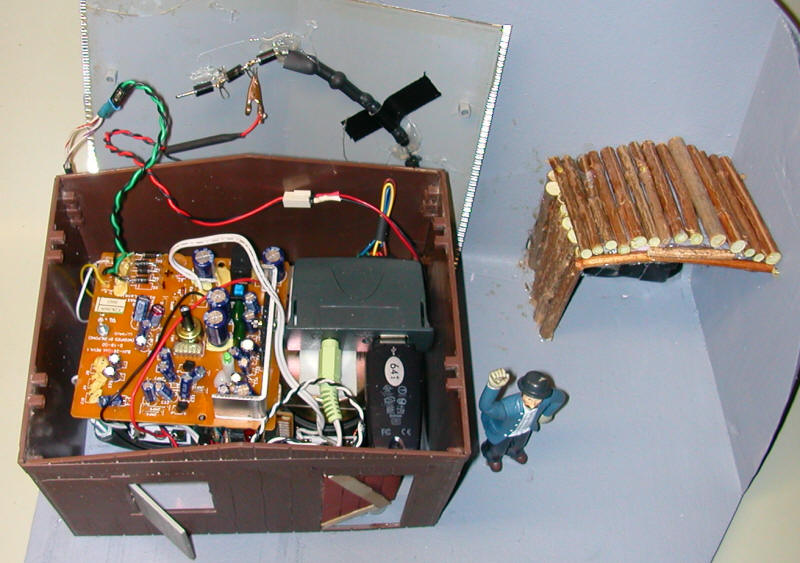
Here you see the two speakers facing downward. The microcontroller board is mounted on the side of the speakers. The entire unit easily fits within a small building.
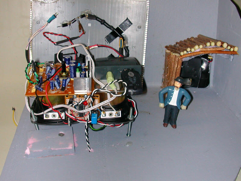
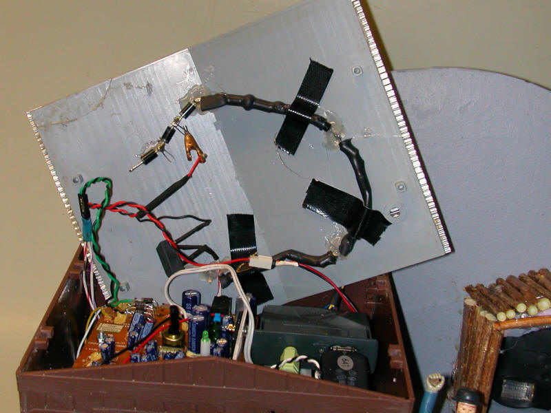
The 16 diodes that are used to supply 1.5 volts to the flash unit are attached to the inside of the building's roof. This gets them out of the way and allows them to radiate heat through the roof.
A reed switch is placed between the rails of the track by the mine. A magnet is glued to the bottom of the locomotive so that the animation starts when the train passes. The first sound clip "Clear the area, blasting in 10 seconds" gives the train time to get completely past before the explosion.
This video shows what happens when the unit is triggered.
Right click on the image below and select "Play"
Other Applications
The flash unit could be used in a number of places. As noted earlier it is a natural to include in a photo studio. I am sure that there are other places, such as industrial buildings or a mad scientist's laboratory, that you would find its flash to be appropriate.
The VMUSIC2 module can supply high quality sound for any number of applications. Because it can store literally hundreds of different audio files the microcontroller can easily be programmed to deliver random or sequential clips. This would allow you to have a variety of announcements and/or sounds coming from a station or other building.
That fact that it supports two stereo audio tracks means that you can use one VMUSIC2 board to supply different sounds to two different buildings. This can be done by putting one speaker from a stereo sound system in one building and the other speaker in a different one. You can create sound files for one building that only use one of the stereo channels and those for the other building on the other channel. The possibilities are endless!
I showed a variation on the VMUSIC2 module control system a the East Coast Large Scale Train Show that allows you to trigger sounds with a small hand held remote control unit. Sounds can also be activated by strategically placed reed or push button switches. This may become the focus of a new controller and yet another article. Please let me know if this is something that might interest you.
Speaking of editing sound there is an excellent audio editing program that is available at a great price, free! The audio editing program that I use is called Audacity and can be downloaded from http://audacity.sourceforge.net/download/. Giving instruction in the program's use is beyond the scope of this article but suffice it to say that Audacity is able to do just about anything you might need to do with audio files.
You can find thousands of free sound files on the Internet. My favorite site is the Free Sound Project. You need to register to download sounds but it is painless and there is no cost. Train sounds abound!
This animation project was great fun to put together. It is also great fun to see the smiles come to visitors' faces when they see it in action. Give it a try, I think you'll like it!
Please let me know if I can help.