| Introduction Many different crossing signals are available for model railroads. Some of them flash realistically but many do not. The worst of these don't even attempt to flash one light on while the other is off and visa versa. Even the ones that flash with some degree of realism don't allow for much control or modification of the flashing rate and when the signal is on or off. Dozens of manufacturers market crossing signal flashing controllers. In spite of the vast array of other controllers that are available I believe that another entry is appropriate as this device brings many more options and much more flexibility to the table. In its most basic mode the unit alternately flashes each crossing light bulb or LED for 1/2 second. Its more advanced modes use one or more trigger inputs and one or two potentiometers to adjust its behavior. Since it is software based it can easily be modified to do many more things than those that are installed at this time. Construction of the crossing controller also gives those of you who might have been looking for a simple soldering project a good reason to heat up the iron and practice. |
|||||||||||||||||||||||||||
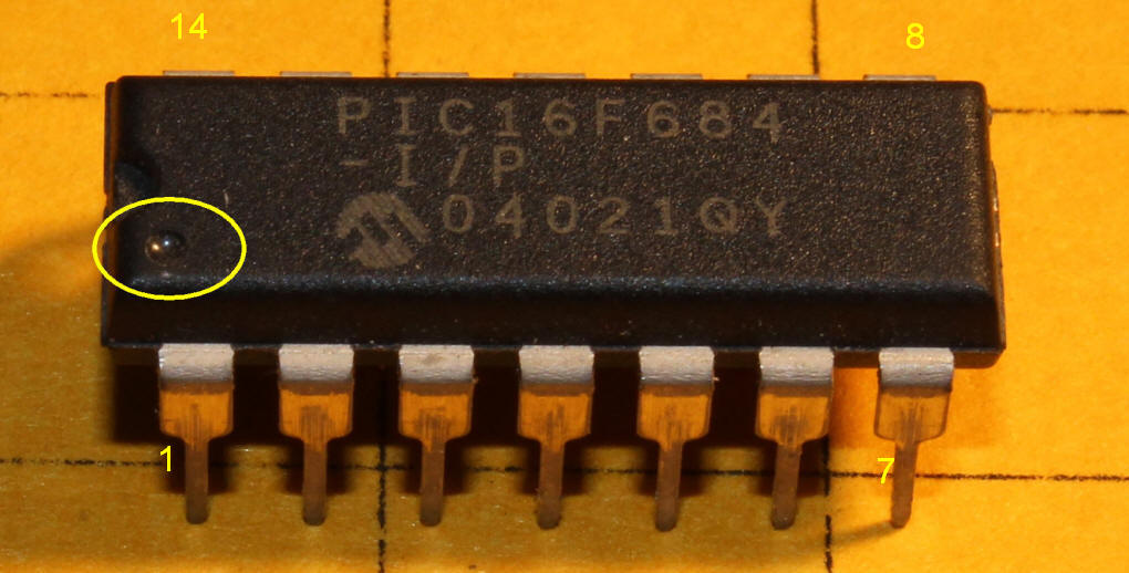
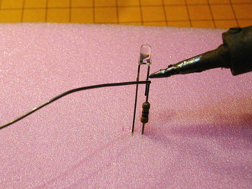
| Basic Operation The flasher is composed of a pre-programmed 14 pin microcontroller that has been configured to flash two LEDs in a number of different ways. The simplest configuration only requires that you connect pins 1 and 14 to a source of 3.5 to 5.0 volts DC and pins 5 and 6 to two LEDs. The only other parts that are needed are two current limiting resistors. Parts:
Construction:
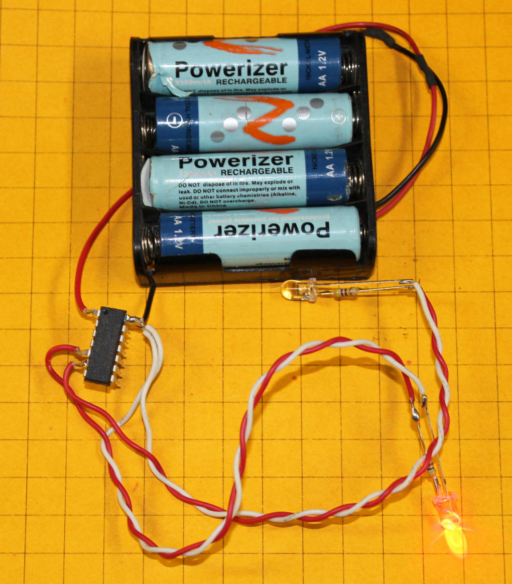
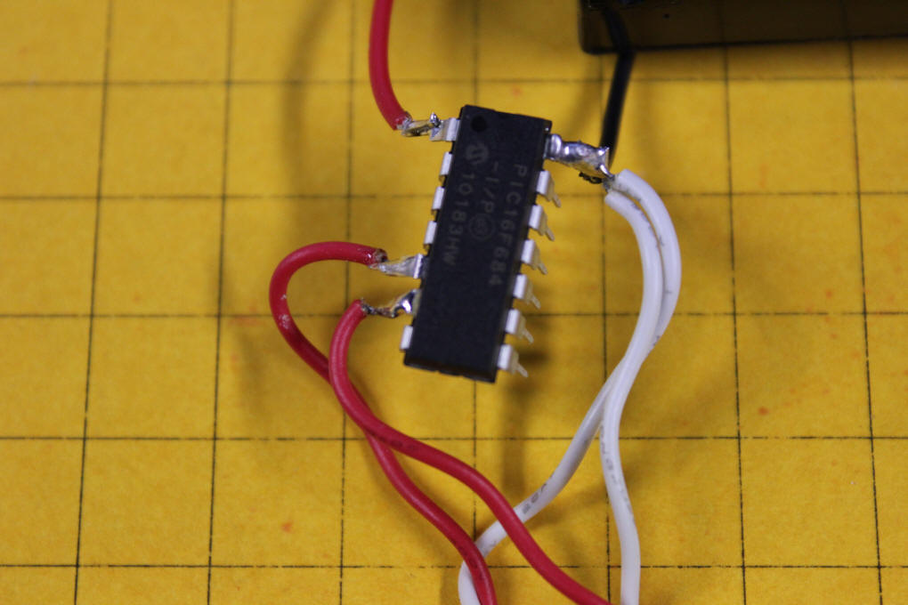
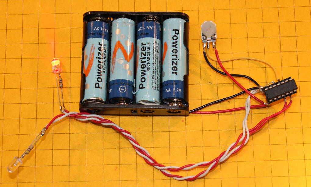
By using only four pins on the chip the LEDs flash alternately every 1/2 second. This photo shows the wiring described above done directly on the pins of the 14 pin chip. Note that the LEDs are connected to long leads to make it easier to get them into a crossing signal. The leads could easily be several feet long if needed. The battery pack is made up of four 1.2 volt rechargeable cells that give a total of 4.8 volts. DO NOT use a four pack of alkaline cells as they put out 1.5 volts and the 6 volt pack will fry the microcontroller in short order!
This close-up shows that pins 1 (upper left), 5, 6 and 14 (upper right) are the only pins that are used. Note the small dot next to pin #1
|
|||||||||||||||||||||||||||
| Variable Speed The behavior of the flashing LEDs can be changed by using other pins on the flasher chip. For example, if you connect pin 11 to ground (the negative terminal on the batteries) the speed of the flashing can be varied by connecting a potentiometer to pins 10, 1 and 14. Parts
Construction:
This photo shows this wiring done on a socket that is holding the 14 pin chip. Functionally it is identical to soldering to the chip but allows you to move the chip from socket to socket to experiment with different modes. The potentiometer is on a short length of cable. If you look closely you should also see a small piece of wire going from pin 11 to pin 14. Pin 11 is the one that selects the potentiometer speed option when it is connected to ground. The two methods of wiring these chips are not meant to demonstrate "best practices" by any means but are designed to show how minimal the wiring can be to get the system working. Ideally the circuit board shown later in the article or a small piece of perf-board should be used to hold the chip and other components.
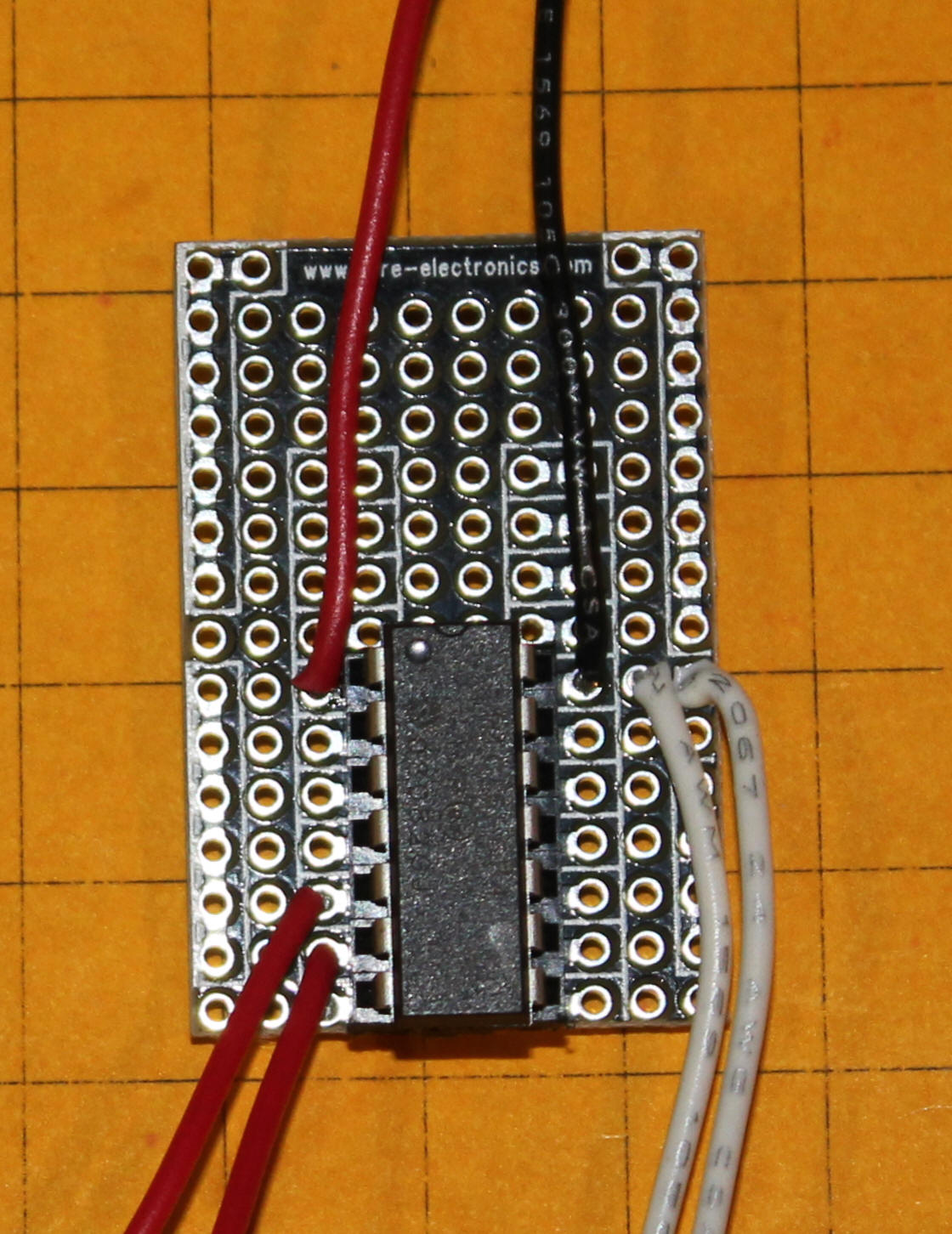
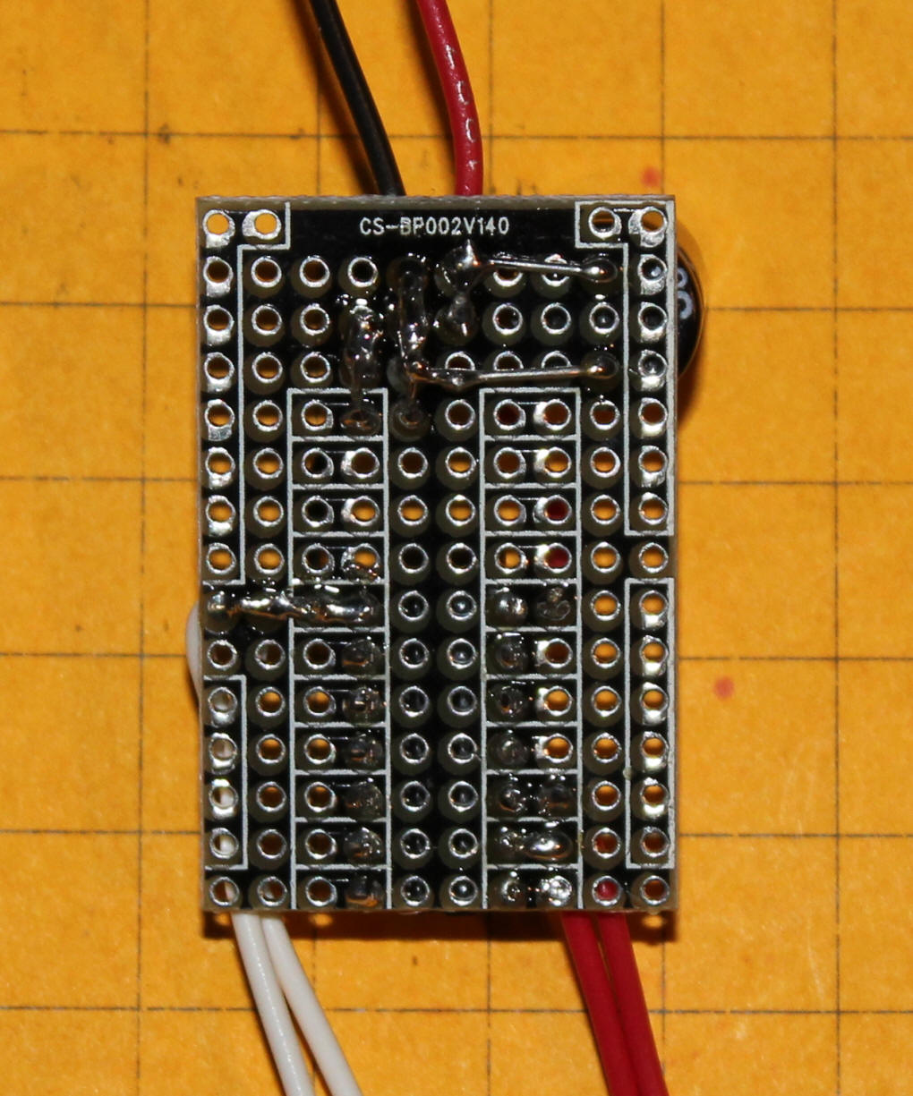
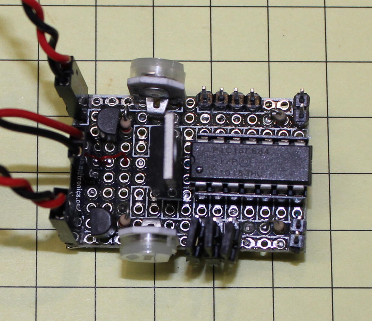
These photos show much more conventional wiring on a prototype board. The boards are available from www.sure-electronics.com and from their eBay store. Please note that the holes can be soldered on both sides and that groups of holes (surrounded by white boxes) are connected. If you want to disconnect any of these junctions you must cut through the board on both sides! This is the top view of the most basic circuit - the red & black wires at the top go to 5 volts DC, the two white wires go to the cathodes of the LEDs and the other two red wires go to the current limiting resistors that connect to the LED's anodes.
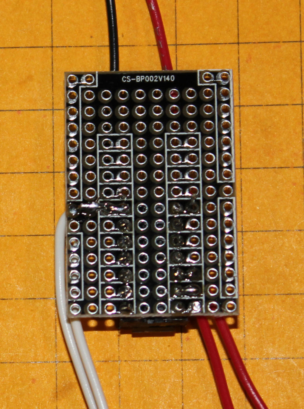
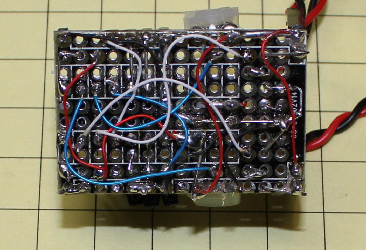
Here is the bottom of the same board.
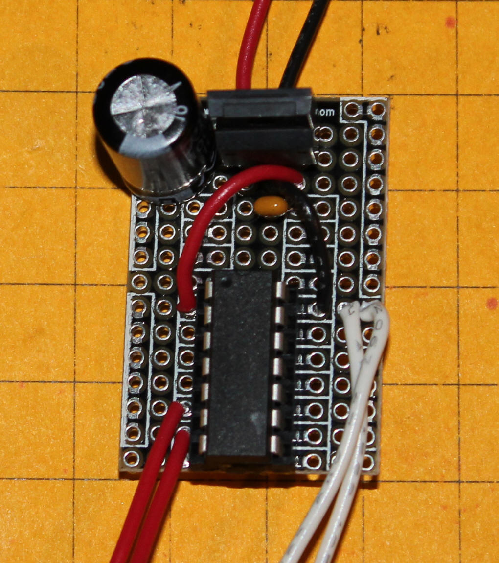
In this photo a 7805 voltage regulator and two filter capacitors have been added so that the circuit can operate from voltages ranging from 7 to 30 volts.
Here is the bottom view.
|
|||||||||||||||||||||||||||
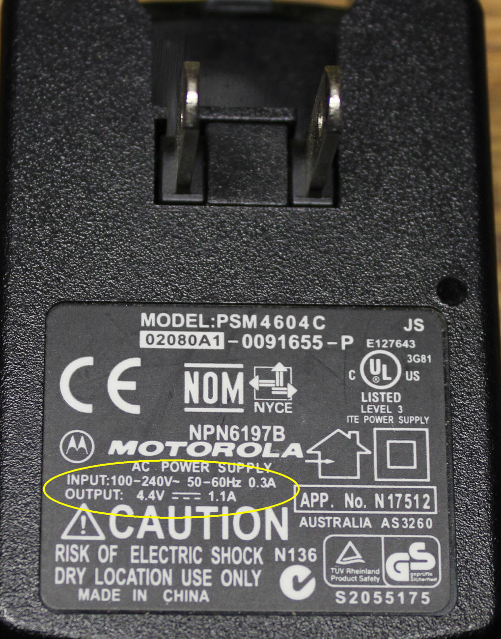
| Power Supply Tip If you would like to run the crossing controller from AC power without adding a voltage regulator the easiest route may be to use an old cellular phone charger. Many cell phone chargers supply between 4 and 5 volts. Just cut the cell phone plug off of the end, strip the exposed wires and test the voltage with a multi-meter. The red wire is usually (but not always!) positive and the black is negative. As long as it provides 5.5 volts or less it should work. This photo is of an old Motorola cell phone charger. As you can see from the label it puts out 4.4 volts DC at over 1 amp.
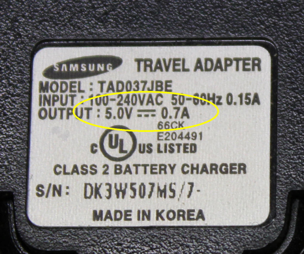
This Samsung charger puts out 5 volts at 0.7 amps. That is more than enough power for this project.
|
|||||||||||||||||||||||||||
| How it All Works The rest of this article details how the flasher chip can be wired to give a number of other modes. The wiring is similar to what was described above. The last part of the article shows a complete circuit board that can be used to simplify wiring and to give quick access to all of the flasher's modes. |
|||||||||||||||||||||||||||
| Using the Controller with more than 5 Volts If you want to run the controller from a plug-in power supply or other higher voltage source you will need to add a 5 volt voltage regulator to the circuit. Use of voltage regulators is discussed in great detail in this article: 5 Volt Power for Railway Electronics |
|||||||||||||||||||||||||||
| Schematic: Because a microcontroller is in charge of all timing and functions relatively few parts are needed. The schematic shows the most complex wiring that can be done with the chip including two transistors that are used to illuminate high power LEDs or incandescent bulbs.
The three switches, labeled SW1 through SW3, are used to configure the operation modes of the controller. The switches are actually pairs of pins that can either be jumpered (on) or not jumpered (off). Three switches can be set in eight different ways. They can be all off (000), one on and two and three off (001), one off, two on and three off (010) and so on. This table gives the options:
If this sequence looks vaguely familiar that is because it is the same as counting in binary or base 2. Notice that the counting starts at zero, not one, and ends at seven giving us eight options. The two potentiometers, R3 and R4, are used in some modes to adjust the flash rate and the time that the flashing will last. None, one or both of the potentiometers are used depending on the mode that is selected. The two trigger switches, SW4 and SW5, are used to start and stop the flashing depending on the mode that is selected. Transistors Q1 and Q2 are used to power light bulbs or LEDs that might draw more current than the 20 ma limit that the pins on the microcontroller will allow. If you plan on using small incandescent bulbs in the crossing signal you can supply up to 12 volts to them as shown in this modified segment of the schematic. The 2N2222 transistors can easily handle 100 ma or more when bulbs are flashing as they are not continuously on and the transistor has a chance to cool a bit between flashings. If more current is needed the 2N2222 transistors can be swapped out for N-Channel Mosfets or Darlingtons. Large transistors could easily be used to power extremely bright halogen bulbs.
During testing I used Lionel 12 volt red incandescent bulbs and they worked well. |
|||||||||||||||||||||||||||
| Modes The three jumpers, SW1, SW2 and SW3 are used to select modes. This table gives details on each mode.
When the unit is in modes 0-->4 the lights are full on or full off when flashing. When in modes 5-->7 one LED brightens gradually as the other dims. |
|||||||||||||||||||||||||||
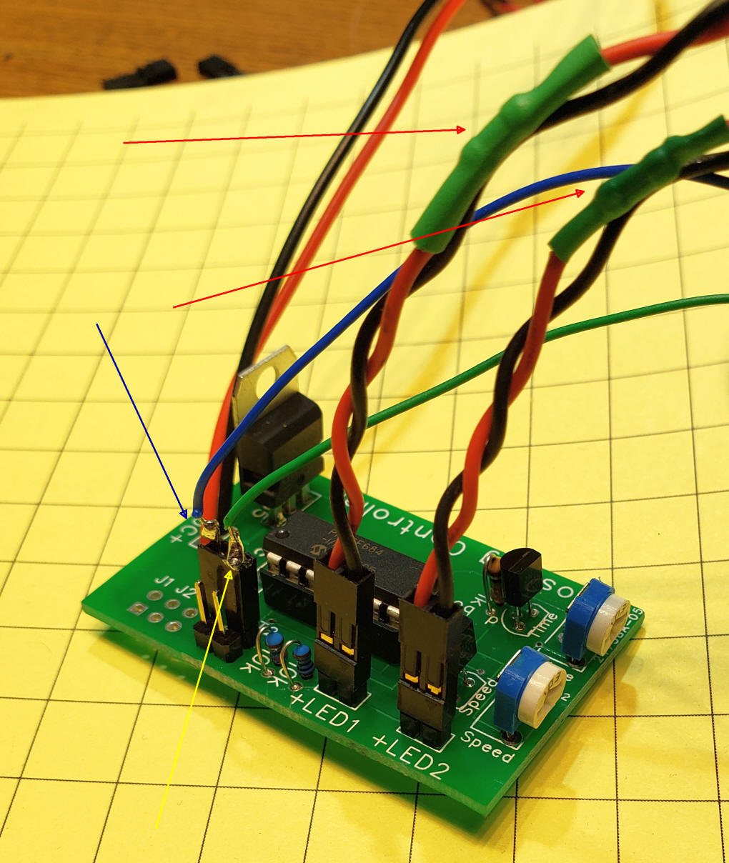
| Prototype The hand wired prototype is shown here. The microcontroller is the large chip to the right. The two pots are at top and bottom. The LEDs connect through the red/black wires at the upper left and lower left. Power is applied through the red/black wires at left center. The three jumper switches are at the lower center and the two triggers are at upper right and lower right. The large component in the center is a voltage regulator and the two 1/2 moon shaped components are the transistors that drive the LEDs or bulbs. The four pin header at the top is used to program the microcontroller.
Although the hand wiring on the bottom of the circuit board looks complicated it worked the first time I tried it!
|
|||||||||||||||||||||||||||
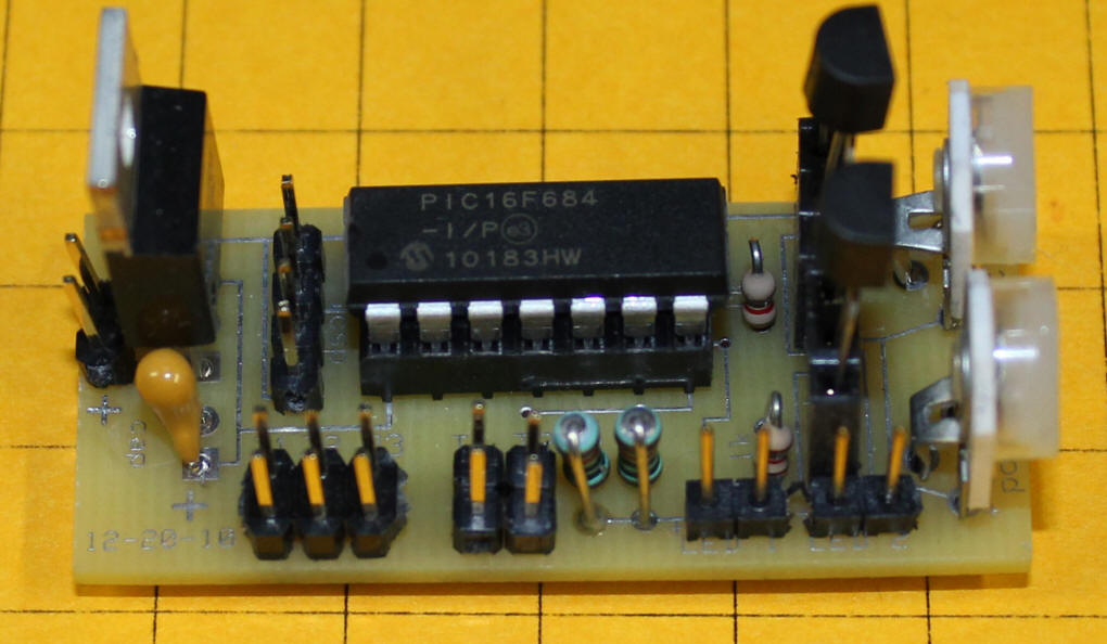
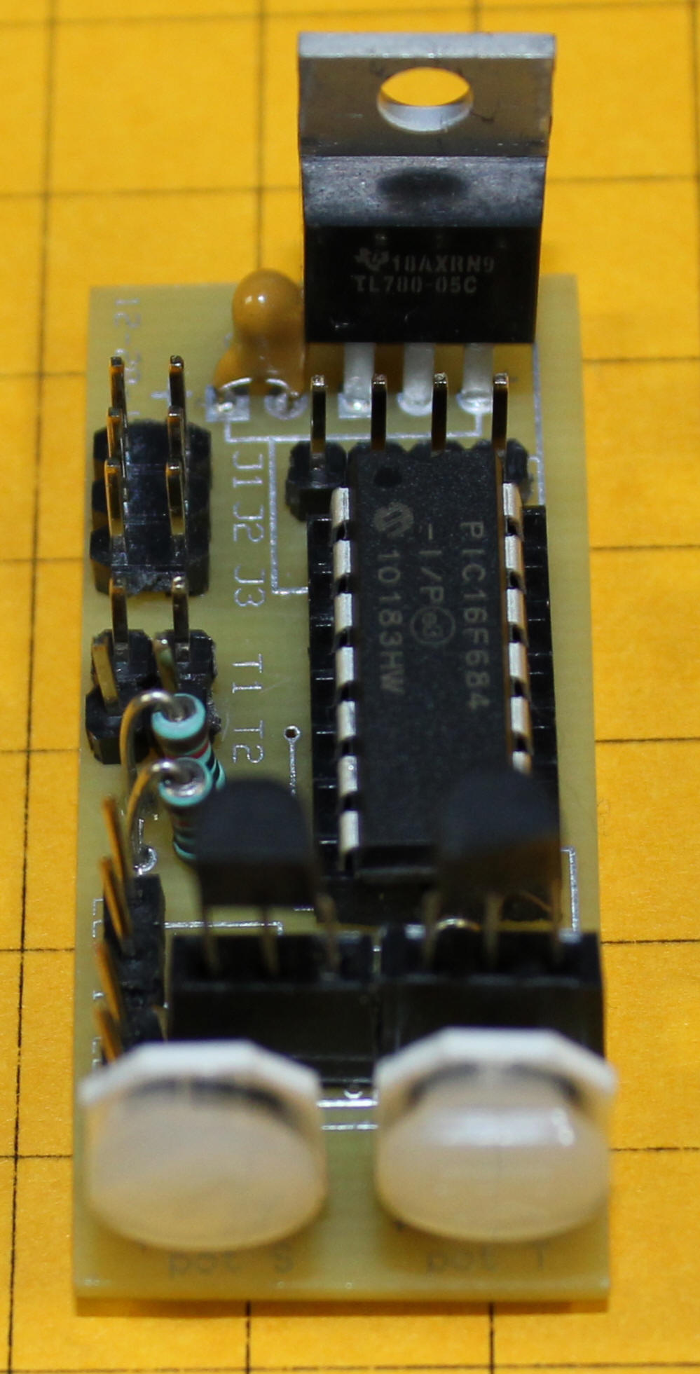
| Custom Circuit Board After successful testing of the prototype a custom board was designed and sent out for fabrication. The result is shown below. The two potentiometers are at the right edge and the two transistors are just behind them. On this board the transistors are mounted in sockets for testing. The three mode jumpers, composed of six pins, are in the lower left. The two pairs of pins to their right are the triggers. The LEDs connect to the pairs of pins in the lower right corner. Power goes to the two pins on the left edge.
In this photo you can clearly see the markings for jumpers J1, J2, J3 and the two triggers, T1 and T2.
|
|||||||||||||||||||||||||||
|
Mode Notes & Suggested Uses Modes 0, 1 and 2 are the most basic modes and work well with a simple crossing flasher that needs to be on most or all of the time. Modes 0 and 1 have the lights flashing alternately from the time the power is turned on till the power is turned off. Mode 2 is similar to mode 1 but Trigger 1 must be on for the lights to flash. Mode 3 is ideal for a crossing that you want to have activated only when a train is passing. Place a reed switch between the rails before the crossing and another reed switch after the crossing. These connect to Trigger 1 and Trigger 2. Attach a magnet to the bottom of the train. When the magnet goes over the first reed switch the crossing lights are turned on. They remain on until the other reed switch senses the magnet going over it. Note that the train can run in either direction as it does not matter which reed switch is hit first. Either will turn the crossing on and the other reed switch will turn it off. Mode 4 is similar to mode 3 but it only uses one trigger. When Trigger 1 is hit the crossing signal flashes for a time that is set by potentiometer #2. The time that the signal stays on can be varied from a few seconds to about 1 minute. Modes 5 through 7 were originally designed for use inside of a locomotive where the LEDs would be used as ditch lights. While this is a good use of the circuit I discovered that I really liked the way modes 5, 6 and 7 gradually brightened and dimmed the crossing signal bulbs. I think that many users might prefer these modes to the blink on/off modes in 0 through 4. Modes 5, 6 and 7 are similar in function to modes 2, 3 and 4. The main difference is that the LEDs are more gradually dimmed and brightened simulating ditch lights. If the circuit is used for ditch lights it would be logical to substitute white LEDs or incandescent lights for the red ones used for the crossing signal. In order to use the controller inside of a track powered locomotive you would need to add a few parts. A bridge rectifier would guarantee that polarity was never reversed and a voltage regulator and a capacitor or two would be needed. Such circuits are discussed in detail in two articles: |
|||||||||||||||||||||||||||
| Conclusion I think that you will agree that using a microcontroller to control a crossing signal can give a wide array of options. The eight shown here are only the beginning as other modes, like using LEDs to simulate flashing strobe lights or a welder or flashing out a message in Morse Code, are only a matter of changing the software. Please let me know what ideas you have and if I can help you to implement them. If you would like to experiment with the flashing chip please contact me directly at dave@davebodnar.com. The chips are $4.00 each plus $2.00 shipping for any number up to 10. I can also put together a complete kit of parts. Pricing for that is on the Pricing page. |
|||||||||||||||||||||||||||
|
<Right click on the box below and select Play>
Custom Ditch Light Modification #1 This video shows a software modification that enhances the unit's ability to simulate ditch lights.
|